
SA5 - Surveillance Camera FRIEDLAND - Free user manual and instructions
Find the device manual for free SA5 FRIEDLAND in PDF.


| Product Type | Indoor/Outdoor Surveillance Camera |
| Model | SA5 |
| Brand | Friedland |
| Dimensions (approx.) | 120 mm x 70 mm x 70 mm |
| Weight (approx.) | 200 g |
| Power Supply | DC 12V, 1A (adapter included) |
| Power Consumption | 5 W (typical) |
| Video Resolution | 1080p Full HD (1920x1080) |
| Field of View | 120° diagonal |
| Night Vision | IR LEDs up to 10 meters |
| Motion Detection | Yes, with adjustable sensitivity |
| Two-Way Audio | Built-in microphone and speaker |
| Storage | MicroSD card up to 128 GB (not included) |
| Connectivity | Wi-Fi 802.11 b/g/n, 2.4 GHz |
| App Support | Compatible with iOS and Android |
| Weatherproof Rating | IP65 (suitable for outdoor use) |
| Operating Temperature | -20°C to 50°C |
| Maintenance | Clean lens with soft dry cloth; check connections periodically |
| Safety | Use only supplied adapter; do not expose to extreme heat |
| Spare Parts & Repairability | Replacement power adapter and mounting kit available; contact support for repairs |
Frequently Asked Questions - SA5 FRIEDLAND
User questions about SA5 FRIEDLAND
0 question about this device. Answer the ones you know or ask your own.
Ask a new question about this device
Download the instructions for your Surveillance Camera in PDF format for free! Find your manual SA5 - FRIEDLAND and take your electronic device back in hand. On this page are published all the documents necessary for the use of your device. SA5 by FRIEDLAND.
USER MANUAL SA5 FRIEDLAND
6 Zone Communicating Wirefree Alarm System

Installation & Operating Manual
FOREWORD
All components in this wirefree Alarm System are designed and manufactured to provide a high standard of security protection and long, reliable service.
The system is designed for ease of installation using only conventional domestic tools. However, it is essential that the installer reads and fully understands the advice and procedures contained in this manual and plans the system before proceeding with the installation.
During installation, it is important that the procedures described in this manual are followed in sequence.
This manual should be retained in a safe place for future reference.
No radio operating licence is required for this equipment.
IMPORTANT
All components, with the exception of the External Solar Siren are suitable for mounting in dry interior locations only.
DECLARATION
Novar ED&S hereby declares that this wirefree alarm system is in compliance with the essential requirements and other relevant provisions of the Radio and Telecommunications Terminal Equipment (R&TTE) directive, 1999/5/EC.
Tools and Equipment Required:
No.0, No.1 and No.2 Philips Screwdrivers
5 & 6mm Masonry Drill Bits
Drill, Bradawl, Small Spirit Level
SAFETY
Always follow the manufacturers advice when using power tools; steps, ladders etc. and wear suitable protective equipment (e.g. safety goggles) when drilling holes etc.
Before drilling holes in walls, check for hidden electricity cables and water pipes, the use of a cable/pipe locator maybe advisable if in doubt.
When using ladders, ensure that they are positioned on a firm stable surface at the correct angle and suitably secured before use.
The use of ear defenders is advisable when working in close proximity to the Siren due to the high sound level produced by this device.
DEVICE RANGE
The quoted range of the system devices (see component specification on rear cover) is measured in ideal conditions. Any solid object (e.g. walls, ceilings, reinforced PVC doors etc) placed between the transmitter and Receiver device will reduce the transmission range of the devices.
The amount by which the range will be reduced is dependant upon the nature of the barrier. e.g.
Wall Type Range Reduction
Dry-lined partition wall: 10-30%
Single layer brick wall: 20-40%
Double layer brick wall: 30-70%
Metal Panel/Radiator: 90-100%
Note: The effect on the range of multiple walls is cumulative. i.e. if there are two brick walls in the way, the range will be reduced by up to 40% by each wall.
SYSTEM SECURITY
This system has been designed to both detect intruders and act as a strong deterrent to would-be intruders when installed correctly.
Please remember that given adequate knowledge and time it is possible to overcome any alarm system and we therefore recommend that an Intruder Alarm is used in conjunction with good physical protection such as security window and door locks.
All units in the system are encoded to operate together using an 8 bit House Code which is configured by the user/installer to provide the identification code for your installation. The system House Code can be changed at any time by the user.
The system is operated from one or more Remote Control units and/or the Control Panel. Care should be taken to ensure that your Remote Control Unit(s) are not lost or the User Access Codes for the Control Panel do not become known to other people as this will compromise the security of your system. In either event the system house code and User Access Codes should be changed as soon as possible.
IMPORTANT: All units in your system must be set to the same House Code which must be changed from the factory supplied setting.
CONTENTS
Page No.
Page No.
KIT CONTENTS 2
INTRODUCTION AND OVERVIEW 3
Multiple Users 3
System Arming 3
Entry/Exit Delay 3
Zones 3
Zone Lockout 4
Quick Set 4
Final Exit Set Zone 4
Walk Through Zone 4
Omit Zone 4
Event Log 4
Chime 4
Voice Dialler 4
Remote Manager 4
Latch-Key 5
Answer-Phone 5
Voice Memo 5
Remote System Control 5
Tamper Protection 5
Jamming Detection 5
Battery Monitoring 5
System House Code 6
PLANNING AND EXTENDING YOUR
WREFREE ALARM SYSTEM 7
REMOTE CONTROL UNIT 8
General Information 8
Configuring the Remote Control 9
CONTROL PANEL 9
Positioning the Control Panel 9
Installing the Control Panel 10
Configuring the Control Panel House Code 11
Testing the Control Panel & Remote Control 11
PASSIVE INFRA RED (PIR)
MOVEMENT DETECTORS 12
Positioning the PIR Movement Detectors 12
Installing and Configuring the PIR
Movement Detectors 13
Testing the PIR Movement Detectors 14
MAGNETIC CONTACT DETECTORS 14
Positioning the Magnetic Contact Detectors 15
Installing and Configuring the Magnetic
Contact Detector 15
Testing the Magnetic Contact Detector 16
Power-up of the Solar Siren 19
Testing the Solar Siren 19
EXTERNAL CONNECTIONS 19
Testing an Installed System 20
DEFAULT SETTINGS 22
Reset Factory Default Conditions 22
PROGRAMMING 23
User Setup 24
System Setup 25
Zone Setup 28
Voice Dialler Setup 30
Full Arm Setup 32
Part-Arm 1 Setup 33
Part-Arm 2 Setup 34
Time & Date Setup 35
Latch Key Setup 35
Answer Phone Setup 36
Remote manager Setup 37
OPERATING INSTRUCTIONS 38
Arming The System 38
Part-Arming The System: Part-Arm 1 38
Part-Arming The System: Part-Arm 2 38
Disarming the System 39
Quick Set 39
Omit Zone 39
Personal Attack (PA) Alarm 39
Tamper 39
Chime 39
Event-Log 40
Leaving a Voice Memo Message 40
Replaying and Deleting Messages at the
Control Panel 40
Remote Phone Access and Control 40
Siren Service Mode 41
Siren Operating Mode 42
Battery Monitoring 42
MAINTENANCE 43
ALARM RECORD 44
TROUBLE SHOOTING 45
EXTENDING YOUR ALARM SYSTEM 48
COMPONENT SPECIFICATION Back Cover
KIT CONTENTS
The Alarm System should contain the following components.
1 x External Solar Siren
1 x Control Panel
1 x Remote Control
2 x PIR Movement Detectors
2 x Magnetic Contact Detectors
Also included:
Telephone Connection Lead
Power Supply Adaptor
Installation & Operating Manual
Fixing pack
Batteries

6V/1.2Ahr Sealed lead acid battery
(supplied fitted in Solar Siren and Control Panel)
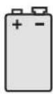
9V PP3 Alkaline battery
(for PIR Detectors)

3V CR2032
Lithium Coin Cell
(for Remote Control and Magnetic Contact Detectors)
EXTENDING THE ALARM SYSTEM
The following additional accessories are available to enhance your system and provide further protection and a higher level of security where required.
Component: Product Code
Two Magnetic Contact Detectors and one Remote Control SU1
Two Passive Infra-Red
Movement Detectors SU2
Two Remote Controls SU3
Two Magnetic Contact Detectors SU4
Remote Keypad SU5
External Solar Siren SU6
Full details of these accessories are given on page 48.

External Solar Siren

Control Panel

natural_image
Line drawing of a rectangular device with a curved top and internal grid pattern (no text or symbols)PIR Movement Detector

natural_image
Simple line drawing of a test tube with a vertical panel and internal components (no text or symbols)Magnetic Contact Detector

Remote Control
INTRODUCTION AND OVERVIEW
MULTIPLE USERS
The system allows for up to 6 Users and a Master User to be configured. This allows the system Event Log to maintain a record of which users have armed and disarmed the system. Each user will have a different Access Code. In addition a 4 second voice recorder facility enables the users name to be recorded for use with the Latch-Key facility.
Only the Master User has access to the programming functions and is able to configure the system.
Note: Any Remote Control Units on the system will be recorded as User 6.
SYSTEM ARMING
The system has a full ‘Arm’ and two ‘Part-Arm’ modes. ARM will ‘Arm’ all zones while the ‘Part-Arm’ modes will only arm the zones that are enabled for the particular part-arm mode.

natural_image
Architectural line drawing of a two-story house with windows and a smaller structure (no text or symbols)Full Arm
For example:
The system could be configured such that during night time, ‘Part-Arm 1’ would arm only zones protecting the lower floor and outbuildings leaving the upper floor free for movement without triggering the alarm.

natural_image
Simple line drawing of a two-story house with three smaller houses beside it (no text or symbols)Part-Arm 1

natural_image
Simple line drawing of a two-story house with three smaller structures beside it (no text or symbols)Part-Arm 2
During the day while the property is occupied ‘Part-Arm 2’ would arm only the zones protecting the outbuildings. However, when the property is left unoccupied, the full ‘Arm’ mode will arm all zones to protect the entire property, (i.e. upper and lower floors and outbuildings).
ENTRY/EXIT DELAY
When the system is armed with the Exit-Delay enabled, no alarm signal from any detector on an active zone will be able to initiate an alarm until the Exit-Delay has expired. This enables the system to be armed from within the property and allows time for the user to exit the property without triggering an alarm. If the Exit-Delay is disabled then detectors on active zones will immediately be able to initiate an alarm as soon as the system begins to arm.
The system Exit-Delay may be configured for between 10 to 250 seconds or disabled completely.
If a detector on a zone with its Entry-Delay enabled is triggered, then an alarm condition will not occur until the Entry-Delay period has expired. This allows time for the user to re-enter the property and disarm the system before an alarm condition occurs. Generally only the zones on the main entry route to the property will be configured with an Entry-Delay. The remaining zones would be configured with their Entry-Delay disabled allowing them to immediately initiate an alarm the instant a detector on the zone is triggered.
The Entry-Delay for each zone may be configured for between 10 to 250 seconds or disabled completely.
Note: To conserve power and maximise battery life the PIR Detector will only detect movement if there has been no movement detected within the previous 2 minutes. Consequently the PIR Detector will not become active until the protected area has been free from movement for more than 2 minutes.
ZONES
The system incorporates 6 wirefree Alarm Zones for the connection of the system detectors that are used to independently monitor different areas of the property. In addition to standard intruder protection, each zone may also be configured to operate in one of four other modes:
- 'PANIC/PA' mode provides 24 hour monitoring of any Personal Attack (PA) switches incorporated into the system.
- '24-hour Intruder' mode provides 24 hour intruder protection for areas/zones where continuous monitoring is required, (e.g. gun lockers).
- 'Fire' mode provides 24 hour monitoring of any Fire/Smoke detectors incorporated into the system.
- 'Test' mode allows a zone to be monitored while the system is armed. If a detector on a test zone is triggered an entry will be recorded in the Event Log but an alarm will not occur.
In addition there is the facility to connect 4 hard wired zones to the Control Panel, each of which is
fully configurable with the same features as the wirefree zones.
ZONE LOCKOUT
If a detector on an active zone is triggered while the system is armed an alarm condition will occur. After the programmed alarm duration has expired the alarm will stop and the system will automatically reset. Subsequent detectors triggered will again initiate an alarm condition. If a single zone initiates an alarm condition more than three times then that zone will be 'Locked Out' and any further alarm signals from that zone will be ignored until the system is disarmed.
Note: The 'Zone Lockout' feature can be disabled if required.
QUICK SET
The system may be fully armed in 5 seconds using the quick set facility, overriding the programmed exit-delay. This is useful for setting the system at night when the exit-delay warning beep will be silenced after just a few seconds.
FINAL EXIT SET ZONE
Triggering a detector on a Final Exit zone during the exit-delay will cause the delay to reset to 5 seconds with the system arming 5 seconds later.
WALK THROUGH ZONE
This feature may be used to temporarily disable detectors on zones covering the route between the main entry door and the Control Panel.
If the system is armed and the property is accessed via the "Entry-Door" zone then the setup entry-delay will operate as normal. However all "Entry-Route" zones will be disabled to allow free access to the Control Panel to Disarm the system before the entry-delay on the "Entry-Door" zone expires an alarm occurs.
If the first zone triggered is the "entry-route" zone then the system will operate according to the zones normal configuration.
Notes: The zone configured as the "Entry Door" must be setup with an Entry-Delay sufficient to reach the Control Panel and Disarm the system.
Zones configured as the "Entry Route" should be setup without an Entry-Delay.
OMIT ZONE
A zone may be temporarily omitted when the system is armed using the Omit feature. When the system is next disarmed any zones set to Omit will be cancelled.
EVENT LOG
The Control Panel incorporates a memory capable of storing the last 50 system events. This enables the user to see which user has Armed/Disarmed the system and if and when any alarms occurred. The time, date and details of the event type will be recorded for each system event.
CHIME
Chime is a low security facility for use when the system is Standby mode. If the Chime feature is ON, and a detector on a zone that has its Chime function enabled is triggered, the internal sounder will produce a low volume warning tone. A typical use of the Chime function would be to warn that a door or particular area has been accessed.
VOICE DIALLER
This system incorporates a telephone voice dialler that is used to call for help and/or notify the user that the system has been triggered and an alarm has occurred.
If the Voice Dialer is enabled and an alarm condition occurs, the system will call for help using your recorded alarm message and up to four telephone numbers. When the telephone voice dialer is activated it will call the first enabled number in the dialling sequence and replay the recorded alarm messages for the configured 'Play Time'. The recipient must acknowledge the message by pressing the * button on their telephone keypad. If the call is unanswered or an acknowledgment signal is not received then the next active number in the dialling sequence will be called. The dialler will continue calling each number in turn until either all numbers in the sequence have been dialled the set number of times or the dialling sequence is cancelled by an acknowledged signal from the recipient.
REMOTE MANAGER
As an alternative to the Voice Dialer the system may be configured to interface direct with an Alarm Monitoring Service using the Ademco Contact ID communications protocol.
This is an independent service not provided by Friedland, (see enclosed leaflet for details).
LATCH KEY
When the system is disarmed the Latch-Key facility, if enabled, will call the first latchkey phone number and replay the user message (recorded under user setup) for the set 'Play Time'. The recipient must acknowledge the message by pressing the * button on their telephone keypad. If the call is unanswered or an acknowledgment is not received then the second latchkey phone number will be called. The voice dialer will continue calling each number in turn until each number has been dialed the set number of times or the sequence is cancelled/acknowledged by the recipient.
For example, the latchkey facility is useful to inform parents that a child has returned from school and disarmed the system.
ANSWER PHONE
The Control Panel includes an answer-phone facility. The answer phone will record and store a maximum of 6 messages with each message being limited to a 30s duration.
Messages may be retrieved either direct from the Control Panel or by dialing into the system from a phone.
VOICE MEMO
In addition it is also possible to record messages at the Control Panel using the 'Voice-Memo' facility. Each voice-memo message is limited to a maximum duration of 30s and counts as an answer phone message.
REMOTE PHONE ACCESS AND CONTROL
It is possible to dial into the system via the connected telephone line to interrogate the system status and to have basic control over the system, (e.g. to Arm and Disarm the system). You may also activate the microphone on the control panel to Listen-In to what is happening in the protected property.
Answer phone and Voice-memo messages may also be accessed remotely.
TAMPER PROTECTION
All system devices (except any Remote Control Units) incorporate Tamper protection features to protect against unauthorised attempts to interfere with the device.
Any attempt to remove the battery cover from any device (except a Remote Control) or to remove the Solar Siren or Control Panel from the wall will initiate an alarm condition (unless the system is in Test or Programming modes), even if the system is Disarmed.
JAMMING DETECTION
In order to detect any attempts to illegally jam the radio channel used by your alarm system, a special jamming detection function is incorporated into the Control Panel and Solar Siren. If this feature is enabled, and the radio channel is jammed continuously for 30 seconds, when the system is armed, the Solar Siren will emit a pre-alarm series of rapid bleeps for 5 seconds. If the jamming continues for a further 10 seconds or more a full alarm condition will occur. In addition if the system is jammed for more than three periods of 10 seconds in a 5 minute interval, this will also generate a Full Alarm condition. The jamming detection features in the Control Panel and Solar Siren operate independently.
The Jamming Detection circuit is designed to permanently scan for jamming signals. However, it is possible that it may detect other local radio interference operating legally or illegally on the same frequency. If it is planned to operate the jamming detection feature we recommend that the system is monitored for false jamming alarms for at least 2 weeks prior to leaving the Jamming Detection function permanently enabled.
Note: The jamming detection features incorporated into the Control Panel and optional Solar Siren operate independently.
BATTERY MONITORING
All devices powered by non-rechargeable batteries incorporate a battery level monitoring feature which will warn of a low battery status. In addition the Control Panel will also indicate a low battery status within any Passive Infra-Red or Magnetic Contact Detector on the system. The batteries on any device indicating a low battery status should be replaced immediately.
SYSTEM HOUSE CODE
In order to prevent any unauthorised attempt to operate or disarm your system, you must configure your system to accept radio signals only from your own system devices. This is done by setting a series of eight miniature (DIP) switches in all devices (except the Control Panel) to the same ON/OFF combination (the House Code) selected by the user/installer. The Control Panel is then programmed to operate only with devices set to this House Code. All detectors and Remote Control Unit(s) must be configured with the same House Code in order for the system to operate correctly.
Inside the Siren, Detectors and Remote Control Unit is a series of 8 DIP switches.
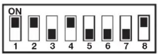
$$ \text { e.g. } \quad = \begin{array}{l} \text { Switch 1 } \ \text { set to ON } \ \text { position } \end{array} $$
The House Code is set up by moving each of the 8 switches in each device to the same randomly selected ON/OFF sequence. When setting the DIP switches, ensure that each switch 'clicks' fully into position. Use the tip of a ballpoint pen or a small screwdriver to move each switch in turn.
Note: It is recommended that the system House Code is always changed to a code other than the factory setting.
PLANNING AND EXTENDING YOUR WIREFREE ALARM SYSTEM
Before attempting to install your Alarm System it is important to study your security requirements and plan your installation.
PIR Movement Detectors are used to protect the main areas of the property, (e.g. lounge, study, hallway and landing, etc). Magnetic Contact Detectors are used to protect the main access points to the property, (e.g. front door, back door, patio doors etc). However, they can also be used to protect other vulnerable doors/windows or access doors to important rooms.
TYPICAL INSTALLATION
The following example below shows typical property incorporating the suggested positions for the External Siren, PIR and Magnetic Detectors. Use this as a guide for your installation in conjunction with the detailed positioning requirements for each device provided in the appropriate installation sections in this manual for planning your intruder alarm system.

flowchart
graph TD
    A["External Solar Siren"] --> B["PIR Movement Detector"]
    C["Magnetic Contact Detector"] --> D["Shed"]
    E["LED Control Panel"] --> F["KITCHEN"]
    F --> G["Ground Floor"]
    H["PO Box"] --> I["PO Box"]
    J["Car with Remote Control"] --> K["Car with Remote Control"]
    L["PO Box"] --> M["PO Box"]
    N["PO Box"] --> O["PO Box"]
    P["PO Box"] --> Q["PO Box"]
    R["PO Box"] --> S["PO Box"]
    T["PO Box"] --> U["PO Box"]
    V["PO Box"] --> W["PO Box"]
    X["PO Box"] --> Y["PO Box"]
    Z["PO Box"] --> AA["PO Box"]
    AB["PO Box"] --> AC["PO Box"]
    AD["PO Box"] --> AE["PO Box"]
    AF["PO Box"] --> AG["PO Box"]
    AH["PO Box"] --> AI["PO Box"]
    AJ["PO Box"] --> AK["PO Box"]
    AL["PO Box"] --> AM["PO Box"]
    AN["PO Box"] --> AO["PO Box"]
    AP["PO Box"] --> AQ["PO Box"]
    AR["PO Box"] --> AS["PO Box"]
    AT["PO Box"] --> AU["PO Box"]
    AV["PO Box"] --> AW["PO Box"]
Typical Installation using only detectors supplied:
- Place the 1st Magnetic Contact detector (set on Zone 1) on the front door
- Place the 1st PIR Detector (also set on Zone 1) in the hall covering the Control Panel and routes between downstairs rooms.
-
Place the 2nd Magnetic Contact detector (set on Zone 2) on the back or Patio doors.
-
Place the 2nd PIR Detector either
i) downstairs in the main living room containing most valuables, (set on Zone 3), or
ii) upstairs on the landing covering the access routes between bedrooms and the stairs, (set on Zone 5). This will be inactive if Part-Arm 1 is used.
The system may be expanded with additional Detectors, Remote Controls and Keypads to provide even greater protection. However the following rules should be followed:
a) Any detectors covering the main door and the route to the Control Panel should be set on zone 1 only.
b) Any detectors covering other areas of the ground floor should be set on zones 2 to 4 only.
c) Any detectors placed upstairs (which are not required when activating Part-Arm) should be set on zones 5 or 6 only.
Note: All system components must be configured with the same House Code.
The system default settings are pre configured to provide a basic functional system to suit most typical basic installations:
- Detectors on Zone 1 will have a 30s entry delay period. Detectors on all other zones are configured as INSTANT, (i.e. they have no entry delay).
• The system has a 3 minute alarm duration. - The zone Lockout feature is ON so that if any single zone triggers an alarm more than three times they will be ignored until the system is next disarmed,
(this feature helps protect against continuous false alarms).
- PART-ARM 1 is configured with a 30s exit delay and operates with detectors on zones 1 to 4 only.
• PART-ARM 2 is OFF. - All other system features, (e.g. telephone dialler, answer phone, Latch-Key, Chime etc) are OFF or not programmed.
Important:
All system components must be configured with the same House Code.
As soon as installation is complete
- The default Master User Access Code for the Control Panel should be changed to your own code that only you know.
- User Access Codes 1-6 for the Control Panel should be changed to your own codes that only the relevant system user knows.
- The system Time and Date must be configured.
Note: If you wish to change the system configuration away from the above example and system default settings and customise it to your own unique requirements and activate any of the more advanced system features then refer to the Programming section on page 23.
REMOTE CONTROL UNIT
The Remote Control Unit(s) are used to Arm, Part-Arm and Disarm the system.

The Remote Control Unit also incorporates a Personal Attack (PA) switch. Activating the PA switch on the side
of the Remote Control will immediately initiate a Full Alarm condition whether the system is Armed or Disarmed. The alarm can be cancelled by pressing the 'DISARM' button on the Remote Control or via the Control Panel.
Any number of Remote Control Units can be used with your system, providing they are all coded with the system House Code.
The Remote Control is powered by a CR2032 type Lithium cell which under normal conditions will have an expected life in excess of 1 year. Under normal battery conditions the LED on the Remote Control will only illuminate when a button is pressed. However, under low-battery conditions this LED will continue to flash after the button has been released. When this occurs the battery should be replaced as soon as possible.
CONFIGURING THE REMOTE CONTROL
- Remove the rear cover by undoing the small screw on the rear of the Remote Control.
- Select and record a random combination of 'ON' and 'OFF' positions for the DIP switches. This will be the system House Code that enables all elements of your transmitters to communicate with the Control Panel.
IMPORTANT: The House Code for your system should be changed from the factory default setting
-
Ensure that the jumper link located immediately below the House Code DIP switches is fitted in position for use with this alarm system.
-
Insert the battery under the clip ensuring that the +ve terminal faces upwards away from the PCB.

- Replace the rear cover and fixing screw. Do not over tighten the screw as this could damage the thread.
CONTROL PANEL

Outside View of Control Panel
POSITIONING THE CONTROL PANEL
When choosing a suitable location for the Control Panel, the following points should be considered.
- The Control Panel should be located in a position out of sight of potential intruders and in a safe location, but easily accessible for system operation.
- The Control Panel should be mounted on a sound flat surface to ensure that the rear tamper switch on the Control Panel is closed when the Panel is mounted. The Control Panel should be mounted at a convenient height of between 1.5 and 2m and in a position where it will be seen each day.
Note: If small children are in the household, a further consideration should be given to keeping the units out of their reach.
-
It is recommended that the Control Panel should be positioned such that the Exit/Entry tone (emitted by the Control Panel) can be heard from outside the property.
-
The Control Panel should be mounted within a protected area so that any intruder cannot reach the Control Panel without opening a protected door or passing through an area protected by a PIR movement detector when the system is armed.
-
The Control Panel must be located within reach of a mains socket.
-
If the telephone based functionality is to be used then the Control Panel will need connecting to a convenient telephone point.
Note: It is recommended that the telephone connection lead is not extended beyond 5m
before connecting to a telephone master or secondary outlet.
- Do not locate the Control Unit closer than 1m to any large metallic object, (e.g. mirrors, radiators, etc) as this may affect the radio range of the Control Panel.
INSTALLING THE CONTROL PANEL
- Undo the two captive fixing screws on top of the panel and open the cover. The cover is hinged along the bottom edge.
- Unclip and remove the two back-up batteries on either side of the panel.
- Hold the Control Panel in position on the wall and mark the positions of the four fixing holes. Remove the Panel and drill four 5mm holes and fit the 25mm Wall Plugs.
Note: The wall plugs supplied with the product are not suitable for plasterboard walls, if mounting the Control Panel onto plasterboard use appropriate wall plugs.
IMPORTANT: Do not drill the fixing holes with the Control Panel in position; as the resulting dust and vibration may damage the Control Panel's internal components and invalidate the guarantee.
- Fit two 18mm No.4 screws into the top holes until almost fully home and hang the Control panel over these screws using the two keyhole slots in the top corners of the panel casing.
- Route the cable from the Power Supply Unit up behind and on the right hand side of the Control Panel and connect the plug to the DC power socket in the panel. Ensuring that the cable is not trapped between the panel and the wall.
- Fix the Panel to the wall using two 18mm No.4 screws in the lower two fixing holes in the panel and tighten the upper fixing screws until they just grip the casing. Do not over tighten the fixing screws as this could damage or distort the casing.
- Ensure that the "Reset" and the "Hard-Wired Siren tamper detect" jumper links are set in the OFF position.
- Connect battery leads to both back-up batteries and refit batteries.
Battery 1 (left): Red lead to +ve battery terminal
Blue lead to -ve battery terminal
Battery 2 (right): Blue lead to +ve battery terminal
Black lead to -ve battery terminal

IMPORTANT: Take care when connecting battery leads to the batteries as connecting incorrectly could damage the batteries or the Control Panel.
Note: The Power LED may flash to indicate that the unit is being operated from the back-up batteries and that mains supply is not present.
- If fitted, remove the plastic film covering the LCD display and on the display window on the cover.
- Close the lid of the Control Panel and tighten the captive fixing screws.
- Plug in and switch ON the Power Supply Unit, (the Power LED should illuminate).
- If required, connect the Control Panel to the telephone line using the cable supplied by inserting small RJ11 plug into socket marked LINE located on the bottom edge of the Control Panel.
If the cable supplied is not long enough to reach a suitable phone point then it will need extending using a coupler and extension lead (not supplied).
Note: If the Panel Tamper alarm sounds during the installation reset the alarm by pressing:

User Access Code
on the Control Panel Keypad.
CONFIGURING THE CONTROL PANEL HOUSE CODE
With unit in Standby mode (Power LED only illuminated).
- Press

Master User Access Code
'1. USER SETUP' will be displayed.
This puts the Control Panel into programming mode.
- Use the ↑ and ↓ buttons to scroll through the menu until '2. SYSTEM SETUP' is displayed and press ENTER .
'2. SYSTEM SETUP' is displayed.
- Press

The current House code setting will be displayed. 4. The new system House Code can be programmed either directly at the Control Panel or via a Remote Control Unit.
At the Control Panel:
Press buttons 1-8 on the Control Panel to configure the display so that the required house code is displayed on the screen. As each button is pressed the corresponding digit in the house code will change to the opposite state, ("0" or "1").
$$ \begin{array}{l} 1 = \text { House Code DIP Switch On / Up } \ 0 = \text { House Code DIP Switch Off / Down } \ \end{array} $$
Using a Remote Control:
With the required House Code already configured on the Remote Control, press 🔍.
The Control Panel will beep twice to acknowledge the signal. The display will change to show the received house code on lower line of the display beneath the corresponding DIP switch numbers (1-8).
- Press ENTER to save the new setting.
- Press ESC ESC to return to Standby mode.
TESTING THE CONTROL PANEL & REMOTE CONTROL
- Press

User Access Code
to put the system into Test mode.
'TEST MODE – WALK TEST' will be displayed.
- Press to activate Walk Test.
'Walk Test Waiting...' will be displayed.
- Press the buttons on the Remote Control in turn, as each button is pressed the Control Panel will beep and display the function of the button being pressed on the screen.
- Test the range of the Remote Control by pressing the 'DISARM' button on the Remote Control from in and around the property and from all locations where you plan to install detectors. Check that the Control Panel acknowledges the signal from the Remote Control each time the 'DISARM' button is pressed.
- Press ESC to return to the top level menu of TEST MODE.
PASSIVE INFRA RED (PIR) MOVEMENT DETECTORS
PIR detectors are designed to detect movement in a protected area by detecting changes in infra-red radiation levels caused for example when a person moves within or across the devices field of vision. If movement is detected an alarm signal will be generated, (if the system is armed). PIR detectors will also detect animals, so ensure that pets are not permitted access to areas fitted with Passive Infra Red Movement Detectors when the system is armed.
The Detector incorporates a tamper protection feature to protect against attempts to interfere with the device. If the battery cover is removed, an alarm will immediately occur at any time.
The Detector also incorporates a sensitivity adjustment feature to compensate for situations where the detector may be affected by environmental changes, (e.g. insects, air temperature, etc).
To conserve power and maximise battery life the PIR detector will only detect movement if there has been no movement detected within the previous 2 minutes.
The PIR Detector is powered by a PP3 Alkaline battery which under normal conditions will have an expected life in excess of 1 year. When the battery level drops, with the PIR in normal operation mode and the battery cover fitted, the LED behind the detection window will flash. When this occurs the battery should be replaced as soon as possible. (Note: in normal operation with the LED behind the lens will not flash on detection of movement).
Any number of PIR Movement Detectors can be used with your system, providing they are all coded with the system House Code and are mounted within effective radio range of the Solar Siren.
POSITIONING THE PIR MOVEMENT DETECTORS
The recommended position for a PIR Movement Detector is in the corner of a room mounted at a height between 2 and 2.5m. At this height, the detector will have a maximum range of up to 12m with a field of view of 110°.
The Position of the PCB inside the PIR can be set to 5 different positions to adjust the range of the detection pattern created by the PIR. Setting the PCB in position 3 will reduce the range to approximately 9m, with position 1 providing a range of approximately 6m. The recommended position setting for the PCB is in position 5.


Detection Zone Pattern for PCB in position 5
When considering and deciding upon the mounting position for the detector the following points should be considered to ensure trouble free operation:
- Do not position the detector facing a window or where it is exposed to or facing direct sunlight. PIR Movement Detectors are not suitable for use in conservatories.
- Do not position the detector where it is exposed to draughts.
- Do not position the detector directly above a heat source, (e.g. fire, radiator, boiler, etc).
- Where possible, mount the detector in the corner of the room so that the logical path of an intruder would cut across the fan detection pattern. PIR detectors respond more effectively to movement across the device than to movement directly towards it.
- Do not position the detector in a position where it is subject to excessive vibration.
- Ensure that the position selected for the PIR detector is within effective range of the Control Panel, (refer to "Testing the Control Panel & Remote Control").
Note: When the system is Armed, pets should not be allowed into an area protected by a PIR Detector as
their movement would trigger the PIR and trigger an alarm.
Note: DO NOT fix the detector to metalwork or locate the unit within 1m of metalwork (i.e. radiators, water pipes, etc) as this could affect the radio range of the device.
INSTALLING AND CONFIGURING THE PIR MOVEMENT DETECTORS
Ensure that the system is in Test mode (see page 20).
- Undo and remove the fixing screw from the bottom edge of the PIR. Carefully pull the bottom edge of the detector away from the rear cover and then slide down to release the top clips.

-
Carefully drill out the required mounting holes in the rear cover using a 3mm drill according to whether the unit is being mounted in a corner or against a flat wall.
-
Using the rear cover as a template, mark the positions of the fixing holes on the wall.
-
Fix the rear cover to the wall using the two 18mm No.4 screws and 25mm wall plugs, (a 5mm hole will be required for the wall plugs). Do not over-tighten the fixing screws as this may distort or damage the cover.
Note: The wall plugs supplied with the product are not suitable for plasterboard walls, if mounting the Detector Panel onto plasterboard use appropriate wall plugs.
-
Configure the House Code for the PIR Detector by setting DIP switches 1-8 of SW2 to the same ON/OFF combination as the House Code DIP switches in all other system devices.
-
Configure the alarm zone which the detector will operate on by setting DIP switches 1-3 of SW3 as follows:
| DIP 1 DIP | 2 DIP 3 | ||
| Zone 1 OFF OFF OFF | |||
| Zone 2 OFF OFF ON | |||
| Zone 3 OFF ON OFF | |||
| Zone 4 OFF ON ON | |||
| Zone 5 ON OFF OFF | |||
| Zone 6 ON OFF ON | |||
e.g. To configure the detector to operate on Zone 3 set DIP switches 1, 2 and 3 of SW3 as follows:

- DIP 4 of SW3 is used to configure the PIR Detector for walk test mode, which allows the operation of the detector to be checked during installation without triggering a Full Alarm.
ON Walk Test mode OFF Normal operation
Note: On initial installation the detector should be configured into Walk-Test mode ready for testing.
- To select the required sensitivity, set DIP 5 of SW3 as follows:
ON HIGH sensitivity OFF LOW sensitivity
Note: The recommended setting is HIGH. However, in cases of extreme environmental problems or if unexplained false alarms are experienced, it may be necessary to set the sensitivity to LOW. Setting the device to LOW sensitivity will require a greater amount of movement in order to trigger the device.
- Connect the PP3 Alkaline battery to the battery clip. The LED behind the lens will rapidly flash for approximately 2-3 minutes until the PIR has stabilised. The LED will then stop flashing and turn OFF.
Note: If the device is configured in Walk Test mode (i.e. DIP 4 of SW3 ON) then the LED will flash upon detection of movement after the warm up period has expired.
- Check that the detector PCB is located and set in the correct position to give the detection zone pattern required.
To adjust the PCB position simply slide it up or down ensuring that the location legs are aligned with the required position number marked on the board.

| PCB Position Range | |
| 1 | 6m |
| 3 | 9m |
| 5 12m | |
- To refit the PIR detector to the rear cover, offer the detector up to the rear cover and locate the clips in the top edge into the rear cover. Push the lower edge of the detector into place and refit the fixing screw in the bottom edge of the PIR to secure in position. Do not over-tighten the fixing screws as this may damage the casing.
TESTING THE PIR MOVEMENT DETECTORS
Ensure that the system is in Test mode (see page 20).
Ensure that the PIR is configured in Walk Test mode, (i.e. DIP 4 of SW3 ON) and mounted in position on the wall.
Allow 2-3 minutes for the detector to stabilise before commencing testing.
- Use the ↑ and ↓ buttons to scroll through the menu until 'WALK TEST' is displayed and press ENTER .
Walk Test Waiting...' will be displayed.
- Walk into and move slowly around the protected area, each time the detector senses movement the LED behind the lens will flash. In addition, the Control Panel will beep to indicate that the alarm
signal has been received and the identity of the zone that the detector is configured for will be displayed.
If necessary adjust the detection range by changing the mounting position of the PCB within the PIR housing.
Note: In normal operation, the LED behind the PIR lens will not flash on movement detection, (unless the battery is low).
3) Remove the back cover of the PIR detector. The Control panel should beep and display "Accessory Tamper" to show that the detector's tamper switch has been activated.
-
Press ESC to return to the top level menu of TEST MODE.
-
Reconfigure the PIR Detector for Normal operation mode by setting DIP4 of SW3 to OFF and refit in position.
Note: When the detector is fully installed i.e. battery cover is refitted, to conserve power and maximise battery life the PIR detector will only detect movement if there has been no movement detected within the previous 2 minutes.
MAGNETIC CONTACT DETECTORS
The Magnetic Contact Set comprises two parts; a Detector and a Magnet. They are designed to be fitted to either doors or windows with the Magnet screwed to the moving/opening part and the Detector screwed to the fixed door or window frame.
When the protected door or window is opened and the Magnet is moved away from the Detector an alarm signal will be generated, (if the system is armed).
The Magnetic Contact Detector has the facility to connect an additional wired Magnetic Contact. This must be of a normally closed contact type with the contact being opened in order to generate an alarm condition.
The Magnetic Contact Detector is powered by two CR2032 type Lithium cells which under normal conditions will have an expected life in excess of 1 year. Under normal battery conditions the LED on the
Detector will not illuminate when the Detector is triggered, (unless in test mode). However, under low-battery conditions this LED will be illuminated for approx 1s when the detector is triggered. When this occurs the batteries should be replaced as soon as possible.
Any number of Magnetic Contact Detectors can be used with the system, providing they are all coded with the system House Code and are mounted within effective radio range of the Solar Siren.
POSITIONING THE MAGNETIC CONTACT DETECTORS
The Magnetic Contact Detector is suitable The Magnetic Contact Detector is suitable for mounting in dry interior locations only.
Decide which doors and windows are to be protected by fitting Magnetic Contact Detectors, (usually the front and back doors as a minimum will have Magnetic Contact Detectors fitted). However additional detectors may be fitted where required to other more vulnerable doors or windows, (e.g. garage, patio/conservatory doors etc).
Ensure that the position selected for the Magnetic Contact Detector is within effective range of the Control Panel.
Note: Take care when fixing the Detector to a metal frame, or mounting within 1m of metalwork (i.e. radiators, water pipes, etc) as this could affect the radio range of the device. If required, it may be necessary to space the magnet and detector away from the metal surface using a plastic or wooden spacer to achieve the necessary radio range.
INSTALLING AND CONFIGURING THE MAGNETIC CONTACT DETECTORS
Ensure that the system is in Test mode (see page 20).
- Remove the battery cover by sliding and lifting it off. (DO NOT use a screwdriver to lever it off).

- The detector and magnet should be mounted together along the opening edge of the Window/Door opposite the hinges. Ensure that the parallel gap between the magnet and detector is less than 10mm and that the arrow on the magnet is aligned with the mark on the detector.
The detector should be mounted on the fixed part of the frame and the magnet on the opening part.
The detector and magnet should be mounted using the double sided adhesive pads or screws provided.
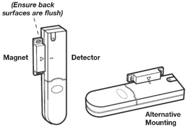
- If fixing the detector with screws first remove the battery holder by carefully tilting up the end and pulling away from the printed circuit board.

The top of the detector is secured with a keyhole slot over the head of the smaller pan head screw and the bottom of the detector is secured using the 12mm counter-sunk head screw fitted within the battery compartment. Carefully drill out the centre of the fixing screw hole in the battery compartment using a 3mm drill. Fit the magnet using the two 15mm fixing screws. Do not over tighten the fixing screws as this may distort or damage the casing.
- If an additional wired Magnetic Contact is required, this should be wired to the terminal block provided in the battery compartment. The wired contact should be connected using two core (24AWG) wire of maximum length 1.5m. A cable entry cut-out is provided beside the terminal block in the battery cover.
If an additional wired contact is connected to the detector then jumper link S2 on the PCB must be removed.
IMPORTANT: If an additional wired contact is not connected, then the jumper link S2 must be fitted for the detector to operate correctly.

- Configure the House Code for the Magnetic Contact Detector by setting DIP switches 1-8 to the same ON/OFF combination as the House Code DIP switches in all other system devices.
- Configure the alarm zone which the detector will operate on with DIP switches 9-11 as follows:
| DIP 9 DIP | 10 DIP 11 | ||
| Zone 1 OFF OFF OFF | |||
| Zone 2 OFF OFF ON | |||
| Zone 3 OFF ON OFF | |||
| Zone 4 OFF ON ON | |||
| Zone 5 ON OFF OFF | |||
| Zone 6 ON OFF ON | |||
e.g. To configure the detector to operate on Zone 2 set DIP switches 9, 10 and 11 as follows:

Note: DIP switch 12 is not used.
- Slide the two batteries supplied into the battery holder, ensuring that the positive (+) side is uppermost on each battery as it is installed.
- If necessary, refit the battery holder into the detector ensuring that the spring clip connectors slide onto either side of the circuit board.
- Refit the battery cover.
TESTING THE MAGNETIC CONTACT DETECTORS
Ensure that the system is in Test mode (see page 20).
- Use the ↑ and ↓ buttons to scroll through the menu until 'WALK TEST' is displayed and press ENTER .
'Walk Test Waiting...' will be displayed.
- Remove the battery cover from the Detector.
The LED on the Detector will illuminate for approx 1s as the battery cover is removed and the tamper switch is activated. In addition, the Control Panel will beep to indicate that an alarm signal has been received and ‘Accessory Tamper’ will be displayed.
- Open the door/window to remove the magnet from the Detector.
As the magnet is moved away from the detector the LED will illuminate for approx. 1s to indicate that the Detector has been triggered. In addition, the Control Panel will beep to indicate that an alarm signal has been received and the identity of the zone that the detector is configured for will be displayed.
Note: In normal operation with the battery cover fitted, the LED on the detector will not illuminate when the detector is triggered, (unless the battery is low).
- If any external Magnetic Contact Sets are connected to the Detector, operate these one at a time. Each time a contact is opened the LED on the Detector should illuminate for 1s to indicate that it has been triggered and the Control Panel will acknowledge the alarm signal.
- Replace the battery cover on the Detector.
- Press ESC to return to the top level menu of TEST MODE.
The Siren and Solar Panel are all encapsulated within a tough polycarbonate housing. This housing provides full protection against adverse weather conditions.
An LED indicator unit is built into the siren to act as a visible deterrent/indication that the system is active. The Strobe LEDs will slowly and alternately flash whether the system is Armed or Disarmed. During an alarm condition the Strobe LEDs will flash rapidly.
An integral anti-tamper switch provides additional security protection to the Siren and will immediately generate a full alarm should any unauthorised attempt be made to interfere with and remove the siren cover.
The Siren is powered by a high capacity 6V/1.2Ahr rechargeable sealed lead acid battery. A Solar Panel mounted on the top of the housing charges the battery during daylight hours. During darkness, only a small amount of energy is required to operate the Siren unit. A 9V Alkaline PP3 battery is supplied in the External Siren to boost the initial power to the unit when the system is first activated until the Solar Panel charges the main battery. (This battery is only designed to last for a short period until the main rechargeable battery has obtained sufficient charge).
The Siren unit incorporates the installations Jamming Detection system which will (if activated) generate an alarm if any attempt is made to continuously jam the radio channel used for the system.
POSITIONING THE SOLAR SIREN
The Siren should be located as high as possible in a prominent position so that it can be easily seen and heard. The Siren should be mounted on a sound flat surface so that the rear tamper switch is not activated when mounted. Ensure that the tamper switch does not fall into the recess between brick courses as this could prevent the switch from closing and give a permanent tamper signal.
In order to provide the maximum amount of daylight to the Solar Panel, the siren should ideally be mounted on a south facing wall. However, an easterly or westerly position will suffice.
Mounting the device on a north facing wall should be avoided as this could mean that during the short dark days of winter months the solar panel may not receive sufficient daylight in order to maintain the battery charge at acceptable levels.

flowchart
graph TD
    A["NORTH"] -->|Avoid if possible| B["Central Block"]
    B --> C["EAST"]
    C --> D["SOUTH"]
    D --> E["WEST"]
    E --> A
    style A fill:#f9f,stroke:#333
    style B fill:#ccf,stroke:#333
    style C fill:#cfc,stroke:#333
    style D fill:#fcc,stroke:#333
    style E fill:#ffc,stroke:#333
Shadows cast by neighbouring walls, trees and roof overhangs should also be avoided. If the Siren is to be mounted below the eaves, it should be positioned a distance of at least twice the width of the eaves overhang below the eaves. Remember that in winter the sun is lower in the sky and you should avoid winter shadows where possible.
The External Solar Siren contains a sophisticated radio receiver. However, reception of radio signals can be affected by the presence of metallic objects within the vicinity of the Solar Siren. It is therefore important to mount the Solar Siren a minimum distance of 1m away from any external or internal metalwork, (i.e. drainpipes, gutters, radiators, mirrors etc).
Ensure that the position selected for the Siren is within effective range of the Control Panel, (refer to "Testing the Control Panel & Remote Control").
INSTALLING AND CONFIGURING THE SOLAR SIREN
Ensure that the system is in Test mode (see page 20).
-
Remove the fixing screw from the bottom edge of the Siren housing and carefully hinge off the front cover. All electronic components are housed within the front cover.
-
Hold the mounting plate in position and mark the positions of the four mounting holes. A spirit level placed on the casing will ensure a perfect level.
Drill four 6mm holes and fit the wall plugs
- Fit the two 30mm fixing screws in the top holes leaving approximately 10mm of the screw protruding.

Inside view of Solar Siren with exploded view under set-up panel
- Fit the top keyhole slots of the mounting plate over the screw heads. Remove the mounting plate and adjust the screws until they form a neat fit with the mounting plate with minimal movement.
- Secure the mounting plate in position using the two 25mm fixing screws in the bottom fixing holes.
- Ensure that the Solar Siren main configuration switch on the LED indicator board is set to "SIREN" for use with this alarm system.
Main Configuration Switch (in SIREN Position)

- Undo the 3 screws holding the DIP Switch Cover in place and remove the cover.
- Under the cover you will find a series of 9 DIP switches.

Note: When the Solar Siren is viewed as shown above (Solar panel at top) the DIP switches are 'upside down'.
-
DIP switches 1-8 are used to set the House Code for the Siren and must be set to the same ON/OFF combination as all other system devices.
-
If required the maximum length of time that the External Solar Siren will sound for when activated under an alarm condition may be limited to 3 minutes using DIP switch 9 as follows:
ON as Control Panel setting OFF 3 minutes
- The Solar Siren will acknowledge Disarm signals from the Remote Control and Service Mode signals by beeping. It is possible to disable these acknowledgement beeps if required by removing the jumper link P2 on the circuit board.
P2 fitted beep enabled P2 removed beep disabled
- If for any reason you need to disable the Siren, remove jumper link P3 on the circuit board. This will prevent the Siren from sounding during an alarm condition. However, the Siren will still beep to acknowledge signals from the Remote Control, (provided the beep feature is not disabled).
P3 fitted Siren enabled P3 removed Siren disabled
- To enable the Jamming Detect feature in the Solar Siren fit the jumper link taped to the cover of the Siren control unit across link pins P1 on the circuit board.
P1 fitted Jamming Detection enabled P1 removed Jamming Detection disabled
- Refit the DIP switch cover and replace the three cover fixing screws. Do not over tighten the screw as this could damage the thread.
- Connect the 9V PP3 initial power battery to the battery clip.
Connect the rechargeable battery to the charging leads. Connect the Red lead to the Red (+ve) terminal and the Black lead the Black (-ve) terminals. Both indicator LEDs will flash together in a single long flash to indicate that the unit is operational.
Important: Once the batteries have been connected, the Siren will be operational. It is important that the solar panel receives sufficient light to maintain the battery charge.
The Siren should not be operated repeatedly during installation and testing, as this will rapidly drain the battery. It is recommended that the Siren be left for at least 24 hours in order to charge the battery before the system is Armed.
- Press the anti tamper switch, both indicator LEDs will flash together four times.
- Hinge the front cover locating tabs over the top edge of the back plate and carefully push the base of the siren cover into place. Secure the Siren cover in place by refitting the fixing screw in the bottom edge of the cover. Do not over tighten the screw as this could damage the thread.
Important: Ensure that the rear tamper switch is closed when you fit the siren cover to the backplate (i.e. listen for the switch to click). If the switch does not close this will prevent the Solar Siren from operating correctly. If necessary, remove the siren cover again and adjust the screw on the backplate tamper plunger to ensure the switch closes when the Siren is secured in position.
- If fitted remove the protective film covering the Solar Panel.
TESTING THE SOLAR SIREN
Ensure that the system is in Test mode (see page 20).
-
Scroll through the top level Test Mode menu until 'ALARM TEST' is displayed and press ENTER.
-
Scroll through the menu until 'Wirefree Siren Test' is displayed and press ENTER.
- The Solar Siren should operate for a period of approximately 5s,
- Press ESC to exit Alarm Test and return to the top level Test Mode menu.
EXTERNAL CONNECTIONS

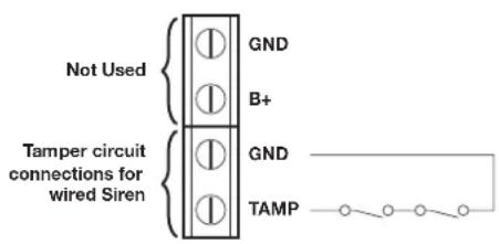
Terminal Block Detail
The Control Unit incorporates a terminal block for connection of hard-wired Zones (7-10) and a wired Siren. The connection terminal block is located inside the Control Panel behind the front cover. To access the terminal block:

This puts the system into Test Mode and prevents an alarm occurring.
Undo the two fixing screws on the top edge of the Control Panel and open the front cover.
Before making any connections, ensure that the memory jumper link P1 is in the 'OFF' position and
then remove the DC power jack and disconnect one of the back-up batteries.
The hardwired zone and tamper switches should be Volt free and Normally Closed, with the contacts opening in order to initiate an alarm.
Note: Jumper link P51 should be fitted into the ON position only if the external hardwired tamper circuit is used, otherwise it must be in the OFF position.
After making your external connections reconnect the power supply and Back-up Battery. Then close the Control Panel cover and tighten the fixing screws on the top edge of the Control Panel.
Press ESC to leave Test mode and return to Standby.
TESTING THE SYSTEM
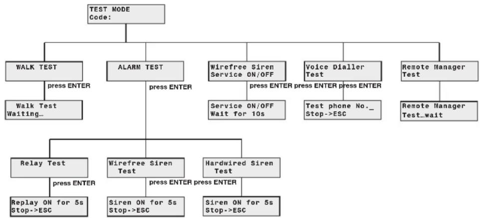
flowchart
graph TD
    A["TEST MODE Code:"] --> B["WALK TEST"]
    A --> C["ALARM TEST"]
    A --> D["Wirefree Siren Service ON/OFF"]
    A --> E["Voice Dialler Test"]
    A --> F["Remote Manager Test"]
    B --> G["press ENTER"]
    G --> H["Walk Test Waiting..."]
    C --> I["press ENTER"]
    I --> J["Service ON/OFF Wait for 10s"]
    C --> K["Test phone No._ Stop->ESC"]
    C --> L["Remote Manager Test...wait"]
    J --> M["Relay Test"]
    J --> N["Wirefree Siren Test"]
    J --> O["Hardwired Siren Test"]
    M --> P["press ENTER"]
    N --> Q["press ENTER press ENTER"]
    O --> R["Siren ON for 5s Stop->ESC"]
    O --> S["Siren ON for 5s Stop->ESC"]
    O --> T["Siren ON for 5s Stop->ESC"]
INITIAL TESTING
As the system is initially installed it is recommended that each device is tested in turn as it is installed, (refer to testing instructions for particular device).
TESTING AN INSTALLED SYSTEM
The Control Panel has a built in test facility to enable you to test the system at any time. However it is recommended that the system is tested at regular intervals not exceeding 3 months.
With the system in Standby Mode
Press


User Access Code
The Arm and Part-Arm LEDs will flash.
The system is now in the Test Mode
Use the

and

buttons to scroll through
the menu and press function or sub-me

to select the displayed test
Note: press

completing all required test functions to leave Test mode and return to Standby.
WALK TEST
Before commencing testing please ensure that there is no movement in any PIR protected area, all doors/windows protected by Magnetic Contact Detectors are closed and that all battery covers and housings are correctly fitted.
Scroll through the top level Test Mode menu until 'WALK TEST' is displayed and press ENTER.
'Walk Test Waiting...' will be displayed.
- T rigger each detector on the system by either walking into a PIR protected area or by opening a door/window protected by a Magnetic Contact detector. As each detector is triggered the Control Panel will beep to indicate that an alarm signal has been received and the identity of the zone that the detector is configured for will be displayed.
Note: To conserve power and maximise battery life the PIR detector will only detect movement if there has been no movement detected within the previous 2 minutes.
- Operate detector anti-tamper switches by opening the case of the device. As the switches are
operated the Control Panel will beep and 'Accessory Tamper' will be displayed.
- Activate each button on the Remote control in turn. As each button is pressed the Control panel will beep and the button name will be displayed, (e.g. 'REMOTE CONTROL DISARM').
Press to exit Walk Test and return to the top level Test Mode menu.
ALARM TEST
Scroll through the top level Test Mode menu until 'ALARM TEST' is displayed and press ENTER.
Scroll through the menu until the required alarm is displayed and press ENTER to operate the selected alarm for 5s.
Select 'Wirefree Siren Test' to operate the External Solar Siren.
Select 'Hardwired Siren Test' to operate the Control Panel Siren and external hardwired Siren (if connected).
Select 'Relay Test' to operate the External hardwired (N.O./N.C.) Relay contacts.
Press ESC to exit Alarm Test and return to the top level Test Mode menu.
SOLAR SIREN SERVICE MODE SWITCHING
The Siren includes a Service Mode facility which prevents the sirens tamper switch from triggering the siren while it is removed from the wall for maintenance or to change the batteries. After changing the batteries and refitting in position, the Siren must be put back into normal Operating Mode, otherwise the siren will not sound in the event of an alarm condition.
- Scroll through the top level Test Mode menu until "Wirefree Siren Service ON/OFF" is displayed.
Press to switch the solar siren between Operating and Service modes. The mode into which the siren is switching will be indicated as follows:
Service Mode: The Siren will produce two short beeps/LED flashes and then after approx 6s a single long beep/LED flash followed immediately by two short beeps/LED flashes to indicate that it
has switched into service mode.
Operating Mode: After approx 6s the Siren will produce a single long beep/LED flash to indicate that it has switched into normal operating mode
- Press ESC to exit Solar Siren Service Mode Switching and return to the top level Test Mode menu.
VOICE DIALLER TEST
-
Scroll through the top level Test Mode menu until 'VOICE DIALER TEST' is displayed and press ENTER .
-
If the Voice Dialer is enabled then it will be activated and will follow the normal calling process. It will call each enabled number in the dialling sequence the set number of times with the main and Intruder alarm messages will be replayed to the called number.
The test sequence may be cancelled either at the Control Panel by pressing ESC or by the call recipient pressing the * button on their telephone keypad.
- Press ESC to exit Alarm Test and return to the top level Test Mode menu
REMOTE MANAGER TEST
-
Scroll through the top level Test Mode menu until 'REMOTE MANAGER TEST' is displayed and press ENTER .
-
If the Remote Manager is enabled then it will be activated and a test call will be placed to the Remote Alarm Monitoring Service provider.
If an acknowledgment signal is not received then a failure message will be displayed on the screen. In this event the system configuration for the Remote Manager should be checked in conjunction with the Alarm Monitoring Service provider.
- Press ESC to exit Alarm Test and return to the top level Test Mode menu.
DEFAULT SETTINGS
User Setup
| Users 1-6: Not programmed |
| Master User Access Code: 1234 |
System Setup
| House Code: Not programmed | |
| Alarm Time: ON, 180s | |
| Wirefree Siren: ON | |
| RF Jamming Detection: OFF | |
| Back Light: 10s | |
| Alarm Relay: On Until Disarm | |
| Zone Lockout: ON | |
| Remote Phone Control: OFF | |
| Rings to Answer Phone: 6 | |
| Dial Delay: ON | |
| Dial method: | Tone/DTMF |
| Dialler Mode: | Voice Dialler |
Zone Setup (Z1-10)
| Name: | No Name | |
| Type: | Intruder | |
| Final Exit: | OFF | |
| Chime: | OFF | |
| Entry Delay | Zone 1: | ON, 30s |
| Zones 2-10: | OFF | |
| Part-Arm 1 | Zones 1-4: | ON |
| Zones 5-10: | OFF | |
| Part-Arm 2: | OFF | |
| Walk Through: OFF | ||
Voice Dialler Setup
| Phone Numbers: | Not programmed |
| Message Play Time: | 70s |
| Alarm Messages: | Not programmed |
| Call Routing: | All numbers disabled |
| Call Confirms: | 1 |
| Call Attempts: | 3 |
Full Arm Setup
| Exit Delay: ON, 30s | |
| Entry Delay Beep: | ON |
| Exit Delay Beep: | ON |
Part-Arm 1 Setup
| Exit Delay: ON, 30s | |
| Entry Delay Beep: | ON |
| Exit Delay Beep: | ON |
Part-Arm 2 Setup
| Exit Delay: ON, 30s | |
| Entry Delay Beep: | ON |
| Exit Delay Beep: | ON |
Time & Date
| Time: | 12:00:00 |
| Date: | 01/01/02 |
Latchkey Setup
| Status: | OFF |
| Selected User Setup: | OFF (all users) |
| Phone Numbers: | Not programmed |
Answer Phone Setup
| Status: | OFF |
| Greeting Message: | Not programmed |
Remote Manager Setup
| Phone No: | Not programmed |
| Unit ID No: | Not programmed |
| Call Attempts: | 3 |
RESET FACTORY DEFAULT CONDITIONS
- Pre s s

This puts the system into Test Mode.
- Undo the Control Panel cover fixing screws and open the cover.
- Remove the DC power jack, then remove and disconnect one of the back-up batteries.
- Set jumper link P1 to the ON position.

- Reconnect the power supply jack.
- The Control Panel will now reconfigure itself with all factory default settings.
'EEPROM RESET' will be displayed while the defaults are restored to memory. Once the memory reset has been completed 'DISARM READY' will be displayed.
- Reconnect and replace the back-up battery.
- Reset jumper link P1 into the OFF position.
- Close the Control Panel cover and refit the fixing screws.
PROGRAMMING INSTRUCTIONS
With the system in Standby Mode.
Press

The system is now in the Programming Mode
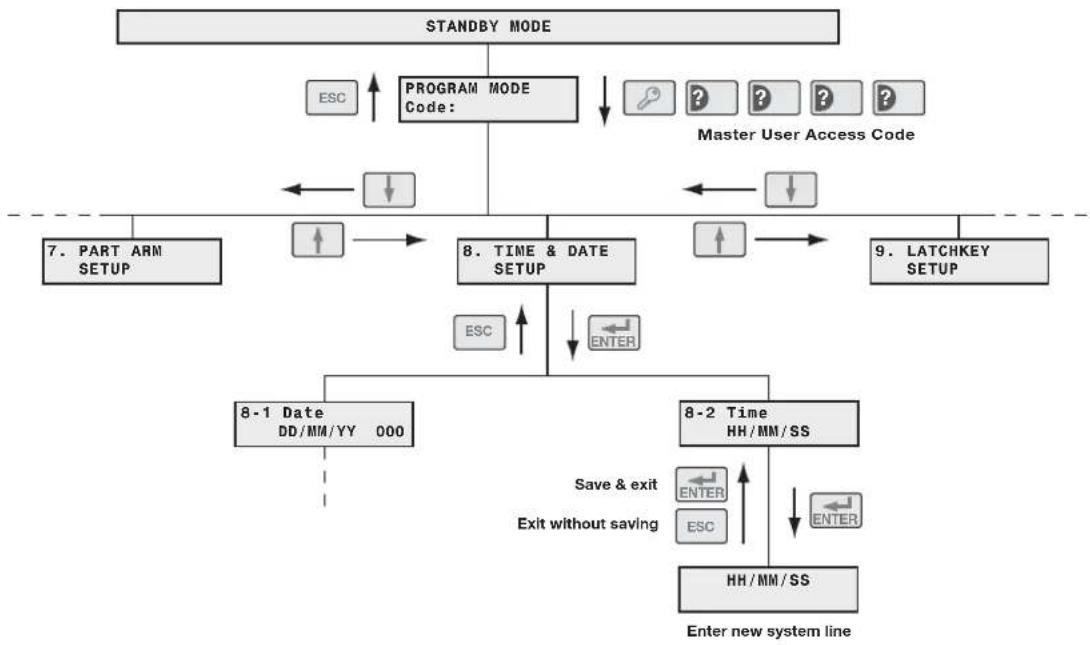
flowchart
graph TD
    A["STANDBY MODE"] --> B["PROGRAM MODE Code:"]
    B --> C["Master User Access Code"]
    C --> D["8. TIME & DATE SETUP"]
    D --> E["8-1 Date DD/MM/YY 000"]
    D --> F["8-2 Time HH/MM/SS"]
    E --> G["Enter new system line"]
    F --> H["Enter without saving"]
    G --> I["ESC"]
    H --> J["ESC"]
    I --> K["ESC"]
    J --> L["ESC"]
    K --> M["ESC"]
    L --> N["ESC"]
    M --> O["ESC"]
    N --> P["ESC"]
    O --> Q["ESC"]
    P --> R["ESC"]
    Q --> S["ESC"]
    R --> T["ESC"]
    S --> U["ESC"]
    T --> V["ESC"]
    U --> W["ESC"]
    V --> X["ESC"]
    W --> Y["ESC"]
    X --> Z["ESC"]
    Y --> AA["ESC"]
    Z --> AB["ESC"]
    AA --> AC["ESC"]
    AB --> AD["ESC"]
    AC --> AE["ESC"]
    AD --> AF["ESC"]
    AE --> AG["ESC"]
    AF --> AH["ESC"]
    AG --> AI["ESC"]
    AH --> AJ["ESC"]
    AI --> AK["ESC"]
    AJ --> AL["ESC"]
    AK --> AM["ESC"]
    AL --> AN["ESC"]
    AM --> AO["ESC"]
    AN --> AP["ESC"]
    AO --> AQ["ESC"]
    AP --> AR["ESC"]
    AQ --> AS["ESC"]
    AR --> AT["ESC"]
Navigating through the Programming Mode Menus
The programmable system parameters are arranged by groups in a series of menus within programming mode.
Each menu (and sub-menu) will contain all programmable system parameters related to the particular function.
Note: Some basic system parameters will be contained within the system menu because they related to a number of different functions.
At each menu level, use the ↑ and ↓ buttons to scroll through the available options.
Note: A menu item displayed in full capitals (e.g. 'FULL ARM SETUP') indicates that there is another menu below that option. An option displayed in lower case (e.g. '5.2 Entry Delay Beep') indicates that this is a parameter setting and no menu below, (although there may be setting options).
Press ENTER to
a) select the displayed menu, or
b) change the displayed parameter setting, or
c) save the changed parameter setting and revert to the previous level
Press ESC to
a) exit to the previous menu level, or
b) revert to the previous level without saving a changed parameter setting.
Note: After programming all required functions press ESC to leave Programming mode and return to Standby.
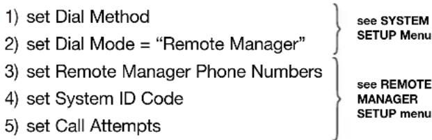
Telephone Application Setup
If using any of the telephone based functionality, (e.g. answer-phone voice dialler, remote phone access & control etc) the dial method must be set according to the exchange type, (i.e. Pulse or Tone/DTMF).
Voice Dialler

Remote Manager
Answer-Phone

Latch Key

USER SETUP
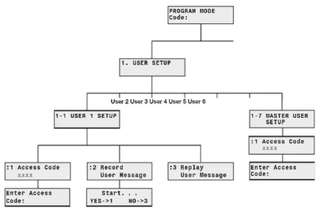
flowchart
graph TD
    A["PROGRAM MODE Code:"] --> B["1. USER SETUP"]
    B --> C["User 2 User 3 User 4 User 5 User 6"]
    B --> D["1-1 USER 1 SETUP"]
    B --> E["1-7 MASTER USER SETUP"]
    D --> F[":1 Access Code XXXX"]
    D --> G[":2 Record User Message"]
    D --> H[":3 Replay User Message"]
    E --> I[":1 Access Code XXXX"]
    E --> J["Enter Access Code:"]
    F --> K["Enter Access Code:"]
    G --> L["Start... YES->1 NO->3"]
This menu allows the 4 digit user access codes to be configured for each User. The general users (1-6) may also record a 4s message to be used with the "Latch-Key" feature.
Note: For the Latch-Key feature to operate correctly the "Dial Method" (see system setup) and the items within the Latch-Key Setup menu must be correctly set and programmed.
Scroll through the top level programming menu until '1. USER SETUP' is displayed and press ENTER.
Note: After configuring all required users press to return to the top level of programming menu.
USERS 1-6
Default setting: not programmed
Scroll through the menu until the required User 'USER _ SETUP' is displayed and press ENTER.
User Access Code
Scroll through the menu until ‘:1 Access Code’ (and the current setting) is displayed.
Tochange the setting press ENTER.
Enter the new 4 digit Access Code and then
Press ENTER to save and exit, or
Press ESC to exit without saving.
Record User Latch-Key Message
This enables each User to record a short 4s message for use with the Latch Key facility. e.g. "system disarmed by User-1".
Scroll through the menu until ‘:2 Record User Message’ is displayed.
Torecord a new message press ENTER.
Press 1 to start the voice recorder
When recording, press ESC to stop the recorder and cancel any remaining recording time. The new message will then be replayed.
Press 3 to exit without changing.
Replay User Latch-Key Message
Scroll through the menu until ‘:3 Replay User Message’ is displayed and press ENTER to replay the message.
Press ESC to return to the top level User-Setup menu.
MASTER USER
Default Access Code: 1234
Scroll through menu until '1-7 MASTER USER SETUP' is displayed and press ENTER.
Scroll through the menu until ‘:1 Access Code’ (and the current setting) is displayed.
Tochange the setting press ENTER.
Type in a new 4 digit Access Code, and then
Press ENTER to start the voice recorder
Press ESC to start the voice recorder
Press ESC to return to the top level User-Setup menu.
SYSTEM SETUP
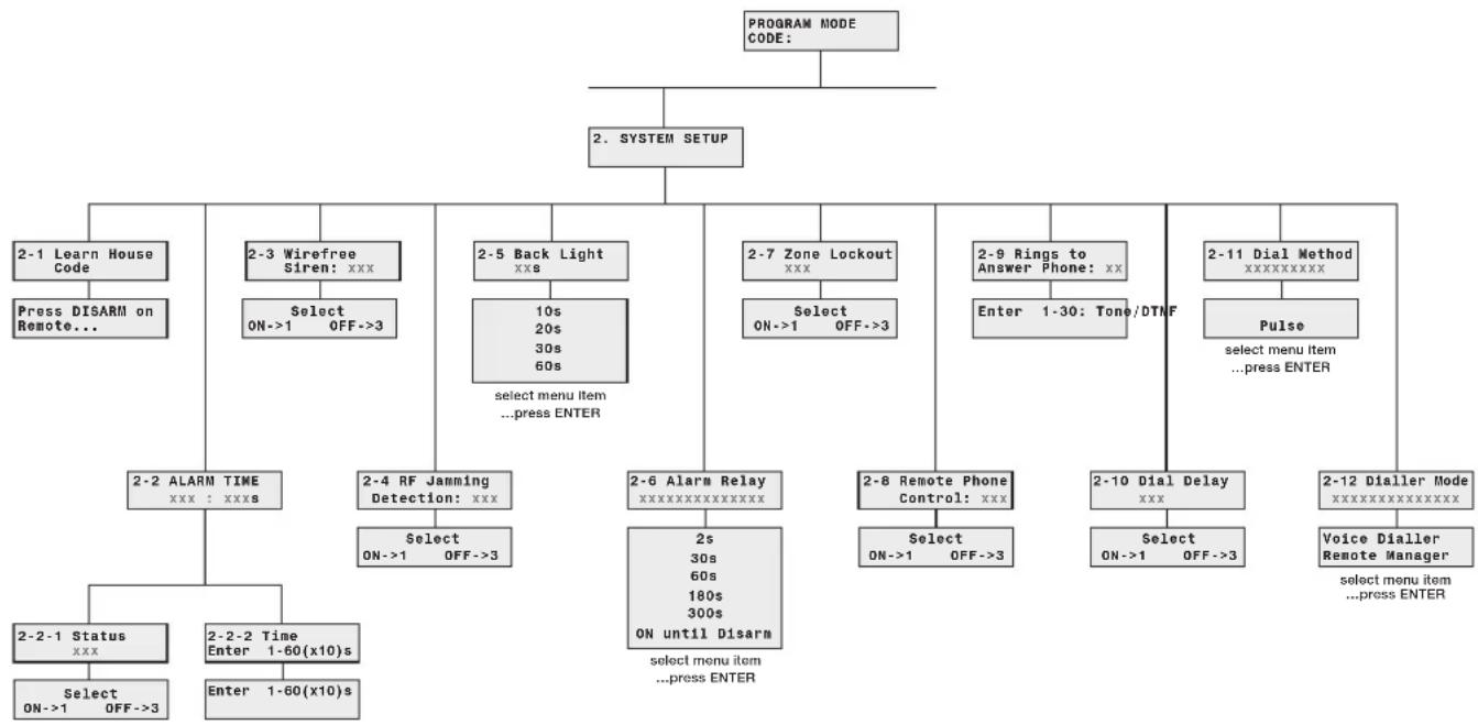
The parameters in this menu allow the configuration of the general system parameters, such as the control panel house code, alarm duration and control of any hardwired or output relay alarm contacts. This section also contains the basic setup information for the systems telephone dialler interface which must be configured appropriately if any of the telephone based functionality is to be used.
flowchart
graph TD
    A["PROGRAM MODE CODE:"] --> B["2. SYSTEM SETUP"]
    B --> C["2-1 Learn House Code"]
    B --> D["2-3 Wirefree Siren: xxx"]
    B --> E["2-5 Back Light xxs"]
    B --> F["2-7 Zone Lockout xxx"]
    B --> G["2-9 Rings to Answer Phone: xx"]
    B --> H["2-11 Dial Method xxxxxxxxxxxx"]
    C --> I["Press DISARM on Remote..."]
    D --> J["Select ON->1 OFF->3"]
    E --> K["10s 20s 30s 60s"]
    F --> L["Select ON->1 OFF->3"]
    G --> M["Enter 1-30: Tone/DTNF"]
    H --> N["Pulse"]
    I --> O["2-2 ALARM TIME xxx : xxxs"]
    J --> P["2-4 RF Jamming Detection: xxx"]
    K --> Q["2-6 Alarm Relay xxxxxxxxxxxxxxxx"]
    L --> R["2-8 Remote Phone Control: xxx"]
    M --> S["2-10 Dial Delay xxx"]
    N --> T["Pulse"]
    O --> U["Select menu item ...press ENTER"]
    P --> V["Select menu item ...press ENTER"]
    Q --> W["Select menu item ...press ENTER"]
    R --> X["Select menu item ...press ENTER"]
    S --> Y["Select menu item ...press ENTER"]
    T --> Z["Voice Dialler Remote Manager select menu item ...press ENTER"]
    U --> AA["Select menu item ...press ENTER"]
    V --> AB["Select menu item ...press ENTER"]
    W --> AC["Select menu item ...press ENTER"]
    X --> AD["Select menu item ...press ENTER"]
Scroll through the top level programming menu until '2. SYSTEM SETUP' is displayed and press

Note: After completing the system setup press
ESC to return to the top level programming menu.
Scroll through the menu until '2-1 Learn House Code' is displayed.
Tochange the setting press ENTER.
The current House code setting will be displayed. The new system House Code can be programmed either directly at the Control Panel or via a Remote Control Unit.
At the Control Panel
Press buttons 1-8 on the Control Panel to configure the display to the correct house code setting. As each button is pressed the corresponding digit in the code will change to the opposite state, ("0" or "1").
1 = House Code DIP Switch On/Up
0 = House Code DIP Switch Off/Down
Using a Remote Control
With the required House Code already configured, press the button on the Remote Control.
When the Control Panel receives the signal from the Remote Control the Panel will beep and the display will change to show the received house code on lower line of the display beneath the corresponding DIP switch numbers (1-8).
Press ENTER to save the new setting, or
Press ESC to exit without saving.
Note: Make a note of the system house code now in the Alarm Record section.
ALARM DURATION
Scroll through the menu until '2-2 ALARM TIME' (and the current setting) is displayed.
Tochange the setting press ENTER.
On/Off Status
Default setting: ON
Scroll through the menu until '2-2-1 Status' (and the current setting) is displayed.
Tochange the setting press ENTER.
Press 1 to enable the Siren, or Press 3 to disable the Siren.
Siren Duration
Default setting: 180s
Scroll through the menu until '2-1-2 Time' (and the current setting) is displayed.
Tochange the setting press ENTER.
Enter the required alarm duration in units of 10s. e.g. enter 6 for a 60s alarm duration (max setting 60, i.e. 600s/10mins).
Press ENTER to save and exit, or
Press ESC to exit without saving.
Press ESC to return to top level System Setup menu.
Note: Following an alarm condition the Siren will continue to sound until either the system is Disarmed; or the Alarm Duration Time expires. If the "3 minute alarm time limit" of the Solar Siren is enabled then the Solar Siren will shut down after 3 minutes even if the panel siren is still operating.
WREFREE SIREN
Allows the wirefree siren to be enabled or disabled.
Default setting: ON
Scroll through the menu until '2-3 Wirefree Siren' (and the current setting) is displayed.
Tochange the setting press ENTER.
Press 1 to enable the Solar Siren, or Press 3 to disable the Solar Siren.
JAMMING DETECTION
Allows the jamming detection in the control panel to be enabled or disabled.
Default setting: OFF
Scroll through the menu until '2-4 RF Jamming Detection' (and the current setting) is displayed.
Tochange the setting press ENTER.
Press 1 to enable Jamming Detection, or Press 3 to disable Jamming Detection.
This controls how long the display backlight will remain illuminated for after a key is pressed.
Default setting: 10s
Scroll through the menu until '2-5 Back Light' (and the current setting) is displayed.
Tochange the setting press ENTER.
Press ENTER to save and exit, or
Press ESC to exit without saving.
ALARM RELAY
This controls the operation of the NO/NC hardwired output relay contacts following an alarm.
Default setting: "ON Until Disarm
Scroll through the menu until '2-6 Alarm Relay' (and the current setting) is displayed.
Tochange the setting press ENTER.
Scroll through the menu options, until the required setting is displayed.
Press ENTER to save and exit, or
Press ESC to exit without saving.
ZONE LOCKOUT
If enabled, this prevents a single zone from triggering an alarm condition more than three times before the system is disarmed.
Default setting: ON
Scroll through the menu until '2-7 Zone Lockout' (and the current setting) is displayed.
Tochange the setting press ENTER.
Press 1 to enable Zone Lockout, or
Press 3 to disable Zone Lockout.
REMOTE PHONE ACCESS AND CONTROL
If enabled, this allows the system to be remotely controlled via the telephone.
Default setting: OFF
Scroll through the menu until '2-8 Remote Phone Control' (and the current setting) is displayed.
Tochange the setting press ENTER.
Press 1 to enable Remote Phone Control, or
Press 3 to disable Remote Phone Control.
RINGS TO ANSWER PHONE
This sets the number of rings which occur before the Control Panel will "pick up" the call to operate with the answer-phone or Remote Phone Access features.
Default setting: 6
Scroll through the menu until '2-9 Rings To Answer Phone' (and the current setting) is displayed.
Tochange the setting press ENTER.
Enter the required number of rings (1-30).
Press ENTER to save and exit, or
Press ESC to exit without saving.
DIALLER DELAY
If enabled, this delays the activation of the telephone dialer following an alarm for a period of approx 30s to allow the system to be disarmed.
Default setting: ON
Scroll through the menu until '2-10 Dial Delay' (and the current setting) is displayed.
Tochange the setting press ENTER.
Press 1 to enable the dialler delay, or
Press 3 to disable the dialler delay.
DIAL METHOD
This enables the telephone dialler to be configured for type of exchange it is connected to. (Most exchanges are now Tone/DTMF systems.
Default setting: Tone/DTMF
Scroll through the menu until '2-11 Dial Method' (and the current setting) is displayed.
Tochange the setting press ENTER.
Scroll through the menu options, until the required setting is displayed.
Press ENTER to save and exit, or
Press ESC to exit without saving.
DIAL MODE
This controls whether the telephone dialler operates with the voice dialler or Remote Security Monitoring service.
Default setting: Voice Dialler
Scroll through the menu until '2-12 Dialer mode' (and the current setting) is displayed.
Tochange the setting press ENTER.
Scroll through the menu options, until the required setting is displayed.
Press ENTER to save and exit, or
Press ESC to exit without saving.
ZONE SETUP
The parameters in this menu allow each zones specific function to be configured.
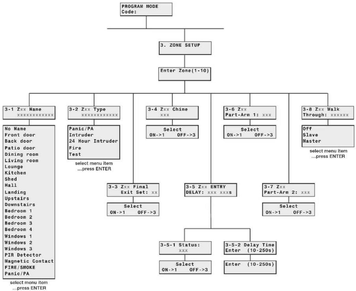
flowchart
graph TD
    A["PROGRAM MODE Code:"] --> B["3. ZONE SETUP"]
    B --> C["Enter Zone(1-10)"]
    C --> D["3-1 Zxx Name xxxxxxxxxxxx"]
    C --> E["3-2 Zxx Type xxxxxxxxxxxx"]
    C --> F["3-4 Zxx Chime xxx"]
    C --> G["3-6 Zxx Part-Arm 1: xxx"]
    C --> H["3-8 Zxx Walk Through: xxxxxx"]
    D --> I["No Name"]
    D --> J["Front door"]
    D --> K["Back door"]
    D --> L["Patio door"]
    D --> M["Dining room"]
    D --> N["Living room"]
    D --> O["Lounge"]
    D --> P["Kitchen"]
    D --> Q["Shed"]
    D --> R["Hall"]
    D --> S["Landing"]
    D --> T["Upstairs"]
    D --> U["Downstairs"]
    D --> V["Bedroom 1"]
    D --> W["Bedroom 2"]
    D --> X["Bedroom 3"]
    D --> Y["Bedroom 4"]
    D --> Z["Windows 1"]
    D --> AA["Windows 2"]
    D --> AB["Windows 3"]
    D --> AC["PIR Detector"]
    D --> AD["Magnetic Contact"]
    D --> AE["FIRE/SMOKE"]
    D --> AF["Panic/PA"]
    E --> AG["Select menu item ...press ENTER"]
    F --> AH["Select ON->1 OFF->3"]
    G --> AI["Select ON->1 OFF->3"]
    H --> AJ["Off Slave Master select menu item ...press ENTER"]
    I --> AK["3-3 Zxx Final Exit Set: xx"]
    AK --> AL["Select ON->1 OFF->3"]
    J --> AM["3-5 Zxx ENTRY DELAY: xxx xxxs"]
    K --> AN["3-7 Zxx Part-Arm 2: xxx"]
    AL --> AO["Select ON->1 OFF->3"]
    AM --> AP["3-5-1 Status: xxx"]
    AN --> AQ["Select ON->1 OFF->3"]
    AP --> AR["3-5-2 Delay Time Enter (10-250s)"]
    AQ --> AS["Enter (10-250s)"]
Scroll through the programming menu until '3. ZONE SETUP' is displayed and press ENTER .
Enter the zone number to be configured and press ENTER.
The following configuration options are based upon configuring zone 1. Options for all other zones (2-10) are identical except the zone number reference will change according to the zone being configured.
Note: After completing the Zone Setup press to return to the top level programming menu.
NAME
This enables a name to be allocated to the zone so it can be identified by its location.
Default setting: 'No Name'
Scroll through the menu until '3-1 Z01 Name' (and the current setting) is displayed.
Tochange the setting press ENTER.
Scroll through the menu options until the required setting is displayed.
Press ENTER to save and exit, or
Press ESC to exit without saving.
TYPE
Each zone may be programmed to operate in one of 5 different modes dependant upon the type of alarm function required. The following types are available.
Panic/PA
- used to provide 24 hour monitoring of any Personal Attack (PA) switches fitted to the system. Activation of any PA switch will immediately initiate an alarm.
Intruder
- provides standard intruder monitoring.
24 Hour Intruder
- used to provide 24 hour monitoring of areas requiring continuous security protection even while the system is Disarmed, (e.g. gun lockers). Activation of any detector on a security zone will immediately initiate an alarm.
Fire
- use to provide 24 hour monitoring of any Fire/Smoke detectors fitted to the system. Activation of any detector will immediately initiate an alarm.
Test
- when the system is armed, any detector on the zone will generate an entry in the Event-Log without initiating an alarm.
Note: Personal Attack, 24 Hour Intruder and Fire modes all operate on a 24 hour basis, (i.e. they are able to initiate an alarm at any time even if the system is Disarmed).
Default setting: 'Intruder'
Scroll through the menu until '3-2 Z01 Type' (and the current setting) is displayed.
Tochange the setting press ENTER.
Scroll through the menu options until the required setting is displayed.
Press ENTER to save and exit, or
Press ESC to exit without saving.
FINAL EXIT SET
This controls whether the zone will trigger the systems final exit set feature. Triggering a detector on a “final Exit Set Zone” during the exit-delay will reset the remaining exit-delay to 5s.
Default setting: OFF
Scroll through the menu until '3-3 Z01 Final Exit Set' (and the current setting) is displayed.
Tochange the setting press ENTER.
Press 1 to enable the zone's Final Exit Set facility, or
Press 3 to disable the zone's Final Exit Set facility.
CHIME
This controls whether the zone will operate with Chime Mode.
Default setting: OFF
Scroll through the menu until '3-4 Z01 Chime' (and the current setting) is displayed.
Tochange the setting press ENTER.
Press 1 to enable the zone in Chime Mode, or
Press 3 to disable the zone in Chime Mode.
ENTRY DELAY
Scroll through the menu until '3-5 ENTRY DELAY' (and the current setting) is displayed.
Tochange the setting press ENTER.
On/Off Status
Default setting: zone 1: ON zones 2-10: OFF
Scroll through the menu until '3-5-1 Status' (and the current setting) is displayed.
Tochange the setting press ENTER.
Press 1 to enable the zones entry-delay, or
Press 3 to disable the zone's entry-delay.
Delay Period
Default setting: 30s
Scroll through the menu until '3-5-2 Delay Time' (and the current setting) is displayed.
Tochange the setting press ENTER.
Enter the required delay period (10 to 250s).
Press ENTER to save and exit, or
Press ESC to exit without saving.
Press ESC to return to top level Zone Setup menu.
PART-ARM 1
This controls whether the zone is active when Part-Arm 1 is armed.
PART-ARM 1
This controls whether the zone is active when Part-Arm 1 is armed.
Default setting: zones 1-4: OFF
zones 5-10: ON
Scroll through the menu until '3-6 Z01 Part-Arm 1' (and the current setting) is displayed.
Tochange the setting press

Press

to enable the Zone in Part-Arm 1, or
Press

to disable the Zone in Part-Arm 1.
PART-ARM 2
This controls whether the zone is active when Part-Arm 2 is armed.
Default setting: OFF (all zones)
Scroll through the menu until '3-6 Z01 Part-Arm 2' (and the current setting) is displayed.
Tochange the setting press ENTER.
Press

to enable the Zone in Part-Arm 2, or
Press

to disable the Zone in Part-Arm 2.
WALK THROUGH
This controls whether the zone operates with the systems "Walk Through" feature and determines if the zone is the entry-door or is on the entry-route.
Default setting: OFF
Scroll through the menu until '3-8 Z01 Walk Through' (and the current setting is displayed.
Tochange the setting press

Press

to enable the Zone in Part-Arm 2, or
Press

to disable the Zone in Part-Arm 2.
VOICE DIALLER SETUP
The parameters in this menu allow the configuration of the systems voice dialler. It allows up to four phone numbers to be entered and the call routing sequence to be configured by defining which number are called and the number of attempts made to contact each number. The alarm voice messages are also recorded here.
Note: For the Voice Dialer to operate correctly the "Dial Method" and "Dialer Mode" (see system setup) must be correctly set and programmed.

flowchart
graph TD
    A["PROGRAM MODE Code:"] --> B["4. VOICE DIALER SETUP"]
    B --> C["4-1 PHONE NUMBERS"]
    B --> D["4-2 Message Play Time: XXXs"]
    B --> E["4-3 RECORD ALARM MESSAGES"]
    B --> F["4-4 REPLAY ALARM MESSAGES"]
    B --> G["4-5 CALL ROUTING XXXX"]
    B --> H["4-7 Call Attempts: X"]
    C --> I["Phone No.2"]
    C --> J["Phone No.3"]
    I --> K["Enter Phone No:"]
    J --> L["4-1-1 Phone No.1 xxxxxxxxxxxx"]
    J --> M["4-1-4 Phone No.4 xxxxxxxxxxxx"]
    L --> N["Enter Phone No:"]
    F --> O["4-4-1 Main + Intruder Message"]
    F --> P["4-4-3 Main + Panic/PA Message"]
    G --> Q["4-6 Tel Confirm Times: X"]
    G --> R["Enter 1-4:"]
    O --> S["Phone No.2 Phone No.3"]
    S --> T["Select ON->1 OFF->3"]
    T --> U["4-5-1 Phone No.1 xxx"]
    T --> V["4-5-4 Phone No.4 xxx"]
    U --> W["Start... YES->1 NO->3"]
    V --> X["Start... YES->1 NO->3"]
    W --> Y["4-3-1 Main Alarm Messages"]
    W --> Z["4-3-2 Intruder Alarm Messages"]
    W --> AA["4-3-3 Fire Alarm Messages"]
    W --> AB["4-3-4 Panic/PA Alarm Messages"]
Scroll through the programming menu until '4. VOICE DIALER SETUP' is displayed and press ENTER.
Note: After completing the Voice Dialer Setup press to return to the top level programming menu.
TELEPHONE NUMBERS
Scroll through the menu until '4-1 PHONE NUMBERS' is displayed and press ENTER.
Scroll through the menu until the required 'Phone No._' (and the current setting) is displayed.
Tochange the number press ← ENTER .
Enter the new phone number (32 digits max).
Notes:
Press 📄 to insert a 3.5s pause in the dialling sequence.
Press to move the cursor left.
Press to move the cursor right.
Press to delete the number under the cursor.
Press (and hold) to erase the entire number.
Press ENTER to save and exit, or
Press ESC to exit without saving.
After programming all required phone numbers press ESC to return to the top level Voice Dialer menu.
ALARM MESSAGE PLAY TIME
This is the total time for which the alarm messages will be played & repeated by the voice dialler.
Default setting: 70s
Scroll through the menu until '4-2 Message Play Time' (and the current setting) is displayed.
Tochange the settings press ENTER.
Scroll through the menu options until the required setting is displayed.
Press ENTER to enable the Zone in Part-Arm 2, or Press ESC to disable the Zone in Part-Arm 2.
RECORD ALARM MESSAGES
Scroll through the menu until '4-3 RECORD ALARM MESSAGES' is displayed and press ENTER.
Scroll through the available menu options until the required message to be recorded is displayed
a) Main message, (12s max).
b) Intruder Alarm message, (4s max).
c) Fire Alarm message, (4s max).
d) Panic/PA Alarm message, (4s max).
Torecord a new message press ENTER.
Press 1 to start the voice recorder
When recording, press ESC to stop the recorder and cancel any remaining recording time. The new message will then be replayed.
Press 3 to exit without changing.
Press ESC to return to the top level Voice Dialler setup menu.
REPLAY ALARM MESSAGES
Scroll through the menu until '4-4 REPLAY ALARM MESSAGES' is displayed and press ENTER.
Scroll through the menu options until the required message is displayed and press ENTER to replay the message.
Press ESC to return to the top level Voice Dialler setup menu.
CALL ROUTING
This controls which phone numbers in the dialling sequence are enabled and will be called when the voice dialler is activated.
Default setting: all numbers disabled
Scroll through the menu until '4-5 CALL ROUTING' (and the current setting) is displayed.
The status if each phone number is displayed in order with an 'x' indicating that the number is disabled and a '1' indicating an enabled number. (e.g. A display of "OOOx" indicates an active call sequence of phone numbers: 1, 2 and 3. Phone number 4 is disabled and will not be called).
To change the setting press ENTER .
Scroll through the menu until the required 'Phone No._' (and the current setting) is displayed.
Tochange the setting press ENTER.
Press

to enable the phone number, or
Press

to disable the phone number.
Press ESC to return to the top level Voice Dialler Setup menu.
TEL CONFIRM TIMES
This sets the number of acknowledged phone numbers required to stop the voice dialler. (For example, if set to "2" then the dialler sequence will continue until an acknowledgment signal is received from two different numbers.
Default setting: 1
Scroll through the menu until '4-6 Tel Confirm Times' (and the current setting) is displayed.
Tochange the setting press ENTER.
Enter the required number of confirmations (1-4).
Press

to save and exit, or
Press

to exit without saving.
CALL ATTEMPTS
This sets the maximum number of times that the dialler will attempt to contact each enabled telephone number in the call routing sequence.
Default setting: 3
Scroll through the menu until '4-7 Call Attempts' (and the current setting) is displayed.
Tochange the setting press ENTER.
Enter the required number of dial attempts (1-5).
Press

to save and exit, or
Press

to exit without saving.
FULL ARM SETUP
The parameters in this menu control over the systems exit-delay period and the exit/entry delay warning beeps during Full Arm mode.

flowchart
graph TD
    A["PROGRAM MODE Code:"] --> B["5. FULL ARM SETUP"]
    B --> C["5-1 EXIT Delay xxx xxxs"]
    B --> D["5-2 Entry Delay Beep: xxx"]
    B --> E["5-3 Exit Delay Beep: xxx"]
    C --> F["Select ON->1 OFF->3"]
    D --> G["Select ON->1 OFF->3"]
    F --> H["5-1-1 Status xxx"]
    G --> I["5-1-2 Delay Time Enter (10-250s)"]
    H --> J["Select ON->1 OFF->3"]
    I --> K["Enter (10-250s)"]
Scroll through the programming menu until '5. FULL ARM SETUP' is displayed and press ENTER .
Note: After configuring Full Arm press ESC to return to the top level programming menu.
EXIT-DELAY PERIOD
Scroll through the menu until '5-1 EXIT-DELAY' (and the current setting) is displayed.
Tochange the settings press ENTER
On/Off Status
Default setting: ON
Scroll through the menu until '5-1-1 Status' (and the current setting) is displayed.
Tochange the setting press ENTER
Press

to enable the exit-delay, or
Press

to disable the exit-delay.
Delay Period
Default setting: 30s
Scroll through the menu until '5-1-2 Delay Time' (and the current setting) is displayed.
Tochange the settings press ENTER
Enter the required delay period (10 to 250s).
Press

to save and exit, or
Press

to exit without saving.
Press ESC to return to top level Full Arm Setup menu.
ENTRY-DELAY BEEPS
Allows the entry-delay warning beeps when activating Full Arm to be switched ON or OFF.
Default Setting: ON
Scroll through the menu until '5-2 Entry Delay Beep' (and the current setting) is displayed.
Tochange the setting press ENTER.
Press 1 to enable the beeps, or
Press 3 to disable the beeps.
EXIT-DELAY BEEPS
Allows the exit-delay warning beeps when activating Full Arm to be switched ON or OFF.
Default Setting: ON
Scroll through the menu until '5-3 Exit Delay Beep' (and the current setting) is displayed.
Tochange the setting press ENTER.
Enter the required number of dial attempts (1-5).
Press 1 to enable the beeps, or
Press 3 to disable the beeps.
PART-ARM 1 SETUP
The parameters in this menu control over the systems exit-delay period and the exit/entry delay warning beeps during Part-Arm 1 mode.
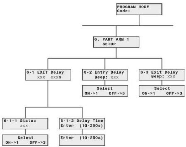
flowchart
graph TD
    A["PROGRAM MODE Code:"] --> B["6. PART ARM 1 SETUP"]
    B --> C["6-1 EXIT Delay XXXs"]
    B --> D["6-2 Entry Delay Beep: XXX"]
    B --> E["6-3 Exit Delay Beep: XXX"]
    C --> F["Select ON->1 OFF->3"]
    D --> G["Select ON->1 OFF->3"]
    F --> H["6-1-1 Status XXX"]
    G --> I["6-1-2 Delay Time Enter (10-250s)"]
    H --> J["Select ON->1 OFF->3"]
    I --> K["Enter (10-250s)"]
Scroll through the programming menu until '6. PART ARM 1 SETUP' is displayed and press ENTER .
Note: After configuring Full Arm press ESC to return to the top level programming menu.
EXIT-DELAY PERIOD
Scroll through the menu until '6-1 EXIT-DELAY' (and the current setting) is displayed.
Tochange the settings press ENTER.
On/Off Status
Default setting: ON
Scroll through the menu until '6-1-1 Status' (and the current setting) is displayed.
Tochange the setting press ENTER.
Press 1 to enable the exit-delay, or
Press 3 to disable the exit-delay.
Delay Period
Default setting: 30s
Scroll through the menu until '6-1-2 Delay Time' (and the current setting) is displayed.
Tochange the settings press ENTER.
Enter the required delay period (10 to 250s).
Press ENTER to save and exit, or
Press ESC to exit without saving.
Press ESC to return to top level Part-Arm 1 Setup menu.
EXIT-DELAY BEEPS
Allows the entry-delay warning beeps when activating Part-Arm 1 to be switched ON or OFF.
Default Setting: ON
Scroll through the menu until '6-2 Entry Delay Beep' (and the current setting) is displayed.
Tochange the setting press ENTER.
Press ENTER to enable the beeps, or
Press ESC to disable the beeps.
EXIT-DELAY BEEPS
Allows the exit-delay warning beeps when activating Part-Arm 1 to be switched ON or OFF.
Default Setting: ON
Scroll through the menu until '6-3 Exit Delay Beep' (and the current setting) is displayed.
Tochange the setting press ENTER.
Press 1 to enable the beeps, or Press 3 to disable the beeps.
PART-ARM 2 SETUP
The parameters in this menu control the systems exit-delay period and the exit/entry delay warning beeps during Part-Arm 2 mode.

flowchart
graph TD
    A["PROGRAM MODE Code:"] --> B["7. PART ARM 2 SETUP"]
    B --> C["7-1 EXIT Delay xxx xxxs"]
    B --> D["7-2 Entry Delay Beep: xxx"]
    B --> E["7-3 Exit Delay Beep: xxx"]
    C --> F["7-1-1 Status xxx"]
    D --> G["Select ON->1 OFF->3"]
    E --> H["Select ON->1 OFF->3"]
    F --> I["Select ON->1 OFF->3"]
    G --> J["7-1-2 Delay Time Enter (10-250s)"]
    H --> K["Enter (10-250s)"]
Scroll through the programming menu until '7. PART ARM 2 SETUP' is displayed and press ENTER .
Note: After configuring Full Arm press ESC to return to the top level programming menu.
EXIT-DELAY PERIOD
Scroll through the menu until '7-1 EXIT-DELAY' (and the current setting) is displayed.
Tochange the settings press ENTER.
On/Off Status
Default setting: ON
Scroll through the menu until '7-1-1 Status' (and the current setting) is displayed.
Tochange the setting press ENTER.
Press 1 to enable the exit-delay, or
Press 3 to disable the exit-delay.
Delay Period
Default setting: 30s
Scroll through the menu until '7-1-2 Delay Time' (and the current setting) is displayed.
Tochange the settings press ENTER.
Enter the required delay period (10 to 250s).
Press ENTER to save and exit, or Press ESC to exit without saving.
Press ESC to return to top level Part-Arm 2 Setup menu
ENTRY-DELAY BEEPS
Allows the entry-delay warning beeps when activating Part-Arm 2 to be switched ON or OFF.
Default Setting: ON
Scroll through the menu until '7-2 Entry Delay Beep' (and the current setting) is displayed.
Tochange the setting press ENTER
Press 1 to enable the beeps, or Press 3 to disable the beeps.
EXIT-DELAY BEEPS
Allows the exit-delay warning beeps when activating Part-Arm 2 to be switched ON or OFF.
Default Setting: ON
Scroll through the menu until '7-3 Exit Delay Beep' (and the current setting) is displayed.
Tochange the setting press ENTER.
Press 1 to enable the beeps, or Press 3 to disable the beeps.
TIME & DATE SETUP
The parameters in this menu allow the systems clock and calendar (required for the event log) to be configured.
Note: The clock will require updating to reflect any time changes due spring/autumn daylight saving.

flowchart
graph TD
    A["PROGRAM MODE Code:"] --> B["8. TIME & DATE SETUP"]
    B --> C["8-1 Date DD/MM/YY DDD"]
    B --> D["8-2 Time HH/MM/SS"]
    C --> E["DD/MM/YY"]
    D --> F["HH/MM/SS"]
Scroll through the menu until '8 TIME & DATE SETUP' is displayed and press ENTER.
Note: After configuring the Time and Date press to return to the top level programming menu.
DATE
Scroll through the menu until '8-1 Date' (and the current setting) is displayed.
Tochange the setting press ENTER.
Enter the correct date in the format 'dd/mm/yy'
Press ENTER to save and exit, or
Press ESC to exit without saving.
TIME
Scroll through the menu until '8-2 Time' (and the current setting) is displayed.
Tochange the setting press ENTER.
Enter the correct date in the format 'dd/mm/yy'.
Press ENTER to save and exit, or
Press ESC to exit without saving.
LATCH KEY SETUP
The parameters in this menu configures which Users the Latch-Key feature operates with and the telephone numbers that the system dials when the Latch-Key is activated.
Note: For the Latch-Key to operate correctly the telephone "Dial Method" (see system setup) and
the User "Latch-Key Message", (see User Setup) must be correctly set and programmed.
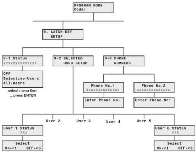
flowchart
graph TD
    A["PROGRAM MODE Code:"] --> B["9. LATCH KEY SETUP"]
    B --> C["9-1 Status xxxxxxxxxxxx"]
    B --> D["9-2 SELECTED USER SETUP"]
    B --> E["9-3 PHONE NUMBERS"]
    C --> F["OFF Selective-Users All-Users select menu item ...press ENTER"]
    D --> G["Phone No.1 xxxxxxxxxxxx"]
    D --> H["Phone No.2 xxxxxxxxxxxx"]
    E --> I["Phone No: Enter Phone No:"]
    E --> J["Phone No: Enter Phone No:"]
    G --> K["User 2"]
    G --> L["User 3"]
    G --> M["User 4"]
    G --> N["User 5"]
    J --> O["User 6 Status xxx"]
    K --> P["Select ON->1 OFF->3"]
    L --> Q["Select ON->1 OFF->3"]
Scroll through the top level programming menu until '9. LATCH KEY SETUP' is displayed and press ENTER.
Note: After completing the Latch Key Setup press to return to the top level programming menu.
STATUS
This controls which Users the Latch Key facility will operate with. If set to 'Selected-Users' the Latch Key will only operate with those users enabled in section '9-2 Selected User Setup'.
Default Setting: OFF
Scroll through the menu until '9-1 Status' (and the current setting) is displayed.
Tochange the setting press ← ENTER .
Scroll through the menu options until the required setting is displayed.
Press ENTER to save and exit, or
Press ESC to exit without saving.
SELECTED-USERS SETUP
This configures the individual users that the Latch-Key operates with when set to 'Selected-Users'.
Default Setting: OFF
Scroll through the menu until '9-2 SELECTED USER SETUP' is displayed and press ENTER.
Scroll through the menu until the required 'User Status' (and the current setting) is displayed.
To change the setting press ENTER .
Press 1 to enable the User in Latch-Key, or Press 3 to disable the User in Latch-Key.
After configuring all Users as required press ESC to return to the top Level Latch Key Setup menu.
TELEPHONE NUMBERS
Scroll through the menu until '9-3 PHONE NUMBERS' is displayed and press ENTER.
Scroll through the menu until the required 'Phone No._' (and the current setting) is displayed.
Tochange the number press ENTER.
Enter the new phone number (32 digits max).
Notes:
Press 📞 to insert a 3.5s pause in the dialling sequence.
Press to move the cursor left.
Press | to move the cursor right.
Press 📄 to delete the number under the cursor.
Press (and hold) to erase the entire number.
Press ENTER to save and exit, or
Press ESC to exit without saving.
After programming all required phone numbers press to return to the top level Voice Dialler menu.
ANSWER PHONE SETUP
The parameters in this menu allow the systems Answer-Phone facility to be configured and the greeting message to be recorded.
Note: For the Latch-Key to operate correctly the telephone "Dial Method" (see system setup) and the User "Latch-Key Message", (see User Setup) must be correctly set and programmed.
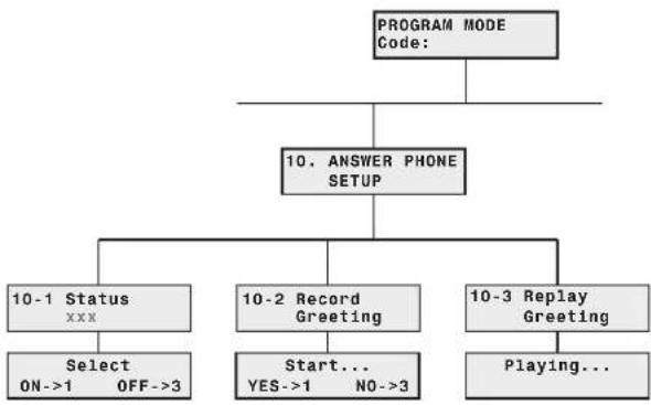
flowchart
graph TD
    A["PROGRAM MODE Code:"] --> B["10. ANSWER PHONE SETUP"]
    B --> C["10-1 Status XXX"]
    B --> D["10-2 Record Greeting"]
    B --> E["10-3 Replay Greeting"]
    C --> F["Select ON->1 OFF->3"]
    D --> G["Start... YES->1 NO->3"]
    E --> H["Playing..."]
Scroll through the programming menu until '10. ANSWER PHONE SETUP' is displayed and press ENTER.
Note: After completing the Answer Phone Setup press to return to the top level programming menu.
ANSWER-PHONE ON/OFF STATUS
Default Setting: OFF
Scroll through the menu until '10-1 Status' (and the current setting) is displayed.
Tochange the setting press ENTER.
Press 1 to enable the Answer-Phone, or Press 3 to disable the Answer-Phone.
Scroll through the menu until '10-2 Record Greeting' is displayed.
Torecord a new greeting message press ENTER.
Press 1 to start the voice recorder, (max duration: 12s).
When recording, press ESC to stop the recorder and cancel any remaining recording time. The new message will then be replayed.
Press 3 to disable the Answer-Phone.
REPLAY ANSWER-PHONE GREETING
Scroll through the menu until '10-3 Replay Greeting' is displayed.
To replay the recorded greeting message press ENTER
REMOTE MANAGER SETUP
The parameters in this menu configure the system telephone dialer to interface to the Alarm monitoring Service following the occurrence of a appropriate alarm or system event.
Note: For the Telephone dialler to operate correctly with the Alarm Monitoring Service the "Dial Method" and "Dialer Mode" (see system setup) must be correctly set and programmed.
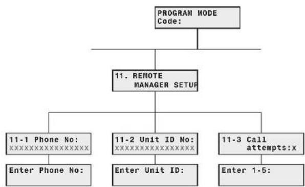
flowchart
graph TD
    A["PROGRAM MODE Code:"] --> B["11. REMOTE MANAGER SETUP"]
    B --> C["11-1 Phone No:XXXXXXXXXXXXXX"]
    B --> D["11-2 Unit ID No:XXXXXXXXXXXXXX"]
    B --> E["11-3 Call attempts:x"]
    C --> F["Enter Phone No:"]
    D --> G["Enter Unit ID:"]
    E --> H["Enter 1-5:"]
Scroll through the menu until '11. REMOTE MANAGER SETUP' is displayed and press ENTER.
Note: After completing the Remote Manager setup press ESC to return to the top level programming menu.
TELEPHONE NUMBER
Scroll through the menu until '11-1 Phone No:' (and the current setting) is displayed.
Tochange the number press ENTER.
Enter the new phone number (32 digits max).
Notes:
Press 📋 to insert a 3.5s pause in the dialling sequence.
Press | to move the cursor left.
Press ☐ to move the cursor right.
Press 📄 to delete the number under the cursor.
Press (and hold) to erase the entire number.
Press ENTER to save and exit, or
Press ESC to exit without saving.
UNIT ID
Scroll through the menu until '11-2 Unit ID No:' (and the current setting) is displayed.
Tochange the setting press ENTER.
Enter the 4 digit System ID Code obtained from the Alarm Monitoring Service provider. (This is not to be confused with the system house code or any User Access Codes).
Notes:
To enter code B, press

To enter code C, press

To enter code D, press

To enter code E, press

To enter code F, press

Press ENTER to save and exit, or
Press ESC to exit without saving.
CALL ATTEMPTS
This sets the maximum number of times that the dialler will attempt to contact the Alarm Monitoring Service.
Default setting: 3
Scroll through the menu until '11-3 Call Attempts' (and the current setting) is displayed.
Tochange the number press ENTER.
Enter the required number of dial attempts (1-5).
Press ENTER to save and exit, or
Press ESC to exit without saving.
OPERATING INSTRUCTIONS
When leaving the premises, the system must be Armed. However, before doing so, check that all windows are closed and locked, all protected doors are closed and PIR Movement Detectors are not obstructed. Ensure that pets are restricted to areas not protected by PIR Movement Detectors.
The system has three arming modes, ARM, Part-Arm 1 and Part-Arm 2. The Part-Arm modes allow for selected zones to be left in a Disarmed state whilst the remainder of the system is Armed.
When the system is Armed the mode being activated will be displayed on the screen followed by the status of the Latch Key feature. The programmed system exit-delay will be displayed and counted don on the screen. If exit-delay beeps are enabled the panel will beep with the beep rate increasing in steps as the exit-delay expires. At the end of the Exit period all active zones will be fully Armed. By this time the user must have left the property and closed the final protected door.
If while the system is armed a detector on an active zone is triggered the programmed entry-delay for that zone will be displayed and counted down on the screen. If entry-delay beeps are enabled the panel will beep with the beep rate increasing in steps as the entry-delay expires. If the system has not been Disarmed when the entry-delay expires a Full Alarm will occur. (Note: if the entry-delay for the zone triggering the alarm is disabled then an alarm will occur immediately the detector is triggered). Details of the zone event that triggered the alarm will be recorded in the Event-Log.
At the end of the programmed alarm duration the Siren and Control Panel alarms will stop and the system will automatically re-Arm itself, (subject to the conditions of the Zone Lockout feature.
Notes: - To conserve power and maximise battery life the PIR detector will only detect movement if there has been no movement detected within the previous 2 minutes.
- If the External Solar Siren is fitted and the 3 minute limit is enabled then the external siren will shut down when the programmed alarm duration expires or after 3 minutes, whichever occurs first.
Voice Dialler
If an alarm condition occurs and the Voice dialler is activated then the first enabled phone number in the dialling sequence will be called and the recorded alarm message will be replayed for the programmed "Play Time" period. The recipient should acknowledge the message by pressing the * button on their telephone keypad to shut down the dialler. If an acknowledgment signal is not received, then the next enabled number in the call sequence will be called. The dialler will continue calling each enabled number in turn until either all numbers in the sequence have been dialled the set number of times or the dialling sequence is cancelled by an acknowledged signal from a recipient.
Note: Unless the Dial Delay (see system setup menu) has been disabled there will be a 30s delay between an alarm occurring and the dialler activating.
ARMING THE SYSTEM
The system can be set in FULL ARM mode using either the Remote Control or the Control Panel as follows:
a) Press

on the Remote Control, or
b) Press


User Access Code
on the Control Panel.
PART ARMING THE SYSTEM: PART-ARM 1
The system can be set in PART-ARM 1 mode using either the Remote Control or the Control Panel as follows:
a) Press

on the Remote Control, or
b) Press


User Access Code
on the Control Panel.
PART ARMING THE SYSTEM: PART-ARM 2
The system can be set in PART-ARM 2 mode using either the Remote Control or the Control Panel as follows:
a) Press


on the Remote Control,
or
b) Press

on the Control Panel.
DISARM
The system can be Disarmed using either the Remote Control or the Control Panel as follows:
a) Press on the Remote Control, or
b) Press

on the Control Panel.
If when the system is disarmed the ‘ALARM MEM’ LED is flashing and the panel beeps every 10s, this indicates that an alarm condition has occurred. Inspect the Event Log to find out the type of the alarm and to assist in tracing the cause of the alarm or alternatively.
Press ESC to clear the LED and stop the beeping.
Note: If the system is Disarmed with the Remote Control the Siren will beep twice, (unless the warning beeps have been disabled on the Siren).
QUICK SET
The Quick Set function fully arms the system with a 5s exit delay:-

Alternatively, pressing D during the exit-delay period of any armed mode (including Part-Arm 1 and Part-Arm 2) will reset the remaining exit-delay period to 5s.
OMIT ZONE
To temporarily omit a zone and disable it during the next armed session:-

Scroll through the menu to select the required zone. The current zone setting will be displayed.
Tochange the setting press ENTER.
Press 1 to omit the zone, (i.e. zone omit = ON).
Press 3 re-enable the zone, (i.e. zone omit = OFF).
After configuring zones to be omitted as required press ESC to return to Standby mode.
Note: Omitting a zone will only affect the next armed session. When the system is disarmed the omitted zones will be re-enabled ready for the next armed session.
PERSONAL ATTACK (PA) ALARM
A full Alarm condition can be immediately initiated at any time (whether the system is Armed or Disarmed) in the event of threat or danger by activating a Personal Attack (PA) switch on either the Remote Control or the Control Panel as follows:
a) Slide the Personal Attack switch on the Remote Control upwards, or
b) Press and hold the 9! button for approximately 3 seconds on the Control Panel.
The alarm will continue either for the alarm duration when the system will automatically reset or until the system is disarmed.
TAMPER
If the battery cover of any device (except a Remote Control) is removed or if the Siren or Control Panel are removed from the wall then a Full Alarm condition will be initiated even if the system is Disarmed. The alarm condition will continue either for the alarm duration when the system will automatically reset or until the system is Disarmed. The 'ALARM MEM' LED on the Control Panel will flash and the panel will beep every few seconds to indicate an alarm has occurred.
Note: The Tamper protection facility on the Siren operates independently of the Control Panel. If the Tamper on the Siren is activated this will not be indicated at the Control Panel.
CHIME
The Chime facility can only be operated with the system in Standby mode.
Press 2 to toggle the Chime facility between ON and OFF.
EVENT-LOG
The Event Log will store the time, date and event type of the last 50 system events.
A new system event will be indicated by the 'ALARM MEM' LED flashing and the panel beeping every 10s. To cancel the LED and stop the beeping you must access the Event Log or press ESC.
Press 8? to access the Event Log, (from Standby Mode only):
The Event-Log will automatically display each event in turn starting with the most recent. The data for each event is shown on two screens with each screen being displayed for 5 seconds.
Use ↑ and ↓ to manually scroll through the events.
Press ESC to return to standby.
LEAVING A VOICE MEMO MESSAGE
To record a message at the Control Panel using the Voice Memo facility, proceed as follows:
Press ENTER to start recording.
Press ESC to stop the recorder and skip the remaining message time, (max message duration is 30s).
Note: The system can only store a maximum of 6 messages, (including answer-phone messages), if there is no spare message capacity then it will not be possible to record any message until one has been deleted.
Messages may be accessed or deleted either at the Control Panel (see Replay Messages) or via the "Remote Phone Access And Control" facility.
REPLAYING AND DELETING MESSAGES AT THE CONTROL PANEL
The presence of any unread memo or answer-phone messages is indicated o the Control Panel by the 'MESSAGE' LED being illuminated.
Messages may be accessed at the Control Panel as follows:
Press

Messages are replayed in the order they are received.
Press ESC during a message to skip to the end of the message.
At the end of each message there will the option of deleting the message just heard. To delete the message.
Press 1 to delete the message.
Press 1 to re-confirm and actually delete the message.
Note: Press 3 at either stage to cancel delete and move on to the next message.
After all messages have been replayed the system will automatically return to Standby Mode.
REMOTE PHONE ACCESS AND CONTROL
The Remote Phone Access and Control facility, if enabled, allows you to dial into the system and recover messages and to monitor/control the basic alarm system functions.
The control Panel will answer the call after the set number of rings and emit three beeps on the phone line.
Enter a User Access Code on the telephone keypad.
A valid User Access code will be acknowledged with one long beep.
An incorrect code will be acknowledged by two short beeps.
If a User Access Code is not entered within 30s or is entered incorrectly three times then the Control Panel will automatically hang-up the line.
Note: If the internal Answer-Phone is also enabled and there is space for a message then the call will be answered with the Answer-Phone greeting message. The User Access Code should be entered before the greeting message finishes, otherwise the answer-phone message recorder will be activated.
Double Dial-In for Operation with an External Answer-Phone:
If he Remote Access and Control feature is to be used and the system is operating in conjunction with an external Answer-Phone then
- The internal Answer-Phone will be disabled.
- Remote Phone Access and Control must be enabled.
- The number of ‘rings to answer’ for the Control Panel must be greater than that of the external answer-phone.
To access the Remote System Control facility the Control panel has a ‘double dial-in’ feature to enable the Control Panel to pick-up the phone call before the external Answer-Phone cuts in. The ‘double dial-in’ procedure operates as follows:
- D ial up the system and hang up after one or two rings.
- Wait a few seconds and then redial up the system within 20s, the system will pickup the phone after 1 ring.
- Enter the User Access Code as normal.
Remote Access and Control Functions:
The following functions may be access via the remote telephone. The system will acknowledge each signal with a single long beep.
Press 1 to initiate FULL ARM mode.
Press 2 to initiate Part-Arm 1 mode.
Press 3 to initiate Part-Arm 2 mode.
Press 4 to Disarm the system.
Press 5 to turn the Siren OFF.
Press 6 to turn the Siren ON.
Press 7 to to Listen-In via the Control Panel microphone.
Press # to stop Listen-In.
Note: Listen-In will be automatically cancelled after 5 minutes.
Press 8 to interrogate the alarm status. The
status will be indicated by the following tones which are repeated at 2s intervals for 15s.
One beep system Armed
Two beeps system Part-Armed
Three beeps Alarm triggered
One long beep system Disarmed
Press 9 to replay messages.
Press 0 to delete all messages.
Press # to end the session and Hang up the Control Panel line.
SIREN SERVICE MODE
In order to remove the Solar Siren from the wall to change the batteries. It is necessary to place the Siren into Service mode to prevent the Tamper protection switch on the Siren operating and triggering an alarm. When you have completed any alterations to the system remember to switch the siren back into Operating Mode.
The siren can be switched into service mode using either the Remote Control or Control Panel as follows:
Remote Control:
Press and hold the button on the remote control for approximately 6 seconds.
After approximately 6 seconds the Siren will produce a single long beep to indicate that it has switched into operating mode in a Disarmed state. The button should be released during or immediately after the long beep, otherwise the system will switch into an Armed state.
Control Panel:
With the system in Standby Mode with the Power LED ON.
Press

to enter Test mode, the Arm and Part-Arm LEDs will flash.
Press 5 to switch the Siren between Service Mode and normal Operating Mode. LED 5 will illuminatw to show that the appropriate signal is being transmitted.
After approximately 6 seconds the Siren will produce a single long beep to indicate that it has switched into operating mode in a Disarmed state.
Press ESC to return to Standby mode.
SIREN OPERATING MODE
The siren can be switched back into operating mode using either the Remote Control, Keypad or Control Panel as follows:
The siren can be switched into service mode using either the Remote Control or Control Panel as follows:
Remote Control:
Press and hold the 🔒 button on the remote control for approximately 6 seconds.
After approximately 6 seconds the Siren will produce a single long beep to indicate that it has switched into operating mode in a Disarmed state. The button should be released during or immediately after the long beep, otherwise the system will switch into an Armed state.
Control Panel:
With the system in Standby Mode with the Power LED ON.
Press

to enter Test mode, the Arm and Part-Arm LEDs will flash.
Press 5 to switch the Siren between Service Mode and normal Operating Mode. LED 5 will illuminate to show that the appropriate signal is being transmitted.
After approximately 6 seconds the Siren will produce a single long beep to indicate that it has switched into operating mode in a Disarmed state.
Press ESC to return to Standby mode.
BATTERY MONITORING
All system devices continuously monitor their battery condition. If the battery level of any device drops below acceptable levels then its low battery indication will be activated.
In addition if any PIR or Magnetic Contact detector has a low battery status it will be recorded by the Control Panel and a message stored in the Event Log.
When a low battery indicator is activated the device will continue to operate normally for up to 2 weeks (depending upon system use). However, the battery for that device should be replaced as soon as possible.
Note: Before removing the battery cover on any device to replace the battery ensure that the system is put into Test mode to avoid initiating a Full Alarm condition.
The low battery indication for each system component is as follows:
Control Panel:
During a period of mains supply interruption the Control Panel will be powered by the rechargeable backup batteries.
Under normal battery conditions the Power LED on the panel will flash at 1s intervals. However, under low battery conditions the Power LED will flash at 3s interval.
Remote Control:
When the Remote Control is operated under low-battery conditions the transmit LED will continue to flash after the button has been released.
Under normal battery conditions the LED will extinguish within 2s of the button being released.
PIR Movement Detector:
If the voltage level of any PIR battery falls below approx. 7.5V, the LED behind the detector lens will flash when movement is detected to indicate that the battery needs to be replaced.
Under normal battery conditions the LED does not illuminate unless the PIR detector is in Walk Test mode.
Magnetic Contact Detector:
Under low battery conditions, when the Detector is activated, the transmit LED will be illuminated for approximately 1s as the door/window is opened.
Under normal battery conditions the LED will not illuminate as the Detector is operated, (unless the Detector is in Test Mode with the battery cover removed).
MAINTENANCE
Your Alarm System requires very little maintenance. However, a few simple tasks will ensure its continued reliability and operation.
Important: Should you, for any reason, have to completely power-down the system (e.g. to move the system to a new premises) the Solar Siren must be switched into Service mode and the Control Panel must then be placed in Test mode before either device can be opened and the power disconnected before being removed from the wall. Ensure that the solar panel is covered with a light proof material to prevent it being energised.
SOLAR SIREN
- It is recommended that the Solar Panel on the top of the siren housing should be cleaned at least twice a year, preferably in the Spring and Autumn, using a soft damp cloth. Do not use abrasive, solvent based or aerosol cleaners. Do not attempt to clean inside the unit or allow water to enter the unit.
This will ensure that the Solar Panel does not become affected by the build up of excessive dirt and receives all the available light.
-
The Solar Siren should not be left for long periods with the batteries connected, unless the unit is able to receive sufficient light to maintain the battery charge. Failure to maintain charge to the unit will result in the rechargeable battery running unacceptably low. Should this occur, the unit must be recharged from a 7.5Vdc/100mA supply (e.g. from a mains adaptor power supply). When re-powering the Solar Siren fit a new 9V PP3 leak proof Alkaline power-up battery to ensure that the Unit receives sufficient power until the solar panel can recharge the main battery.
-
The main rechargeable battery has a typical life of 3-4 years and needs no maintenance during this period, provided the battery is kept charged. The battery will be damaged if it is stored in a discharged state for long periods.
Note: Before removing the Solar Siren from the wall in order to replace the batteries or for any other reason ensure that the Siren is first switched into Service Mode to prevent the Siren's Tamper switch operating and triggering an alarm, (see page 41).
Important: After changing the batteries and refitting in position, the Siren must be put back into normal Operating Mode, otherwise the siren will not sound in the event of an alarm condition
CONTROL PANEL
The rechargeable batteries have a typical life in excess of 3 to 4 years and need no maintenance during this period, provided they are kept charged. The batteries will be damaged if they are stored in a discharged state for long periods.
DETECTORS AND REMOTE CONTROL
The Detectors require very little maintenance. The batteries should be replaced once a year or when a low battery status is indicated.
BATTERIES
Note: Before removing the battery cover on any device to replace the battery ensure that the siren is switched into Service mode to avoid initiating a Full Alarm condition.
The specifications for replacement batteries are as follows:
Remote Controls: 1 x 3V CR2032 Lithium Cells (or equivalent)
Magnetic Contact 2 x 3V CR2032 Lithium Cells Detectors: (or equivalent)
PIR Movement 1 x 9V PP3 Alkaline Detectors:
Note: Where applicable only fit PP3 Alkaline type batteries. Rechargeable batteries should NOT be fitted.
At the end of their useful life the batteries should be disposed of via a suitable Recycling Centre. Do not dispose of with your normal household waste. DO NOT BURN.

The Rechargeable Batteries contain Sulphuric Acid - DO NOT ATTEMPT TO OPEN THE CASING.
ALARM RECORD
Complete the following information during installation for future reference when adding to your system and to assist Trouble Shooting.
| Zone Settings | |||||||||
| Zone | Detector Type(s) | Location Type | /Walk - | Final Exit Through | Entry Part Delay | Arm Part-Chime Arm | Arm | 1 | 2 |
| 1 | |||||||||
| 2 | |||||||||
| 3 | |||||||||
| 4 | |||||||||
| 5 | |||||||||
| 6 | |||||||||
| 7 | |||||||||
| 8 | |||||||||
| 9 | |||||||||
| 10 | |||||||||
You may make a note of your User Access Codes and Installer Access Code below.
System Access Codes
User 1: User 2: User 3: ____
User 4: User 5: User 6:
Master User: ____
System House Code
Use this diagram to record your House Code:
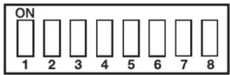
e.g.


Voice Dialler Phone Numbers
Phone No. 1: Phone_No.2:
Phone No. 3: Phone_No. 4:
Latch-Key Phone Numbers
Phone No. 1: Phone_No. 2:
Remote Security Manager Service
This information is confidential and should be kept in a safe location.
TROUBLE SHOOTING
| Symptom / Recommendation Symptom / Recommendation | |
| Control Unit not working - Power LED OFF or flashing1. Mains power failure - check if other electrical circuits are operable.2. Check that mains adaptor is plugged in and socket is switched ON.3. Check that DC jack plug from mains adaptor is connected in Control Panel.4. Check fuse/MCB in Consumer Unit on the circuit serving the Control Panel.Note: Before replacing any fuses or resetting the MCB, the cause of the failure should be investigated and rectified. | Detection Zone triggered (LED flashing) but no alarm is sounding1. Entry/Exit delay still running and not yet expired.2. Alarm duration period has already expired and system has reset.3. Alarm duration programmed to "no alarm". |
| Siren and Strobe operating but no alarm at Control Panel1. Siren Tamper switch activated. Check security of Siren fixing to wall and adjustment of anti-tamper switch to ensure switch is fully depressed.2. Siren Jamming detection circuit operated, (jamming detection at Control Panel disabled). | |
| Control Unit "Low Battery" LED flashing1. Check all PIR movement Detectors for low battery indication, (i.e. LED behind detection lens flashes when movement detected). Renew batteries as required. | Siren not responding to Control Panel1. Ensure 'House Code' is correctly set to the same code as all other system devices.2. Ensure main Siren configuration switch is set to SIREN.3. Incorrect User Access code being entered at Control Panel.4. Ensure Siren is within effective radio range of Control Panel and equipment is not mounted close to metal objects.5. Siren rechargeable battery discharged a. Clean Solar Panel.b. Check age of rechargeable battery – replace if at end of useful life.c. Fit new initial power-up battery and re-power up siren. |
| Control Unit "Low Battery" LED illuminated1. Check all Magnetic Contact Detectors for low battery indication, (i.e. LED on Detector body illuminates for 1s when detector triggered). | |
| Control Unit not accepting User Access code1. Pause between key depressions too long. Do not pause for more than 5 seconds between pressing keys.2. Incorrect code entered. Allow 5 seconds to elapse before re-entering correct code.3. Reset to factory defaults and reprogram system. | |
| Siren not responding to detector1. Detector battery low - Replace battery.2. Siren in Service Mode – switch back to operating mode using Remote Control or keypad.3. Ensure 'House Code' is correctly set to the same code as all other system devices.4. Ensure detector is within effective radio range of Siren and equipment is not mounted close to metal objects. | Full Alarm Condition occurs when system has not been triggered by an intruder or is disarmed1. Tamper switch activationa. check all detector battery covers to ensure correctly fitted.b. check Control Panel and Siren are securely mounted to the wall and tamper switch is closed.2. Personal Attack Alarm operated from a Remote Control or Control Panel.3. Jamming detection circuit operated. |
TROUBLE SHOOTING - continued
Symptom / Recommendation Symptom
/ Recommendation
LED on Remote Control not illuminating, or is dim when unit is operated
- Ensure battery is fitted with correct polarity.
- Ensure battery holder connections are making good contact with the battery.
- Battery flat - replace battery.
PIR Movement Detector false alarming
- Ensure that the detector is not pointing at a source of heat or a moving object.
- Ensure that the detector is not mounted above a radiator or heater.
- Ensure that the detector is not facing a window or in direct sunlight.
- Ensure that the detector is not in a draughty area.
- Pulse count set too low - reset to two pulse detection.
PIR Movement Detector not detecting a person's movement
- Ensure the battery clip is securely connected.
- Ensure 'House Code' is correctly set to the same code as all other system devices.
- Pulse count set too high - reset to one pulse detection.
- Ensure DIP switches 1, 2 and 3 of SW2 are correctly set, (i.e. 1=ON, 2=ON, and 3=OFF).
- Ensure that detector is mounted the correct way up, (i.e. with detection window at the bottom).
- Ensure that the detector is mounted at the correct height, (i.e. 2-2.5m).
- Allow up to three minutes for detector to stabilize and become fully operational. Leave the area for this period.
- Ensure detector is within effective radio range of the siren and is not mounted close to metal objects which may interfere with RF transmission.
PIR Movement Detector LED flashes on detection of movement, (device in normal operation mode)
- Ensure that the detector is configured for normal operation, (i.e. DIP switch 4 of SW2 is OFF).
- Low battery - replace battery.
Magnetic Contact Detector not working
- Ensure that magnet is correctly positioned in relation to detector and that the gap between magnet and detector is not too large.
- Ensure batteries are fitted with correct polarity.
- Ensure battery holder connections are making good contact with the batteries and PCB.
- Ensure 'House Code' is correctly set to the same code as all other system devices.
- Ensure DIP switches 9, 10 and 11 are correctly set, (i.e. 9=ON, 10=ON, and 11=OFF).
-
If there is no additional Magnetic Contact Detector connected ensure jumper link is fitted.
-
If an additional Magnetic Contact Detector is connected:
a. Ensure jumper link is removed.
b. Check that both contacts are closed.
c. Check that additional contact is correctly wired.
Note: If an additional contact is used then the doors/windows protected by both the main wirefree detector and the additional wired detector must be closed when either is opened. If one of the doors/windows is already open then the opening of the other door/window will not be detected.
- Ensure detector is within effective radio range of Control Panel and is not mounted close to metal objects which may interfere with RF transmission.
Magnetic Contact Detector false alarming
- Ensure that magnet is correctly positioned in relation to detector
- Ensure that gap between magnet and detector is less than 10mm.
- Tamper switch below battery cover not depressed - check battery cover is fitted correctly and that fixing lugs are not broken.
TROUBLE SHOOTING - continued
| Symptom / Recommendation Sym | / Recommendation |
| LED on Magnetic Contact Detector illuminating when door or window is openedLow battery - replace batteries. | Control Unit Not Contacting Remote Manager Service on AlarmTelephone line not connected or faulty - check phone line with another phone.Dial Method incorrectly programmed.Incorrect phone number for Remote Security Manager Service programmed.Incorrect system ID number for Remote Security Manager Service programmed.Remote Security Manager Service not commissioned or signed up. |
| Voice-Dialler Not Responding to AlarmTelephone line not connected or faulty - check phone line with another phoneDial Method incorrectly programmedIncorrect phone numbers programmedPhone numbers disabled in dialling sequenceAlarm messages not recorded. | |
| Answer-Phone not responding or recording messagesTelephone line not connected or faulty - check phone line with another phone.Dial Method incorrectly programmed.Answer-Phone disabledNo space in message store, 6 messages already recorded. | Remote Phone Access and Control facility not functioningTelephone line not connected or faulty - check phone line with another phoneRemote Access disabled.Incorrect User Access Code entered. |
| Cannot record Voice-Memo message at Control PanelNo space in message store, 6 messages already recorded. | Latch Key Not Responding when system DisarmedTelephone line not connected or faulty - check phone line with another phoneDial Method incorrectly programmedLatch-Key disabledLatch Key set to Selected-Users and not enabled for User that is Disarming the system.No Latch-Key phone numbers programmed. |
HELPLINE
If you have a problem with your alarm, please call the helpline on:
01268 563273
(Lines open 9.00am to 5.00pm, Monday to Friday)
EXTENDING YOUR ALARM SYSTEM
Your system may be extended to provide additional protection by adding additional PIR Movement Detectors, Magnetic Contact Sets and Remote Control Units.
ACCESSORIES
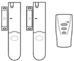 |  | 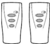 |
| SU1 - ACCESSORY SET2 x Magnetic Contact Detectors and 1 x Remote Control Unit. | SU2 - PIR MOVEMENT DETECTORS2 x PIR Movement Detectors. | SU3 - REMOTE CONTROL UNITS2 x Remote Control Units. |
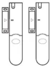 | 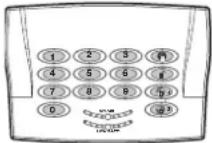 |  |
| SU4 - MAGNETIC CONTACT DETECTORS2 x Magnetic Contact Detectors. | SU5 - REMOTE KEYPAD1 x Remote Keypad. | SU6 - EXTERNAL SOLAR SIREN1 x External Solar Siren. |
GUARANTEE
Novar ED&S undertakes to replace or repair at its discretion goods (excluding non rechargeable batteries) should they become defective within 1 year solely as a result of faulty materials and workmanship.
Understandably if the product has not been installed, operated or maintained in accordance with the instructions, has not been used appropriately or if any attempt has been made to rectify, dismantle or alter the product in any way the guarantee will be invalidated.
The guarantee states Novar ED&S entire liability. It does not extend to cover consequential loss or damage or installation costs arising from the defective product. This guarantee does not in any way affect the statutory or other rights of a consumer and applies to products installed within the UK and Eire only.
If an item develops a fault, the product must be returned to the point of sale with:
- Proof of purchase.
- A full description of the fault.
- All relevant batteries (disconnected).
Friedland is a trade mark of Novar ED&S.
Friedland, Novar Electrical Devices and Systems.
The Arnold Centre, Paycocke Road, Basildon, Essex. SS14 3EA.
NOTES
Friedland
Novar Electrical Devices and Systems are Quality Assurance Registered to BS EN ISO9001:2000, by Asta
Keypad

• RF operating frequency: 433MHz
- Range: 50m max.
- Changeable 4 digit User Access code.
• Anti-Tamper protected
• Personal Attack (PA) facility
- Battery Life > 1 year
- Low Battery Indicator
RESEARCH & DEVELOPMENT
Our R & D Department is constantly developing new products.
We practice a policy of continued improvement and reserve the right to change specifications without prior notice.
If you have a problem with your Alarm, please call the Helpline on:
01268 563273
(Lines open 9.00am to 5.00pm, Monday to Friday).
CE
COMPONENT SPECIFICATION
External Solar Siren

• RF operating frequency: 433MHz
• Sealed lead acid battery 6V/1.2Ahr
• Solar Panel 7.5V - Charge Rate typically 60mA
- Operation time in complete darkness – up to 25 days
• 95dB Piezo Siren
• 3 minutes alarm duration limiter (optional)
- Siren Disable (selectable)
• Dual front and rear anti-tamper protection
- Jamming Detection
• Audible confirmation
Control Panel

• RF operating frequency: 433MHz
- Range: 50m max.
- Battery back-up
• Detector Low-Battery Status Indication
• RF Jamming Detection
• 90dB Piezo Siren
• Dual front and rear anti-tamper
- 6 Users + Master User
• 4 digit User Access Code
- 6 Wirefree Zones + 4 Wired zones
• 2 Part-Arm Facilities
• Independently programmable Entry and Exit delays.
- Entry/Exit Delay Warning (selectable)
• Programmable Alarm Duration
- Auto Reset
- Omit Zones
- Quick Set and Final Exit Set
- Walk Through Zones
- Zone lockout
- Chime
• Event Log (50 events)
• Digital Answer Phone & Voice-Memo
- Latch Key
- Remote Phone Access & System Control
- Listen-In facility.
• Front & Rear Anti-Tamper protection
• Personal Attack (PA) facility
• Telephone Voice Dialler
- Remote Security Manager interface
- Connections for Hardwired Siren
Remote Control

• RF operating frequency: 433MHz
- Range: 50m max.
• Personal Attack (PA) switch
- Operates all ARM, PART-ARM and DISARM functions
• Transmission indicator
- Battery life > 1 year
- Low battery indicator
Passive Infra-Red
Movement Detector

• RF operating frequency: 433MHz
- Range: 75m max.
• Detection range: up to 12m at 110°
- Walk test facility
- LOW/HIGH Detection Sensitivity
• Anti-Tamper protected
• Corner or surface mount
- Battery Life > 1 year
- Low Battery Indicator
Magnetic Contact
Detector

• RF operating frequency: 433MHz
- Range: 75m max.
- Test Mode
• Anti-Tamper protection
• Facility to add external wired Magnetic Contact Detector
- Battery Life >1 year
- Low Battery Indicator
Friedland, Novar Electrical Devices and Systems. The Arnold Centre, Paycocke Road, Basildon, Essex SS14 3EA. UK.



- Zone Communicating Wirefree Alarm System
- FOREWORD
- This manual should be retained in a safe place for future reference.
- IMPORTANT
- DECLARATION
- Tools and Equipment Required:
- SAFETY
- DEVICE RANGE
- Wall Type Range Reduction
- SYSTEM SECURITY
- CONTENTS
- KIT CONTENTS
- Also included:
- EXTENDING THE ALARM SYSTEM
- Component: Product Code
- INTRODUCTION AND OVERVIEW
- MULTIPLE USERS
- SYSTEM ARMING
- For example:
- ENTRY/EXIT DELAY
- ZONES
- ZONE LOCKOUT
- QUICK SET
- FINAL EXIT SET ZONE
- WALK THROUGH ZONE
- OMIT ZONE
- EVENT LOG
- CHIME
- VOICE DIALLER
- REMOTE MANAGER
- LATCH KEY
- ANSWER PHONE
- VOICE MEMO
- REMOTE PHONE ACCESS AND CONTROL
- TAMPER PROTECTION
- JAMMING DETECTION
- BATTERY MONITORING
- SYSTEM HOUSE CODE
- PLANNING AND EXTENDING YOUR WIREFREE ALARM SYSTEM
- TYPICAL INSTALLATION
- Typical Installation using only detectors supplied:
- Important:
- REMOTE CONTROL UNIT
- CONFIGURING THE REMOTE CONTROL
- CONTROL PANEL
- POSITIONING THE CONTROL PANEL
- INSTALLING THE CONTROL PANEL
- CONFIGURING THE CONTROL PANEL HOUSE CODE
- At the Control Panel:
- Using a Remote Control:
- TESTING THE CONTROL PANEL & REMOTE CONTROL
- PASSIVE INFRA RED (PIR) MOVEMENT DETECTORS
- POSITIONING THE PIR MOVEMENT DETECTORS
- INSTALLING AND CONFIGURING THE PIR MOVEMENT DETECTORS
- Ensure that the system is in Test mode (see page 20).
- TESTING THE PIR MOVEMENT DETECTORS
- MAGNETIC CONTACT DETECTORS
- POSITIONING THE MAGNETIC CONTACT DETECTORS
- INSTALLING AND CONFIGURING THE MAGNETIC CONTACT DETECTORS
- TESTING THE MAGNETIC CONTACT DETECTORS
- POSITIONING THE SOLAR SIREN
- INSTALLING AND CONFIGURING THE SOLAR SIREN
- TESTING THE SOLAR SIREN
- EXTERNAL CONNECTIONS
- TESTING THE SYSTEM
- INITIAL TESTING
- TESTING AN INSTALLED SYSTEM
- With the system in Standby Mode
- The system is now in the Test Mode
- WALK TEST
- ALARM TEST
- SOLAR SIREN SERVICE MODE SWITCHING
- VOICE DIALLER TEST
- REMOTE MANAGER TEST
- DEFAULT SETTINGS
- RESET FACTORY DEFAULT CONDITIONS
- PROGRAMMING INSTRUCTIONS
- Navigating through the Programming Mode Menus
- Telephone Application Setup
- Answer-Phone
- USER SETUP
- USERS 1-6
- User Access Code
- Record User Latch-Key Message
- Replay User Latch-Key Message
- MASTER USER
- SYSTEM SETUP
- At the Control Panel
- Using a Remote Control
- ALARM DURATION
- On/Off Status
- Siren Duration
- WREFREE SIREN
- ALARM RELAY
- RINGS TO ANSWER PHONE
- DIALLER DELAY
- DIAL METHOD
- DIAL MODE
- ZONE SETUP
- NAME
- TYPE
- Panic/PA
- Intruder
- Hour Intruder
- Fire
- Test
- FINAL EXIT SET
- ENTRY DELAY
- Delay Period
- PART-ARM 1
- PART-ARM 2
- WALK THROUGH
- VOICE DIALLER SETUP
- TELEPHONE NUMBERS
- Notes:
- ALARM MESSAGE PLAY TIME
- RECORD ALARM MESSAGES
- REPLAY ALARM MESSAGES
- CALL ROUTING
- TEL CONFIRM TIMES
- CALL ATTEMPTS
- FULL ARM SETUP
- EXIT-DELAY PERIOD
- ENTRY-DELAY BEEPS
- EXIT-DELAY BEEPS
- PART-ARM 1 SETUP
- PART-ARM 2 SETUP
- TIME & DATE SETUP
- DATE
- TIME
- LATCH KEY SETUP
- STATUS
- SELECTED-USERS SETUP
- ANSWER PHONE SETUP
- ANSWER-PHONE ON/OFF STATUS
- REPLAY ANSWER-PHONE GREETING
- REMOTE MANAGER SETUP
- TELEPHONE NUMBER
- UNIT ID
- OPERATING INSTRUCTIONS
- ARMING THE SYSTEM
- PART ARMING THE SYSTEM: PART-ARM 1
- PART ARMING THE SYSTEM: PART-ARM 2
- DISARM
- PERSONAL ATTACK (PA) ALARM
- TAMPER
- EVENT-LOG
- LEAVING A VOICE MEMO MESSAGE
- REPLAYING AND DELETING MESSAGES AT THE CONTROL PANEL
- Double Dial-In for Operation with an External Answer-Phone:
- Remote Access and Control Functions:
- SIREN SERVICE MODE
- Remote Control:
- Control Panel:
- SIREN OPERATING MODE
- PIR Movement Detector:
- Magnetic Contact Detector:
- MAINTENANCE
- SOLAR SIREN
- DETECTORS AND REMOTE CONTROL
- BATTERIES
- ALARM RECORD
- System Access Codes
- Voice Dialler Phone Numbers
- Latch-Key Phone Numbers
- Remote Security Manager Service
- TROUBLE SHOOTING
- TROUBLE SHOOTING - continued
- Symptom / Recommendation Symptom
- / Recommendation
- LED on Remote Control not illuminating, or is dim when unit is operated
- PIR Movement Detector false alarming
- PIR Movement Detector not detecting a person's movement
- PIR Movement Detector LED flashes on detection of movement, (device in normal operation mode)
- Magnetic Contact Detector not working
- Magnetic Contact Detector false alarming
- HELPLINE
- 563273
- EXTENDING YOUR ALARM SYSTEM
- GUARANTEE
- Friedland, Novar Electrical Devices and Systems.
- NOTES
- Friedland
- RESEARCH & DEVELOPMENT
- If you have a problem with your Alarm, please call the Helpline on:
- COMPONENT SPECIFICATION
Brand : FRIEDLAND
Model : SA5
Category : Surveillance Camera