
HDMI 91 IX - Range hood Ariston Thermo - Free user manual and instructions
Find the device manual for free HDMI 91 IX Ariston Thermo in PDF.
| Brand | Ariston Thermo |
| Model | HDMI 91 IX |
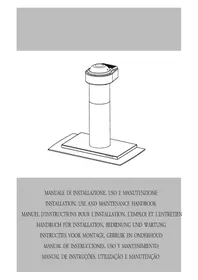
| Product type | Decorative island hood |
| Dimensions (W x H x D) | 89.8 x 94.8/124 x 70 cm |
| Exhaust duct diameter | 15 cm |
| Gross weight | 39 kg |
| Power supply | 230 V ~ 50 Hz |
| Total absorbed power | 260 W |
| Motor power | 180 W |
| Lighting | 4 halogen bulbs of 20 W each |
| Maximum airflow rate | 560 m³/h |
| Suction area | 944 cm² |
| Number of speeds | 3 + intensive (10 minutes) |
| Controls | Electronic buttons |
| Grease filters | Washable metal (dishwasher safe) |
| Charcoal filter | Optional, replace every 6 months |
| Installation types | Ducted or recirculating (recycling) |
| Minimum distance from cooking surface | 65 cm |
| Material | Stainless steel |
| Energy efficiency class | Not specified |
Frequently Asked Questions - HDMI 91 IX Ariston Thermo
User questions about HDMI 91 IX Ariston Thermo
0 question about this device. Answer the ones you know or ask your own.
Ask a new question about this device
Download the instructions for your Range hood in PDF format for free! Find your manual HDMI 91 IX - Ariston Thermo and take your electronic device back in hand. On this page are published all the documents necessary for the use of your device. HDMI 91 IX by Ariston Thermo.
USER MANUAL HDMI 91 IX Ariston Thermo
ARISTON FORMO ok 9-11-2006 10:58 Pagine 1

ARISTON
Indesit Company
Viale Aristide Merioni, 47
60044 Fabriano (AN) Italy
Tel. +39 0732 661
www.anstonchannel.com

natural_image
Woman and child preparing food together, one holding a spoon with strawberries, no visible text or symbols
ARISTON

Italiano, 1

English, 9

Deutsch, 17

Français, 25

Español, 33

Portoguês, 41

Nederlands, 49
HDMI 91 IX
Sommario
Installazione, 2-3
Montaggio
natural_image
3D mechanical part diagram with mounting holes and dimension lines (no text or symbols)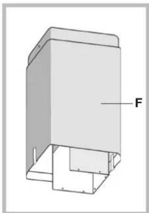
natural_image
3D diagram of a rectangular enclosure with labeled force vector F, showing internal structure and mounting base (no text or symbols beyond label)natural_image
Technical diagram of a mechanical assembly with a cylindrical component and a labeled component (no text or symbols present)natural_image
Diagram of a mechanical assembly with a bracket labeled M and a vertical rod inserted into a housing (no text or symbols present)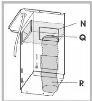
natural_image
Technical illustration of a mechanical assembly with a base plate and a cylindrical component labeled 'S' (no text or symbols beyond labels)natural_image
3D diagram of a layered structure with a labeled component 'P' and internal components, no readable text or symbols present.natural_image
Diagram of a mechanical or fluidic system with directional arrows indicating flow or movement (no text or symbols present)
Comandi

Tasto illuminazione
natural_image
Close-up of a wall-mounted electrical switch with two buttons and a dashed line indicating a measurement or adjustment (no text or symbols visible)natural_image
Technical diagram of a mechanical assembly with layered components and a labeled component 'P' (no text or symbols beyond label)natural_image
Simple line drawing of a magnifying glass over a circular object, with horizontal lines above (no text or symbols)Sicurezza generale
Technical information, 12
Electrical connection
Technical data
Description, 13
Filtering version
Ducting version
Operation, 14
Controls
Maintenance,15
Cleaning the hood
Cleaning the grease filters
Replacing the charcoal filter
Replacing the lamps
Precautions and tips, 16
General safety
Air vent
Disposal

ARISTON
Assembly
Before proceeding with the assembly operations, remove the grease filters so that the hood is easier to handle (for the instructions see the paragraph "Cleaning the grease filters" in the chapter on "Maintenance").
1) Using the special drilling template, drill the holes for fixing to the ceiling on the vertical side of your hob. Carefully observe all the indications for final positioning of the apparatus. Take into account that one of the template axes must correspond to the axis of the hood controls.
2) Fix the bracket (A) to the ceiling using the screws and screw anchors provided. Be careful, because the position of the bracket determines the final position of the apparatus: the side with the slot B corresponds to the side opposite the controls.
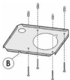
natural_image
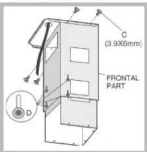
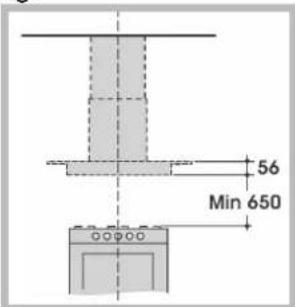
3D mechanical part diagram with mounting holes and a labeled section B (no text or symbols beyond label)3) Fix the telescopic structure to the bracket by means of 4 screws C (provided), running the air evacuation pipe through the telescopic structure and the electric power cable through the special hole in the bracket (the air evacuation pipe is not supplied). Set the height of the structure bearing in mind that the height of the hood is 56 mm and that the distance of the hood from the cooker must be at least 650 mm. Once the height is set, block the telescopic structure with 8 screws and 8 washers (D) – (2 screws and 2 washers on each side).
CAUTION: there is only 1 screw and 1 washer on the telescopic structure, take the other 7 from the accessories' bag.
4) Ducting version:
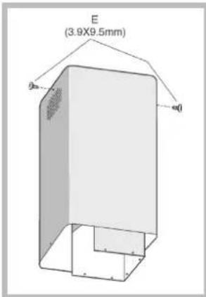
a) Take the upper flue (with the round slots) and fit it on the telescopic structure with the slots facing upwards; fit the flue to the bracket with 2 screws (E).
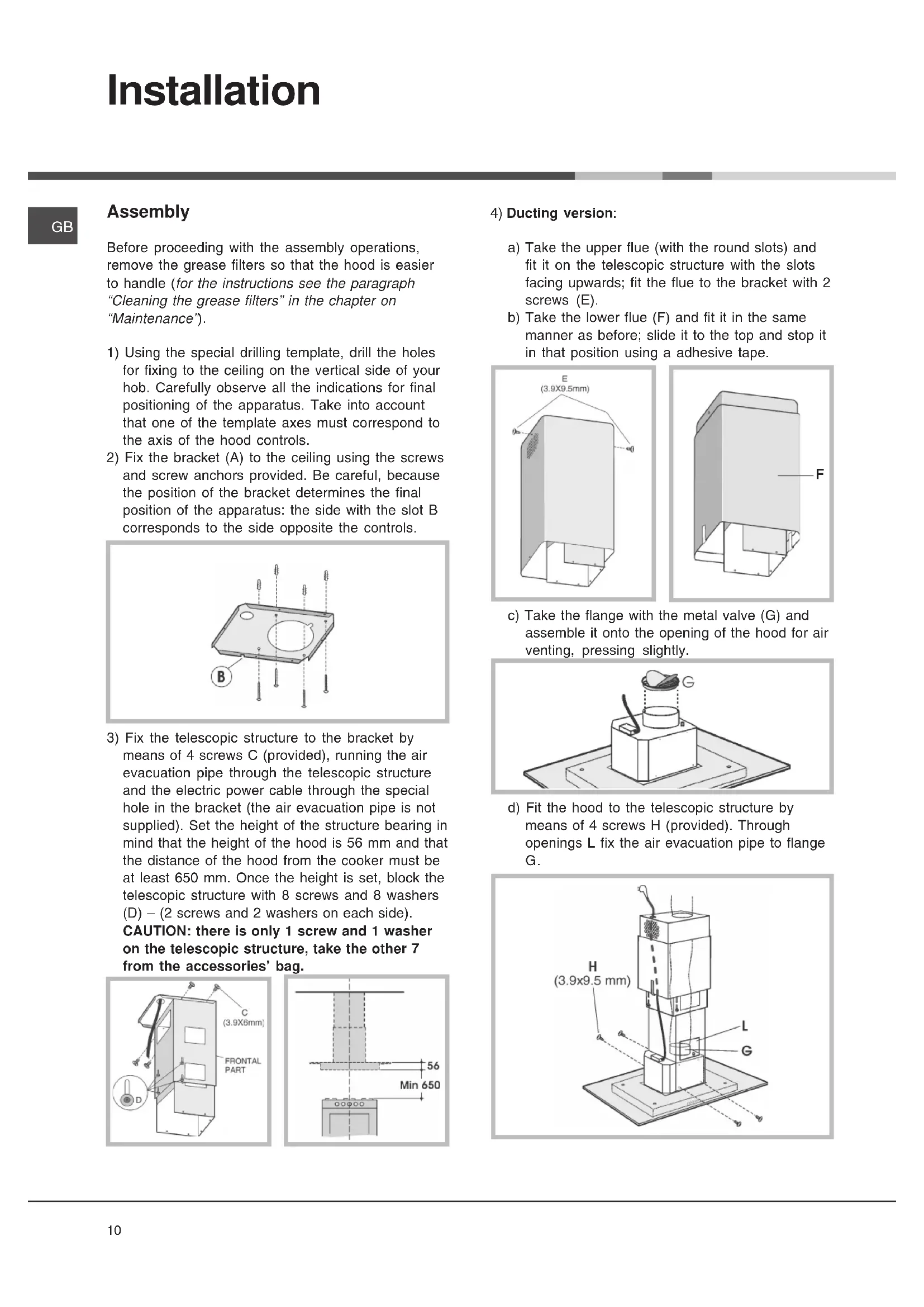
b) Take the lower flue (F) and fit it in the same manner as before; slide it to the top and stop it in that position using a adhesive tape.
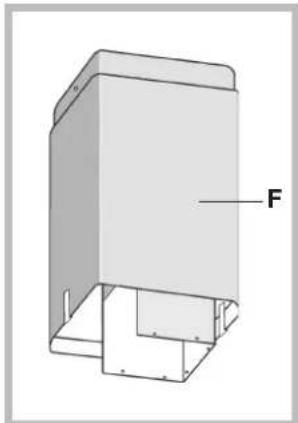
natural_image
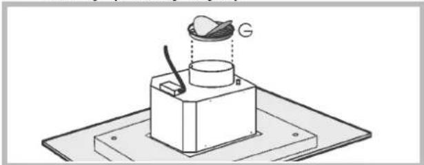
3D diagram of a rectangular enclosure with labeled force vector F, showing internal structure and mounting base (no text or symbols beyond label)c) Take the flange with the metal valve (G) and assemble it onto the opening of the hood for air venting, pressing slightly.
natural_image
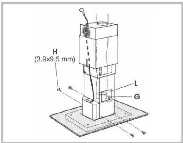
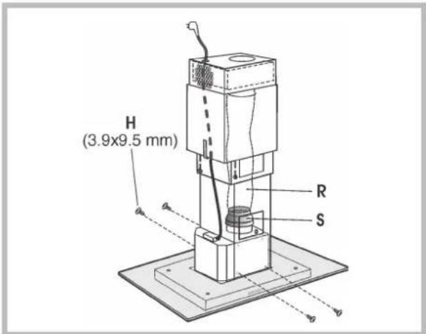
Technical line drawing of a mechanical assembly with a labeled component 'G' (no text or symbols beyond the label)d) Fit the hood to the telescopic structure by means of 4 screws H (provided). Through openings L fix the air evacuation pipe to flange G.
e) Make the electrical connection of the hood by means of the power cable (refer to the paragraph "Electrical connection").
f) Remove the adhesive tape and pull the lower flue downwards, placing it gently onto the apparatus.
g) Check if the charcoal filter P has already been installed; this filter is not necessary for the suction version, therefore it must be removed (see the instructions in the "Replacing the charcoal filter" chapter).
h) Installation is now complete and the grease filters can be reassembled.
5) Filtering version:
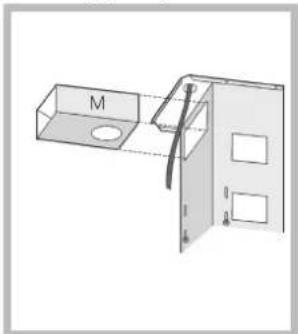
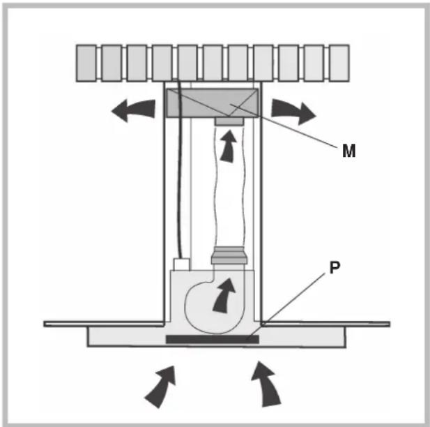
a) Insert the air baffle (M) in the structure.
b) Through the openings N, fit the flange (Q) to the baffle (M) locking it with a turning movement. Fix a flexible pipe (R) to the flange (Q) for air evacuation (the flexible pipe s not supplied).
natural_image
Technical line drawing of a mechanical assembly with labeled component M (no text or symbols beyond label)
c) Take the upper flue (with the round slots) and fit it on the telescopic structure with the slots facing upwards; fit the flue to the bracket with 2 screws (E) - figure on previous page.
d) Take the lower flue (F) and fit it in the same manner as before; slide it to the top and stop it in that position using a adhesive tape - figure on previous page.
e) Take the reduction (S) and assemble it onto the air venting opening of the hood, pressing slightly.
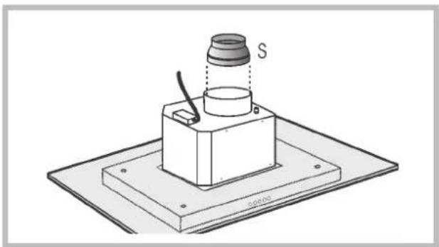
natural_image
Technical illustration of a mechanical assembly with a base plate and cylindrical component labeled 'S', no text or symbols present.f) Fit the hood to the telescopic structure by means of 4 screws H (provided).
g) Fix the air evacuation pipe (R) onto the reduction (S).
h) Make the electrical connection of the hood by means of the power cable (refer to the paragraph "Electrical connection").
i) Remove the adhesive tape and pull the lower flue downwards, placing it gently onto the apparatus.
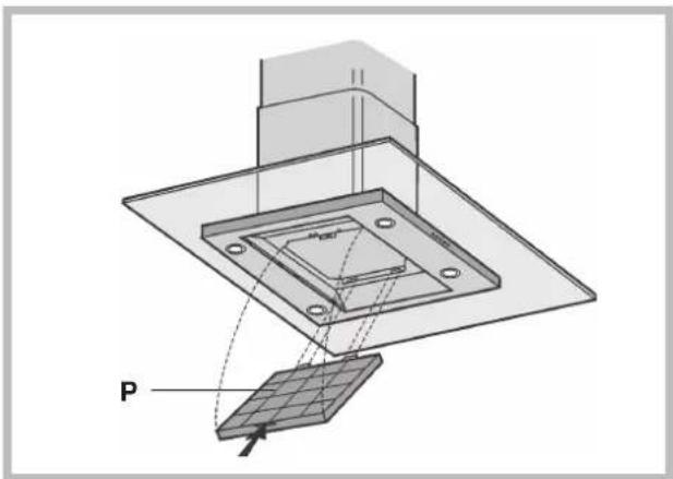
I) Check if the charcoal filter P has already been installed; this filter is necessary for the filtering version therefore it must be installed by inserting the 2 filter tabs into the relevant housing and turning in an upward direction.
natural_image
3D diagram of a layered electronic component with a labeled component 'P' and directional arrows, no readable text or symbols present.m) Installation is now complete and the grease filters can be reassembled.
Electrical connection
! Prepare the connection to the mains within the telescopic flue.
! When making the electrical connections, check that the voltage values correspond to those indicated on the data plate inside the appliance itself.
! In case your appliance is not furnished with a non separating flexible cable and has no plug, or has not got any other device ensuring omnipolar disconnection from the electricity main, with a contact opening distance of at least 3 mm, such separating device ensuring disconnection from the main must be included in the fixed installation.
! If your unit features a power lead and plug, position this so the plug is accessible.
! The following warning is valid in the United Kingdom only (in case your cable is not furnished with a plug). As the colours of the wires in the mains lead of this appliance may not correspond with the coloured markings identifying the terminals in your plug, proceed as follows: – the wire which is coloured blue must be connected to the terminal
Technical data
| Model HDMI 91 IX |
| Dimensions width 89.8 cmheight 94.8/124 cmdepth 70 cmOutlet pipe diameter 15 cm |
| Gross weight 39 Kg |
| Absorption Total 260 WMotor 1x180 WLamps 4x20 W |
| Flow rate 560 m ^3 /h |
| Grease filtersSuction surface area 944 cm ^2 |
which is marked with the letter N or coloured black; – the wire which is coloured brown must be connected to the terminal which is marked with the letter L or coloured red. For hoods in insulation class 2 (mod.HB60.2IX): – terminal of a three-pin plug.
- the wire which is coloured green and yellow must be connected to the terminal in the plug which is marked with the letter E or by the earth symbol [±] , or coloured green or green and yellow.
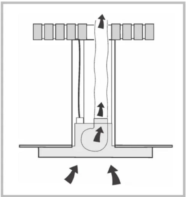
The hood may be in the filtering or ducting version. Decide from the outset which type is to be installed. For better efficiency, we recommend installing the hood in the ducting version (if possible).
Filtering version
The hood aspirates air from the kitchen impregnated with fumes and smells, purifies it through the grease filters and the charcoal filter, and then circulates clean air back into the room.
This version requires an air baffle (M) and a charcoal filter (P).
In order to maintain constant efficiency, the charcoal filter must periodically be replaced.
If the hood is not fitted with the charcoal filter, request one from the dealer.
Ducting version
The hood aspirates air from the kitchen impregnated with fumes and smells, passes it through the grease filters and then expels it to the outside through an exhaust duct.
For this version the charcoal filter does not need to be used.
natural_image
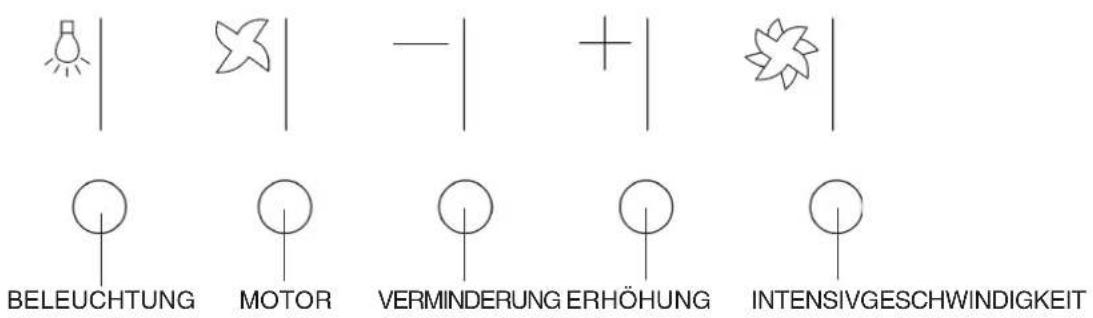
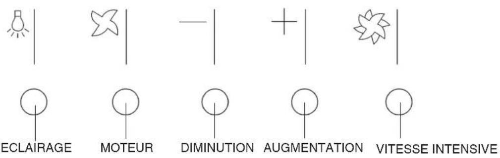
Diagram of a mechanical or fluidic system with directional arrows indicating flow or movement (no text or symbols present)Controls
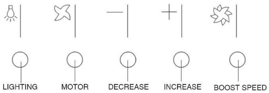

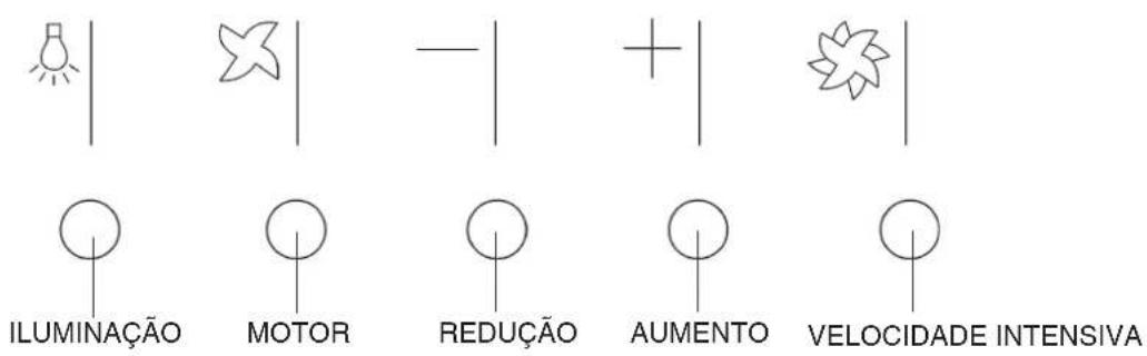
Light button
Turns the lights on/off.

Motor button
Activates/deactivates the motor. The motor is activated at the last speed set.
— Speed decrease button
Repeatedly pressing the button will reduce the motor speed until reaching the minimum speed.

Speed increase button
Repeatedly pressing the button will increase the motor speed until reaching the maximum speed.

Boost speed button
Activates the motor at boost speed for 10 minutes, after which the motor goes back to running at the speed set previously.
! Always switch off the electricity supply before carrying out any cleaning or servicing operations on the appliance.
! To avoid possible risks of fire always comply with the indicated instructions when cleaning grease filters and when removing grease deposits from the appliance.
Careful maintenance will assure good functioning and good efficiency over time.
Cleaning the hood
Any fat deposits should be removed from the appliance periodically depending on amount of use (at least every 2 months). Avoid using abrasive or corrosive products. To clean painted appliances on the outside, use a cloth dipped in lukewarm water and neutral detergent. To clean steel, copper or brass appliances on the outside, it is always best to use specific products, following the instructions on the products themselves. To clean the inside of the appliance, use a cloth (or brush) dipped in denatured ethyl alcohol.
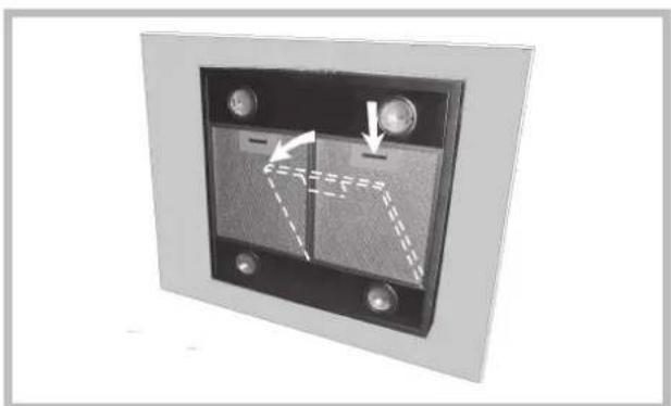
Cleaning the grease filters
To remove the grease filters, push the catch near the handle towards the inside and pull the filter downwards.
natural_image
Close-up of a black electronic device panel with two buttons and a dashed-line indicator line (no text or symbols)Wash the filters by hand or in the dishwasher using a neutral detergent. If they are washed in the dishwasher, any loss of colour will not jeopardise functioning of the filters in any way.
Clean the grease filters every 2 months on average depending on how heavily the hood is used.
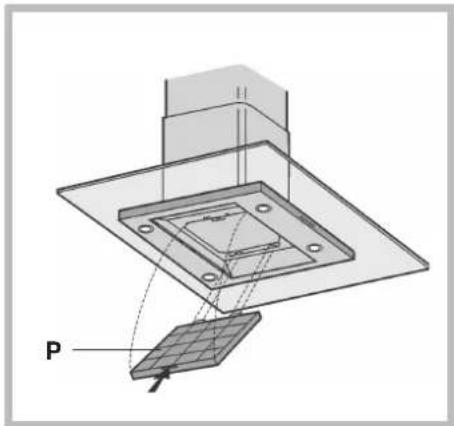
Replacing the charcoal filter
If using the hood in the filtering version, the charcoal filter (P) will periodically have to be replaced. First of all, remove the metal grease filters. Push the catch towards the inside and remove the charcoal filter from its seat.
natural_image
3D diagram of a layered structure with a labeled component 'P' and an arrow pointing to a component (no text or symbols beyond label)Replace the charcoal filter with one of the same type by carrying out the operations in reverse order.
Replace the charcoal filter on average every 6 months depending on how heavily the hood is used.
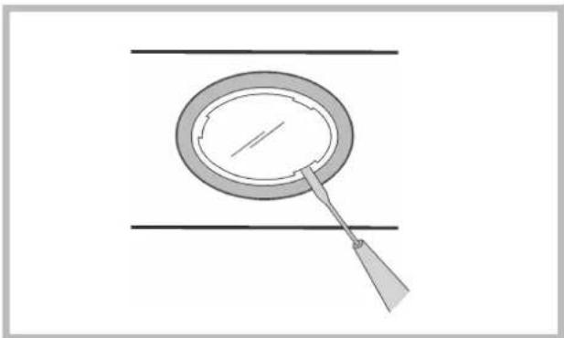
Replacing the lamps
Pay particular ATTENTION when carrying out this operation and remember to remove the voltage. To replace the halogen lamps, open the cover by prising in the slots. Replace with lamps of the same type.
WARNING: Do not touch the new lamp with bare hands.
natural_image
Simple line drawing of a magnifying glass over a circular object, with horizontal and diagonal lines (no text or symbols)General safety
! The distance between the supporting surface for the cooking vessels on the hob and the lower part of the hood must be at least 65 cm.
If the instructions for installation for the hob specify a greater distance, this has to be taken into account.
! ATTENTION: This appliance must be grounded.
When making the electrical connection, ensure that the power outlet is earthed.
When making the electrical connections, check that the current socket has a ground connection.
! Avoid using materials which could cause spurts of flame (flambées) near the appliance.
! When frying, take particular care to prevent oil and grease from catching fire. Already used oil is especially dangerous in this respect.
! Do not use uncovered electric grates.
! Do not place excessive weights above the hood.
Air vent
Should you install the ducting version, prepare the air vent hole and duct.
In the Ducting version, to get optimal conditions the air venting pipe should: be as short as possible, have the lowest number of bends (max bend angle: 90^ , be made of material approved by local authorities (according to the State), have its inner side as regular and smooth as possible. It is moreover recommended to avoid drastic changes of pipe cross section (recommended diameter: 150 mm).
! The air collected must not be conveyed into a duct used to blow off smokes from appliances fed with an energy other than electricity (central heating systems, thermosiphons, water-heaters, etc.).
! Comply with the official instructions provided by the competent authorities in merit when installing the disposal duct. In addition, exhaust air should not be discharged into a wall cavity, unless the cavity is designed for that purpose.
! The room must be well aerated in case a hood and some other heat equipment fed with an energy other than electricity (gas, oil, coal heaters, etc) operate at the same time. In fact the ducting hood, disposing of air, could create a vacuum in the room. The vacuum should not exceed 0,04mbar.
This prevents the gas exhausted by the heat source from being intaken again. It is therefore advisable to ensure the room contains air taps able to ensure a steady flow of fresh air.

Disposal
The European Directive 2002/96/EC on Waste Electrical and Electronic Equipment (WEEE), requires that old household electrical appliances must not be disposed of in the normal unsorted municipal waste stream.
Old appliances must be collected separately in order to optimise the recovery and recycling of the materials they contain and reduce the impact on human health and the environment.
The crossed out “wheeled bin” symbol on the product reminds you of your obligation, that when you dispose of the appliance it must be separately collected.
Consumers should contact their local authority or retailer for information concerning the correct disposal of their old appliance.

Italiano, 1

English, 9

Deutsch, 17

Français, 25

Español, 33

Portoguês, 41

Nederlands, 49
HDMI 91 IX
Zusammenfassung
Installation, 18-19
Montage
natural_image
3D diagram of a mechanical housing with screw holes and a labeled component (B), no text or symbols present.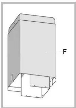
natural_image
3D technical drawing of a mechanical housing or enclosure with labeled component 'F' (no other text or symbols)natural_image
Technical diagram of a mechanical assembly with a base, tool, and top component (no text or symbols)natural_image
Technical line drawing of a mechanical assembly with labeled component M (no text or symbols beyond label)
natural_image
Technical diagram of a mechanical assembly with labeled component 'S' and base plate (no text or symbols beyond labels)natural_image
3D diagram of a layered electronic component with labeled point P and 'Pcc' annotation (no readable text or symbols beyond labels)natural_image
Diagram of a mechanical or fluidic system with directional arrows indicating flow or movement (no text or symbols present)D
Bedienung
natural_image
3D mechanical part diagram with labeled component B and bolt holes (no text or symbols beyond label)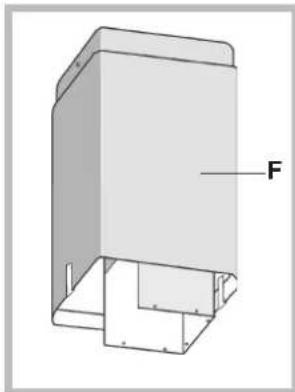
natural_image
3D diagram of a rectangular enclosure with internal components and labeled force vector F (no text or symbols beyond label)natural_image
3D diagram of a mechanical setup with a cylindrical component and a labeled part G, mounted on a base plate (no text or symbols beyond label)natural_image
Technical line drawing of a mechanical assembly with labeled component M (no text or symbols beyond label)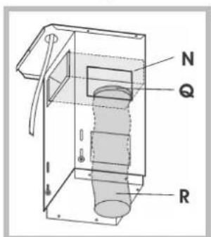
natural_image
Technical diagram of a mechanical assembly with a base plate and cylindrical component labeled 'S' (no text or symbols beyond label)natural_image
Technical diagram of a layered electronic component with a labeled component 'P' (no text or symbols beyond label)natural_image
Diagram of a mechanical or fluidic system with directional arrows indicating flow or movement (no text or symbols present)Commandes

Touche éclairage
natural_image
Diagram of a mechanical or electrical component with arrows indicating motion, no visible text or symbolsnatural_image
Technical diagram of a mechanical assembly with layered components and labeled component P (no text or symbols beyond labels)natural_image
Simple line drawing of a magnifying glass over a circular object, with horizontal lines above (no text or symbols)Sécurité générale
natural_image
3D diagram of a mechanical housing with mounting holes and a labeled component (B), no text or symbols present.natural_image
3D diagram of a rectangular enclosure with internal components and labeled force vector F (no text or symbols beyond label)natural_image
Technical illustration of a mechanical assembly with a base, cylindrical component, and labeled part G (no text or symbols beyond label)natural_image
Diagram of a door assembly with labeled component M, showing internal structure and mounting holes (no text or symbols beyond label)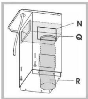
natural_image
Technical diagram of a mechanical assembly with a cylindrical component labeled 'S' and a tool inserted (no text or symbols beyond the label)natural_image
Technical diagram of a mechanical assembly with layered components and a labeled component 'P' (no text or symbols beyond label)natural_image
Diagram of a mechanical or fluidic system with directional arrows indicating flow or movement (no text or symbols present)Mandos

natural_image
Close-up of a mechanical or electrical component with dashed lines indicating internal movement, no visible text or symbols.natural_image
Technical diagram of a layered mechanical assembly with labeled component P (no text or symbols beyond label)natural_image
Simple line drawing of a magnifying glass over a circular object, with horizontal and diagonal lines above (no text or symbols)Seguridad general
natural_image
3D diagram of a rectangular enclosure with labeled force vector F, showing internal structure and mounting base (no text or symbols beyond label)natural_image
Technical illustration of a mechanical assembly with a base, tool, and top component (no text or symbols)natural_image
Technical diagram of a mechanical assembly with labeled part M and internal components (no text or symbols beyond labels)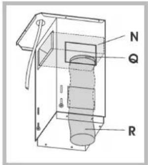
natural_image
Technical diagram of a mechanical assembly with a base, cylindrical component, and labeled section S (no text or symbols beyond label)natural_image
Technical diagram of a layered electronic component with a labeled component 'P' (no text or symbols beyond label)natural_image
Diagram of a mechanical or fluidic device with directional arrows indicating flow or movement (no text or symbols present)Comandos
Acende / Apaga as luzes.

Tecla do motor
natural_image
Close-up of a black rectangular panel with two buttons and a dashed-line arrow indicating rotation or movement (no text or symbols)natural_image
3D diagram of a layered electronic component with a labeled component 'P' and internal structure (no text or symbols beyond label)natural_image
Simple line drawing of a magnifying glass over a circular object, with horizontal lines above (no text or symbols)Segurança geral
natural_image
3D mechanical part diagram with labeled component B and mounting holes (no text or symbols beyond label)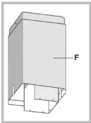
natural_image
3D diagram of a rectangular enclosure with labeled force vector F, showing internal structure and mounting brackets (no text or symbols beyond label)natural_image
Technical diagram of a mechanical assembly with a labeled component 'G' (no text or symbols beyond the label)natural_image
Diagram of a door with a handle and labeled component M, showing internal structure without any text or symbols.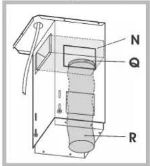
natural_image
Technical diagram of a mechanical assembly with a base, cylindrical component labeled 'S', and a workpiece (no text or symbols beyond the label)natural_image
Technical diagram of a layered electronic component with a labeled component 'P' (no text or symbols beyond label)m) Nu is de installatie voltooid en kunt u de antivetfilters weer monteren.
natural_image
Pure mechanical diagram showing a piston-cranked mechanism with directional arrows indicating motion (no text or symbols)Bedieningen
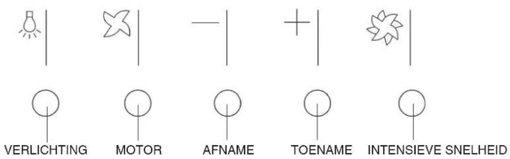

Verlichtingstoets
Schakelt de lampen in/uit.

Motortoets
Schakelt de motor in/uit.
natural_image
Diagram of a mechanical or electrical component with arrows indicating direction, no visible text or symbolsnatural_image
Technical diagram of a mechanical assembly with layered components and a labeled component 'P' (no text or symbols beyond label)natural_image
Simple line drawing of a magnifying glass over two parallel lines (no text or symbols)Algemene veiligheid


- ARISTON
- Sommario
- Comandi
- Tasto illuminazione
- Sicurezza generale
- Assembly
- 4) Ducting version:
- 5) Filtering version:
- Electrical connection
- Filtering version
- Ducting version
- Controls
- Light button
- Motor button
- — Speed decrease button
- Speed increase button
- Boost speed button
- Cleaning the hood
- Cleaning the grease filters
- Replacing the charcoal filter
- Replacing the lamps
- General safety
- Air vent
- Disposal
- Zusammenfassung
- Bedienung
- Commandes
- Touche éclairage
- Sécurité générale
- Mandos
- Seguridad general
- Comandos
- Tecla do motor
- Segurança geral
- Bedieningen
- Verlichtingstoets
- Motortoets
- Algemene veiligheid
Brand : Ariston Thermo
Model : HDMI 91 IX
Category : Range hood