
HDL 9 - Basket Ariston Thermo - Free user manual and instructions
Find the device manual for free HDL 9 Ariston Thermo in PDF.
| Product type | Extractor or recirculation hood |
| Brand | Ariston Thermo |
| Model | HDL 9 |
| Dimensions (W x D x H) | Approximately 90 cm (width) x 50 cm (depth) x 76 cm (height with chimney) (estimated) |
| Weight | Approximately 15 kg (estimated) |
| Power supply | 220-240 V ~ 50 Hz |
| Motor power | Not specified (estimated 200-300 W) |
| Lighting | 2 or 3 halogen spots of 20 W depending on model |
| Suction speeds | 3 speeds + intensive with programmed stop |
| Main functions | Extraction, recirculation, lighting |
| Evacuation type | External (extractor) or internal recirculation (filter) |
| Evacuation duct diameter | 120 or 150 mm |
| Filters | Metal grease filters (washable) and activated carbon filter (replaceable) |
| Maintenance | Clean metal filters every 2 months, replace carbon filter every 4 months |
| Exterior cleaning | Damp cloth and neutral detergent, no abrasive products or alcohol |
| Minimum safety distance to hob | 65 cm |
| Spare parts available | Metal filters, carbon filters, halogen bulbs |
| Recommended installation | By a specialist |
| Use | Domestic |
Frequently Asked Questions - HDL 9 Ariston Thermo
User questions about HDL 9 Ariston Thermo
0 question about this device. Answer the ones you know or ask your own.
Ask a new question about this device
Download the instructions for your Basket in PDF format for free! Find your manual HDL 9 - Ariston Thermo and take your electronic device back in hand. On this page are published all the documents necessary for the use of your device. HDL 9 by Ariston Thermo.
USER MANUAL HDL 9 Ariston Thermo
Safety warnings 13
Components 13
Installation instructions 14
Fitting the wall brackets and Splashback 14
Fixing the canopy 15
Electrical connection and working test 15
Ducting or Recirculation fitting 16
Fitting the telescopic chimney 17
OPERATION 18
Safety warnings 18
Instruction for Use 18
MAINTENANCE 19
Metal grease filters 19
Activated charcoal filter 19
Lighting 20
Cleaning 20
INSTALLATION 21
This canopy hood issdesigngrecedtoebefixedotanyngridenterialsurfaeeveergasgs or electric hotplate and cam be usedeither in the extraction mode (ducted to the outside) or in the recirculation mode (internal recycling).
Safety warnings
- Before commencing the installation, consideration should be given to the difficulties to be found during installation and to the bulky weight of the hood. The installation work must be undertaken by a qualified and competent person in conformity to the rules concerning the evacuation of contaminated air. The manufacturer disclaims all liability for any damage or injury caused as a result of not following the instructions for installation contained in the following text.
- When used in the extraction mode the cooker hood ducting must not be connected to a flue which is used for exhausting fumes from appliances supplied with energy other than electric such as a central heating flue or water heating flue.
- When installed, the hood must be positioned at least 65~cm above a cooking appliance.
- Never do flambe cooking under this cooker hood.
- Never leave frying pans unattended during use as overheated fats and oils may catch fire.
- If the room where the cooker hood is to be used contains a fuel burning appliance such as a central heating boiler then this must be of the room sealed or balanced flue type. If other types of flue or appliance are fitted ensure that there is an adequate supply of air into the room. When the cooker hood is used in conjunction with other appliances supplied with energy other than electric, the negative pressure in the room must not exceed 0,04 mbar to prevent fumes being drawn back into the room by the cooker hood.
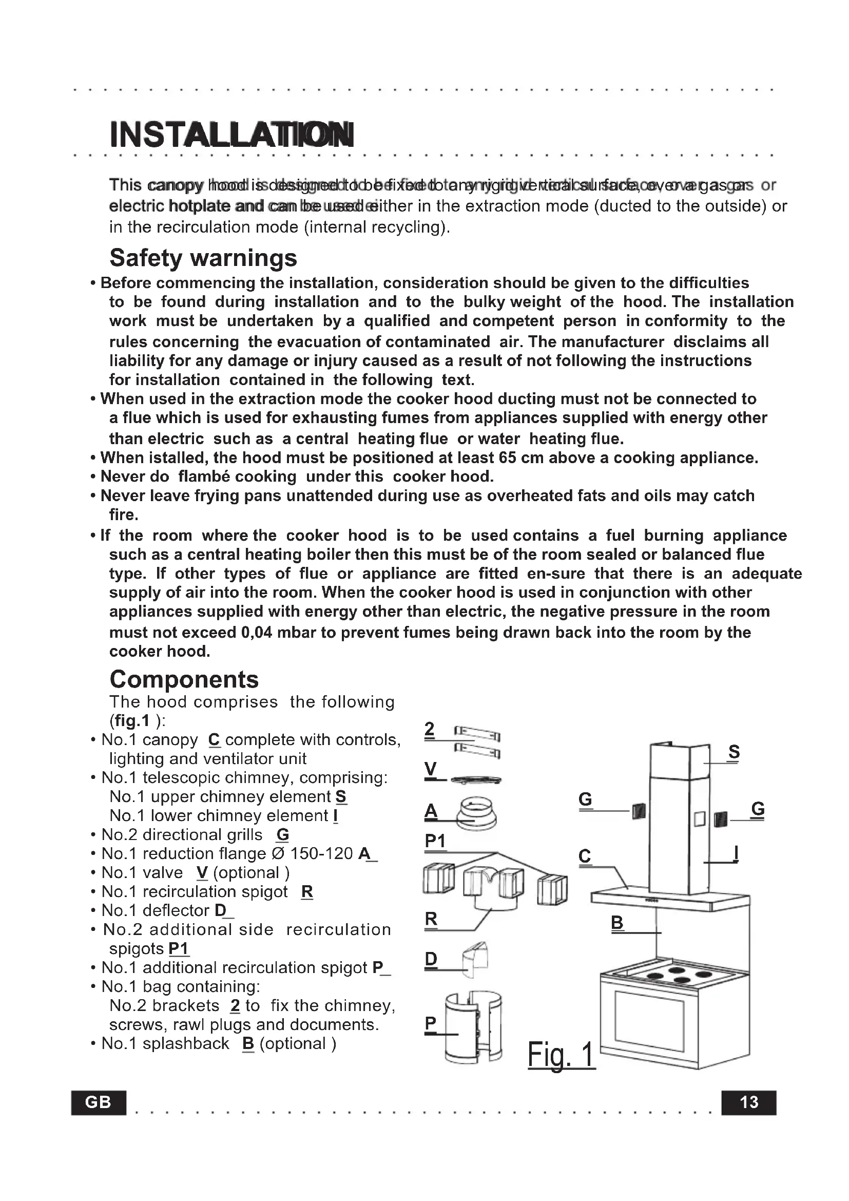
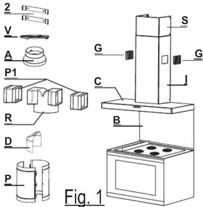
Components
The hood comprises the following (fig.1):
- No.1 canopy C complete with controls, lighting and ventilator unit
- No.1 telescopic chimney, comprising: No.1 upper chimney element S
No.1 lower chimney element I
No.2 directional grills G
No.1 reduction flange 0 150-120 A
No.1 valve V (optional)
No.1 recirculation spigot R
No.1 deflector D
No.2 additional side recirculation spigots P1
No.1 additional recirculation spigot P
No.1 bag containing: No.2 brackets 2 to fix the chimney, screws, rawl plugs and documents.
No.1 splashback B (optional)
Installation instructions
For easy installation, proceed as follows:
- FFixtheewathlbbaekets and Splashback
Fix the canopy - Electrical connection and working test
- Ducting or Recirculation fitting
Fix the telescopic chimney
Fitting the wall brackets and Splashback
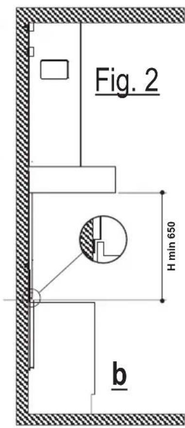
Please refer to (fig.2a-b):
Draw a vertical line on the wall, from the centre of the cooking appliance up to the ceiling, using a marking pen. This is to ensure the correct vertical alignment of the various parts.
Fixing the wall brackets item 2:
a) Place one of the brackets 2 against the wall approximately 1 or 2mm from the ceiling or from the top limit, aligning its centre (slot) with the vertical line.
b) Mark the centres of two keyholes in the bracket on the wall.
c) Rest the other bracket 2 against the wall, aligning it with the vertical line, at a distance X measured as
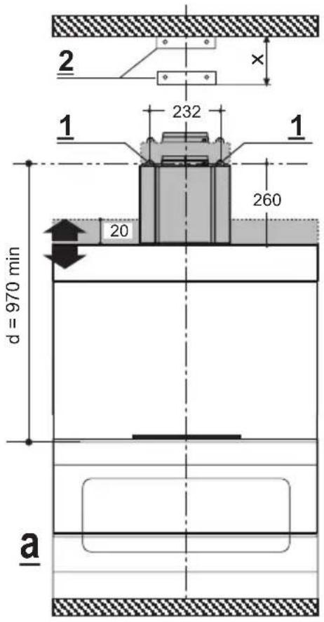
shown in fig. 2 equal to the height of the upper chimney element supplied with the hood. The position X may vary, according to the various sizes of upper chimney element available.
d) Mark the centres of the keyholes in the bracket on the wall.
- Drilling fixing holes item 1:
a) Mark a point on the vertical line at a distance from the cooking appliances of: d = 970 min (distance without splashback).
d = height of splashback + 320 mm (distance with splashback). The distance H is the minimum height in mm from the cooking appliances to the bottom edge of the front panel of the hood.
b) At the point marked, draw a horizontal line parallel to the cooking appliances.
c) Drill two holes in the wall 1 using an 8mm drill bit (fig.2a), and insert the rawl plugs and screws into the holes 1 (4.2× 44.4 screws). Fix the screws, leaving a space of 5 - 6mm
required to hook up the canopy. Small adjustments can be made using the color adjustment screws (see Fitting the canopy). The hood should have a maximum excursion of 20 mm.
- Splashback (optional)
When a splashback is to be fitted, the distance between the hood and the cooking appliances will be determined by the height of the splashbac and whether or not there is a raised back on the worktop. The splashback is to be installed before installing the canopy. If the splashback is to be fixed to the wall using both the top and bottom fixing holes, care must be taken to ensure that the splashback is fitted at the correct height before fixing the base units or at least the worktop covering them. As this is a complex operation, it should only be undertaken by the technician installing the kitchen units or by a competent person who knows the final dimensions of the units. If the splashback is to be fixed through the top fixing holes only, proceed as follows:
a) Rest the splashback on the worktop and against the wall, as illustrated in fig.2 .
b) Mark the centres of the two holes in the top surface.
c) Drill the wall using an 8 mm drill bit, and fix the splashback using the rawl plugs and screws provided.
d) If necessary, the installer should secure the splashback to the wall by tucking the bottom edge down behind the rear of the worktop.
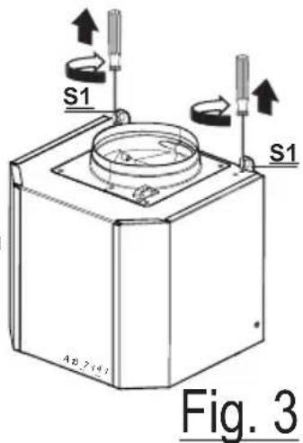
Fixing the canopy
Before starting to fix the canopy it will be necessary to adjust the support brackets S1 by turning the adjustment screws in a clockwise direction until their reach their limit (Fig.3):
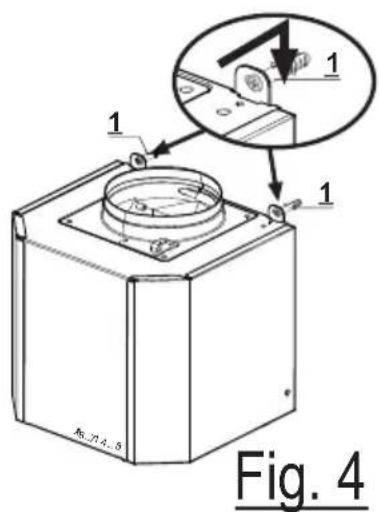
a) Hook the canopy onto the two size 4.2 × 44.4 screws 1_fitted as described above (Fig.4).
b) Level the hood by turning the adjustment screws and then locking them.
Electrical connection and working test
- Before connecting to the mains supply ensure that the mains voltage corresponds with the voltage on the rating plate inside the hood.
- Connect the cooker hood to the mains via a double pole switch which has 3mm clearance between the contacts.
The appliance must be earthed. - Once the electrical connection has been completed, check that worktop illumination, motor and speed work properly.
Ducting or Recirculation fitting
- Dutitiggifittigg
-
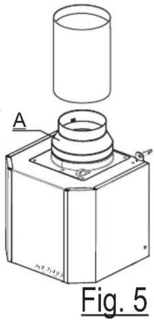
The body can be used to the outside using either rigid or flexible ducting 120 or 150~mm , the choice of which is left to the installer. When 120~mm ducting is to be used it will be necessary to install the reduction flange item A on the air outlet (fig.5).
-
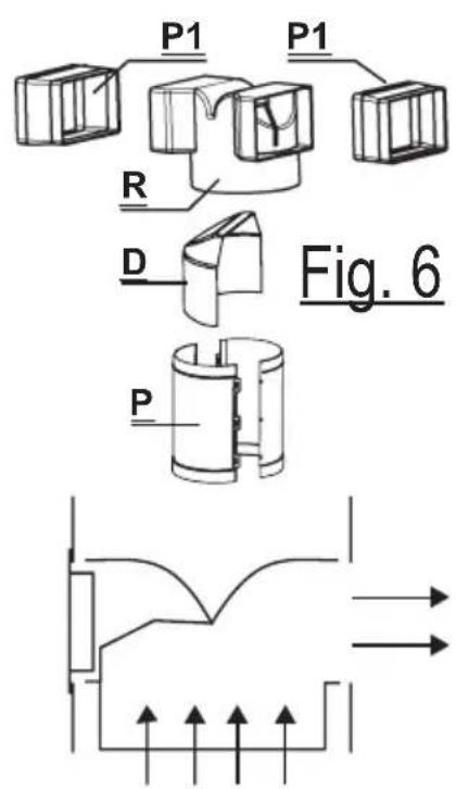
When ducting the hood through the side air outlet from the lower chimney element I it is necessary to insert deflector D into spigot R to close off the opening that is not being used (fig.6).
-
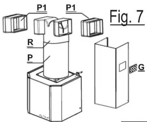
Cut the additional spigot P in correspondence with outlets 1 and 2, which must be formed directly on the piece. Connect the additional spigot P to the round fan outlet, pushing it downwards, and fit spigot R to additional spigot P in a similar manner (make sure that the two additional side recirculation spigots P1 are fitted to spigot R). Make sure that the height of the assembly R + P corresponds to the height of the chimney outlet (fig. 7).
-
If the hood is supplied with the activated charcoal filters fitted, the filters should be removed (see paragraph on Maintenance).
- Recirculation fitting
-
The filtered air is returned to the room through the two plastic side grills G on the lower chimney element I.
-
Connect the additional spigot to the round fan outlet, pushing it downwards, and fit spigot to additional spigot in a similar manner (make sure that the two additional side recirculation spigots are fitted to spigot ). Cut the additional spigot in correspondence with outlets 1 and 2, which must be formed directly on the piece. Make sure that the height of the assembly + corresponds to the height of the chimney outlet.(fig.7).
-
Fit the activated charcoal filters inside the canopy (see paragraph on Maintenance). Do not fit the venting grilles until after the chimney has been installed.
Fitting the telsaccopicchimney
- Toffttthe upper section S first expand the two side pieces slightly, hook them behind the brackets 2 and close them together again until they touch. Fix the upper section S to the brackets 2 using four of the screws provided in the bag of accessories (fig. 8).
- Fit the lower section I as above, between the upper section S and the canopy C using two of the screws provided in the bag of accessories.
- Chimney with venting grilles: Snap the venting grilles into position in the apertures located on the chimney section, so that the symbol is turned upwards and the symbol
faces forwards. Also, when the hood is used in recirculation mode, ensure that the grilles are properly secured to the inside of the recirculation spigot R (fig.9).
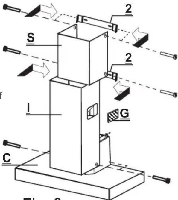
Fig. 8
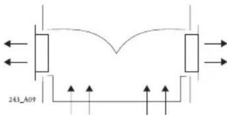
Fig. 9
OPERATION
Safety warnings
- BBefore eanirig goutanyankihchdf oainatienhamaeoc er ceaning indsienne teththe bdofothetheains supply.
- The grease filters and the charcoal filter should be cleaned or replaced as recommended by the manufacturer or more frequently if the hood is used consistently over 4 hours per day.
- When using a gas hob in connection with the cooker hood never leave the burners of the hob uncovered while the hood is in use or when the pans have been removed. Switch off the gas before removing the pan, or for just short periods and never leave the hob unattended.
- Always ensure that the flame is kept at the correct intensity to prevent the flame from licking round from the bottom of the pan; this will save energy and will avoid a dangerous concentration of heat.
- Always ensure that the appliance is used in accordance with the manufacturer's instructions for the removal of contaminated air and odours during cooking.
Instruction for Use
Control panel (fig.10)
The layout of the control panel is as follows:
Key 1 = Turns the lighting system on and off
Key T2 = Turns the motor on and off (LED T2 is turned on)
Key T3 = Decreases the working speed
Key T4 = Increases the working speed
Key T5 = Intensive speed with timed stoppage (LED T2 starts to flash). Suitable to deal with maximum vapour emission, this turns off automatically 10 minutes after starting operation. It can be disabled by pressing the key T5.
T1 T2 T3 T4 T5
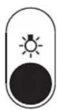
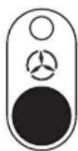
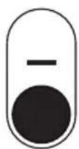

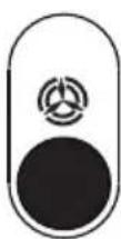
Fig. 10
MAINTENANCE
Constant maintenance guarantees proper operation and long-term reliability. Particular attention should be paid to the metal grease filters and, for recirculation hoods only, to the activated charcoal filters.
Metal grease filters
- Cleaning
The metal grease filter should be cleaned every two months with normal usage and can be cleaned in a dishwasher or by hand using a mild detergent or liquid soap.
- Removing the filters
Remove the filters one at a time, pushing the handle towards the rear of the hood (fig. 11). When replacing, ensure that the handle faces outwards.
WARNING: always comply with the maintenance and replacement times indicated, in order to avoid a possible risk of fire when the filters are saturated with grease.
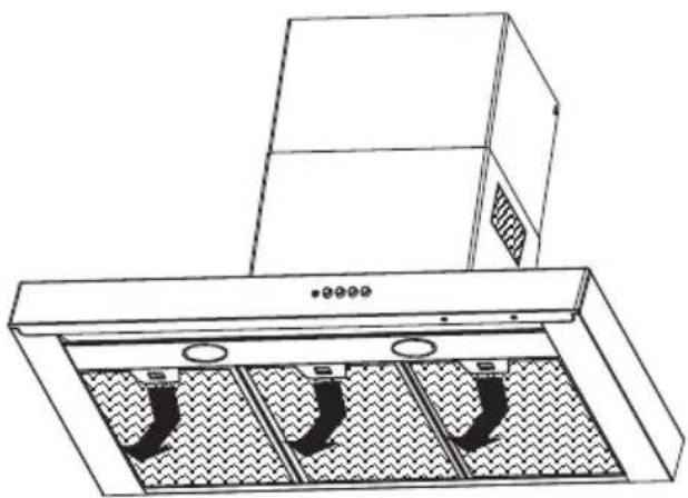
Fig. 11
Activated charcoal filter
Operation
Active carbon filters can withhold odours up to saturation. They cannot be washed or regenerated and must therefore be replaced every 4 months, or more frequently if intensely used.
- Replacing
Take off the metal grease filters (fig.11) and remove the activated charcoal filter from its housing by turning the clips provided (fig.12). Fit the new activated charcoal filter and replace the metal grease filters.
WARNING: always comply with the maintenance and replacement times indicated, in order to avoid a possible risk of fire when the filters are saturated with grease.
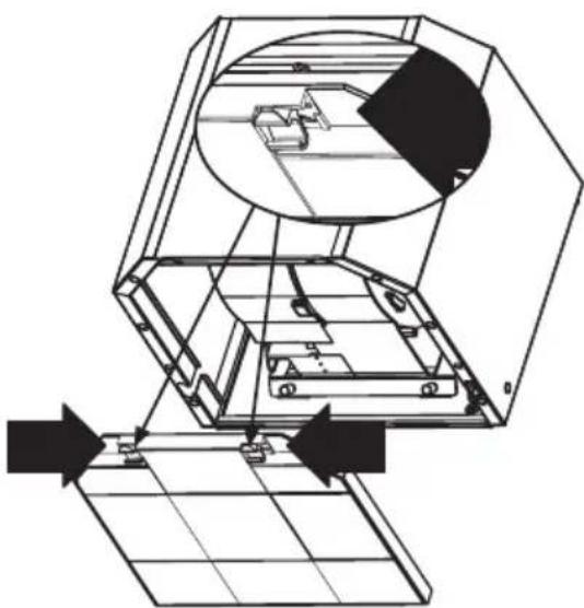
Fig. 12
Lighting
60 cm model, two 200Wh halogen spotlights.
90 and 1200 commodelithree20WW halogen spotlights.
To replace (fig.13)
Remove the two screws fixing the metal ring, extract the spotlight from the lamp holder by pulling gently. When replacing the spotlight, make sure that the two pins are correctly inserted in the housing on the lamp holder.
Cleaning
When cleaning the hood:
- Never use a wet cloth or sponge, or running water.
- Never use thinners or products containing alcohol, as they might damage the paintwork.
- Never use abrasive cleaning materials, in particular when cleaning stainless steel surfaces.
It is recommended to use a damp cloth and mild liquid household cleaner.
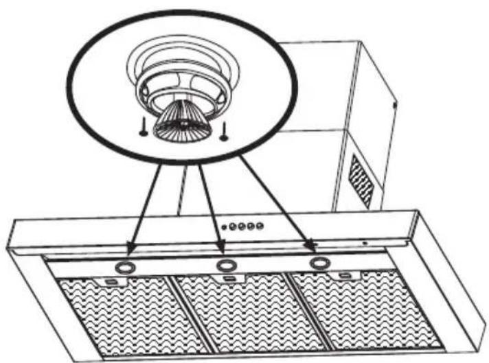
Fig. 13
INSTALLATION
Bedieningspaneel (afb.10)
Model van 60 cm. 2 halogeemspotijes van 20 W.
This appliance complies with European regulations on low voltages, EEC Directive 73/23 on electrical safety, and with the following European regulations: EEC Directive 89/336 on electromagnetic compatibility and EEC Directive 93/68 on EC marking.


- OPERATION 18
- MAINTENANCE 19
- INSTALLATION 21
- Safety warnings
- Components
- Installation instructions
- Fitting the wall brackets and Splashback
- Please refer to (fig.2a-b):
- Fixing the wall brackets item 2:
- - Drilling fixing holes item 1:
- - Splashback (optional)
- Fixing the canopy
- Electrical connection and working test
- Ducting or Recirculation fitting
- - Dutitiggifittigg
- - Recirculation fitting
- Fitting the telsaccopicchimney
- OPERATION
- Instruction for Use
- Control panel (fig.10)
- MAINTENANCE
- Metal grease filters
- - Cleaning
- - Removing the filters
- Activated charcoal filter
- - Replacing
- Lighting
- Cleaning
- INSTALLATION
- Bedieningspaneel (afb.10)
Brand : Ariston Thermo
Model : HDL 9
Category : Basket