
HDM 9 IX - Basket Ariston Thermo - Free user manual and instructions
Find the device manual for free HDM 9 IX Ariston Thermo in PDF.
| Product Type | Decorative wall hood, extraction or recirculation mode |
| Brand | Ariston Thermo |
| Model | HDM 9 IX |
| Width | 90 cm (estimated based on reference) |
| Depth | Approximately 50 cm (standard estimate) |
| Height (telescopic chimney) | Adjustable from approximately 65 to 110 cm |
| Weight | Approximately 18 kg (estimate) |
| Power supply | 220-240V / 50Hz, bipolar connection with 3 mm contact opening |
| Motor power | Not specified, 3 speeds |
| Lighting | 3 halogen bulbs 20 W each (type G4) |
| Grease filters | Metallic, dishwasher safe (every 2 months) |
| Activated charcoal filter | Optional for recirculation mode, replace every 4 months |
| Minimum safety distance | 65 cm above the cooking surface |
| Connection diameter | 120 or 150 mm depending on supplied flange |
| Functions | Lighting, 3 extraction speeds, touch or button |
| Installation | Wall-mounted, exhaust upward, through wall or sideways |
| Noise level | Not specified, quiet on first speed |
| Material | Stainless steel for body and chimney |
| Warranty | According to manufacturer's conditions (typically 2 years) |
| Manual available | Free PDF on notice-facile.com in multiple languages |
Frequently Asked Questions - HDM 9 IX Ariston Thermo
User questions about HDM 9 IX Ariston Thermo
0 question about this device. Answer the ones you know or ask your own.
Ask a new question about this device
Download the instructions for your Basket in PDF format for free! Find your manual HDM 9 IX - Ariston Thermo and take your electronic device back in hand. On this page are published all the documents necessary for the use of your device. HDM 9 IX by Ariston Thermo.
USER MANUAL HDM 9 IX Ariston Thermo
MANUALE DI INSTALLAZIONE, USO E MANUTENZIONE
INSTALLATION, USE AND MAINTENANCE HANDBOOK
MANUEL D'INSTRUCTIONS POUR L'INSTALLATION, L'EMPLOI ET L'ENTRETIEN
HANDBUCH FÜR INSTALLATION, BEDIENUNG UND WARTUNG
INSTRUCTIES VOOR MONTAGE, GEBRUIK EN ONDERHOUD
MANUAL DE INSTRUCCIONES, USO Y MANTENIMIENTO
MANUAL DE INSTRUÇOES, UTILIZAÇAO E MANUTENÇAO
Italiano . 3
English . 12
Francais . 21
Deutsch . 30
Nederlands . . . . . . . . . . . . . . . . . . . . . . . . . . . . . . . . . . . . . . . . . . . . . . . . . . . . . . . . .
Espanol . 48
Portugues . . . . . . . . . . . . . . . . . . . . . . . . . . . . . . . . . . . . . . . . . . . . . . . . . . . . .
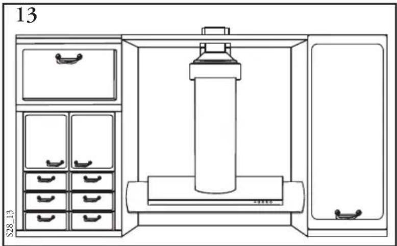
This hood has been designed to be wall-mounted above a cooking hob with one side resting against a wall. It works either by suction (external outlet) or filter (internal recycling).
Because of the complexity and weight of the hood, its installation should be carried out by qualified staff, taking care to respect all local regulations on air discharge.
The manufacturer cannot be found liable for any damage due to improper installation.
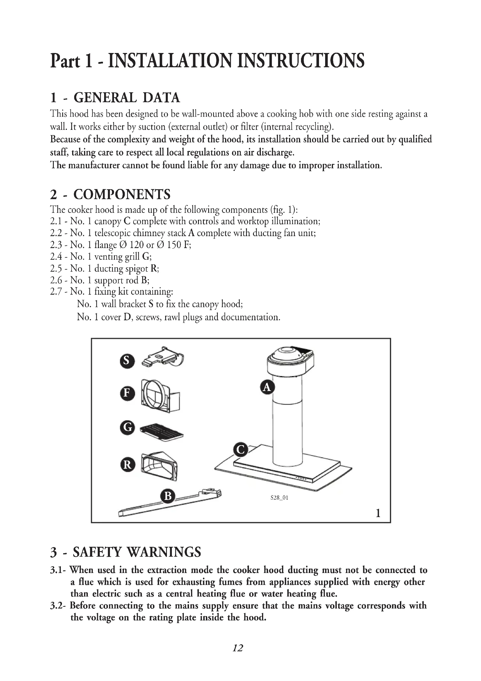
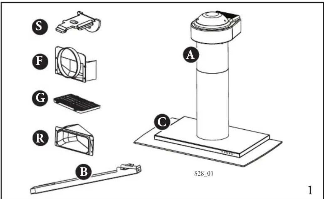
2 - COMPONENTS
The cooker hood is made up of the following components (fig. 1):
2.1 - No. 1 canopy C complete with controls and worktop illumination;
2.2 - No. 1 telescopic chimney stack A complete with ducting fan unit;
2.3 - No. 1 flange 120 or 150 F;
2.4 - No. 1 venting grill G;
2.5 - No. 1 ducting spigot R;
2.6 - No. 1 support rod B;
2.7 - No. 1 fixing kit containing:
No. 1 wall bracket S to fix the canopy hood; No. 1 cover D, screws, rawl plugs and documentation.
3 - SAFETY WARNINGS
3.1- When used in the extraction mode the cooker hood ducting must not be connected to a flue which is used for exhausting fumes from appliances supplied with energy other than electric such as a central heating flue or water heating flue.
3.2- Before connecting to the mains supply ensure that the mains voltage corresponds with the voltage on the rating plate inside the hood.
3.3- Connect the cooker hood to the mains via a double pole switch which has 3mm clearance between the contacts.
3.4- The appliance must be earthed.
3.5- When installed, the hood must be positioned at least 65~cm above a cooking appliance.
3.6- Never do flambe cooking under this cooker hood.
3.7- Never leave frying pans unattended during use as overheated fats and oils may catch fire.
3.8- Before carrying out any kind of maintenance or cleaning, disconnect the hood from the mains supply.
3.9- If the room where the cooker hood is to be used contains a fuel burning appliance such as a central heating boiler then this must be of the room sealed or balanced flue type. If other types of flue or appliance are fitted ensure that there is an adequate supply of air into the room. When the cooker hood is used in conjunction with other appliances supplied with energy other than electric, the negative pressure in the room must not exceed 0,04 mbar to prevent fumes being drawn back into the room by the cooker hood.
4 - INSTALLATION
The versatility of the ducting fan unit on this hood enables it to be installed in one of four different ways:
1 - Air outlet directed upwards (ducting or recirculation fitting).
2 - Air outlet directed towards the wall (ducting fitting only).
3 - Air outlet directed to the right or left (ducting fitting only). For correct installation of the hood, please proceed in the following stages:
4.1 - Selection of the type of installation
4.2 - Installation of the hood canopy C
4.3 - Installation of the chimney A
4.4 - Ducting or recirculation fitting
4.5 - Electrical connection and testing
4.1 - Selecting the type of installation
1 - Air discharge towards the top
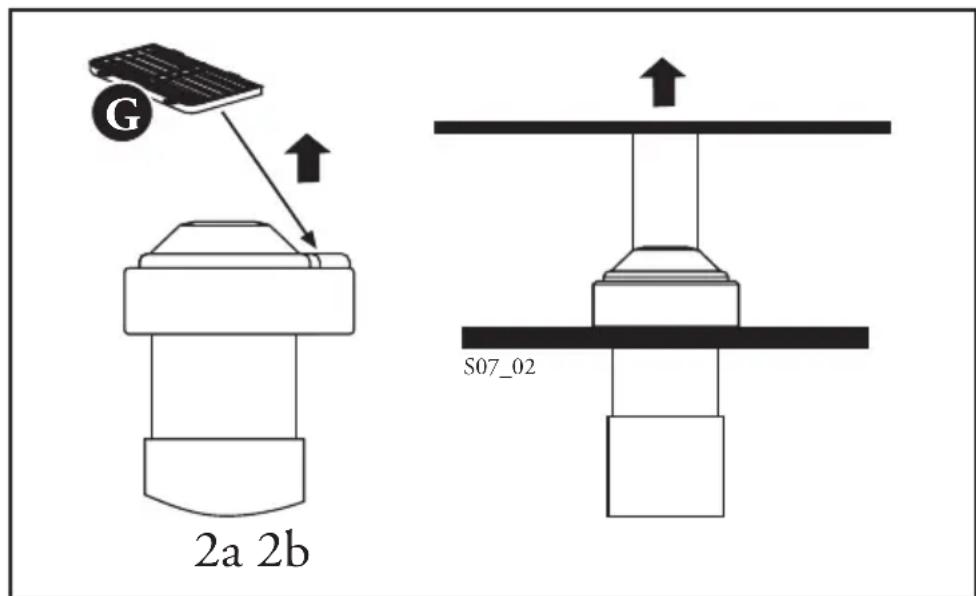
In this case the hood can be used either in filter mode (fig. 2a) or in suction mode (fig. 2b).
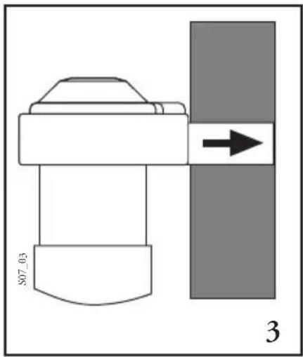
2 - Air discharge towards the wall (fig. 3)
In this case the hood can only be used in suction mode.
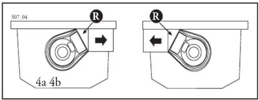
3 - Side air discharge, Lh or Rh (fig. 4a-b).
In this case the hood can only be used in suction mode.
4.2 - Installation of the hood canopy C
1 - Drilling the wall
a) Using the cardboard template provided, mark on the wall the centres of holes 1 for fixing of the hood canopy C. The centre of hole 2 for fixing the chimney, (fig. 5a) air outlet directed upwards or towards the wall, (fig. 5b-c) air outlet to the right or left hand side, must be marked at a distance X from the line between holes 1, obtained by measuring the extension Z of the chimney required for installation, plus 10mm X = Z + 17 - 7 . Using a 8mm drill bit, drill the points marked in this way.
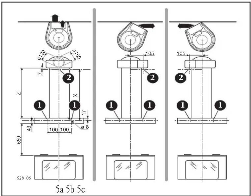
b) When installed with the air outlet directed towards the wall (fig. 5a), it will be necessary to drill an air ducting opening, measuring 120 or 150mm , according to the diameter of the flange F provided.
2 - Fitting the fixing elements
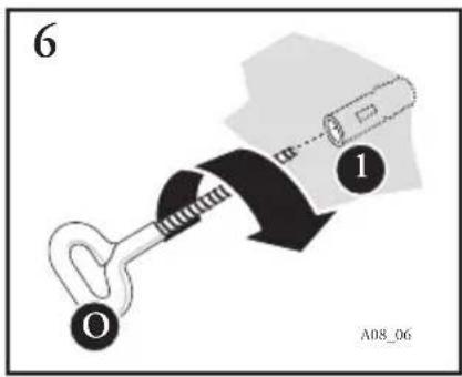
a) Insert the rawl plugs provided into holes 1 and 2.
b) Fit the eye bolts O (fig. 6).
c) Fix the wall bracket S in hole 2 using the screw V provided (fig. 7).

3 - Fitting the hood canopy C to the wall
a) Remove the venting grille and the activated charcoal filter, if there is any (see the paragraph on Maintenance).
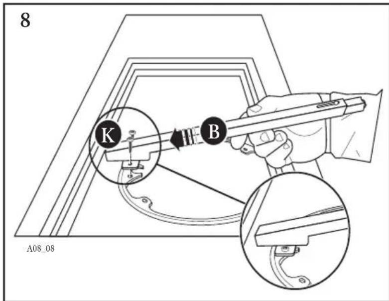
b) Fit the support rod B using the two screws K (3,5x9,5) provided (fig. 8).
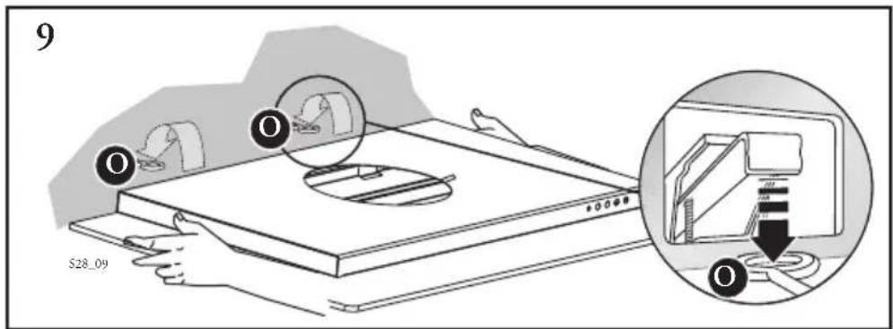
c) Hook the hood canopy C to the eye bolts O fixed in holes 1 (fig.9).
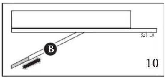
d) Adjust the support rod B so that it pushes against the wall (fig. 10).
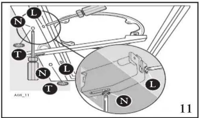
e) Adjusting position (fig. 11). There are two adjustable hooks at the rear of the hood, which can be used to adjust its position as follows:
- Turn the screws L until the position of screws N coincides with the lower access holes.
- Turn the screws N to adjust the vertical and horizontal position of the hood.
-
Lock the screws L to fasten the hood against the wall.
-
Insert the plugs T provided in the holes giving access to screws N.
4.3 - Installation of the chimney A
No matter which type of installation is being used, any wooden shelves in the area where the hood is to be fitted must first be removed, drilled and later replaced.
1 - Drilling the shelves:
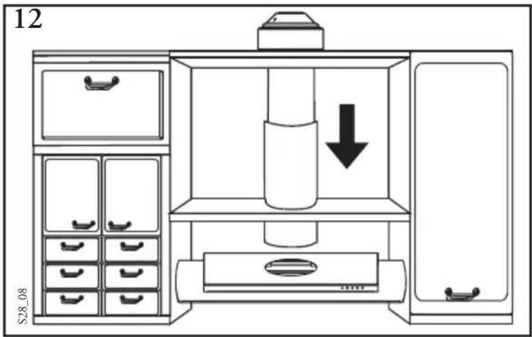
a) Using the cardboard template provided, and taking hole "B" as a point of reference, drill the shelves along the central axis to allow the passage of the chimney. The chimney must be inserted into the shelves before it is fixed to the hood canopy C (fig. 12).
b) When installing the ducting version with the air outlet directed upwards, if the ducting fan unit is positioned below the line of shelves it will be necessary to drill a suitable hole in the top shelf only, to allow the air ducting pipe to pass through (fig. 13).
2 - Direction and position of the ducting fan unit
a) The hood is normally supplied with the air outlet directed
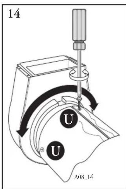
towards the wall (fig. 3), if it is to be installed with the air outlet directed to the right or left (fig. 4a-b), it will be necessary to change the direction of the ducting fan unit, proceeding as follows:
-
Unscrew the screws U (fig. 14);
-
Turn the ducting fan unit 60^ to the right or left;
-
Replace the screws U.
b) The ducting fan unit air outlets must be arranged according to the type of installation to be carried out.
Air outlet directed upwards (fig. 2a-b).
- Remove the plastic plug from the upper part of the venting grill and
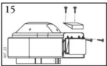
replace it on the rear part (fig. 15).
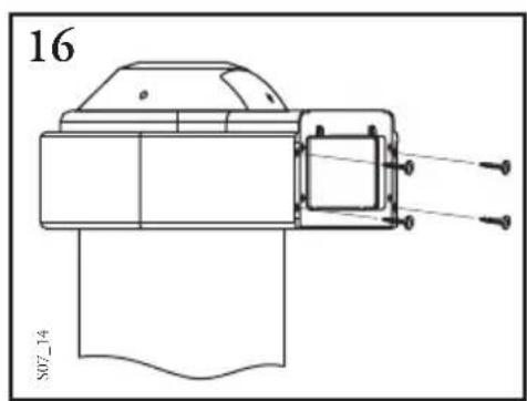
Air outlet directed towards the wall (fig. 3).
- Remove the plastic frame from the air outlet (fig. 16).
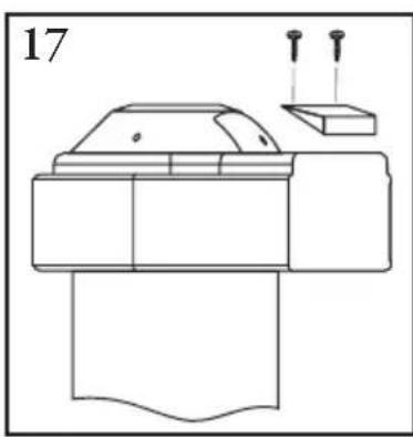
-
Remove the plug from the upper part of the ducting fan unit (fig. 17), as it is not possible to insert the flange F with the plug in place.
-
Fit the flange F 0120 or
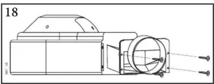
fig. 16.
150mm (fig. 18), replace the plug.
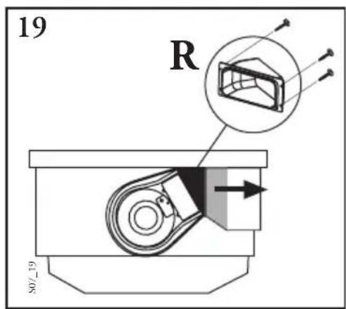
Air outlet directed to the right or left hand side (fig. 4a-b).
- Remove the four screws fastening the plastic frame, as shown in
- Fit the ducting spigot R (fig. 19) and replace the four screws removed as above.
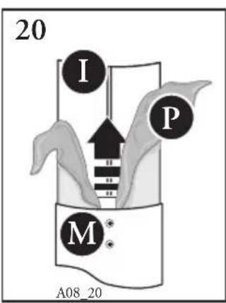
3 - Fixing the chimney
a) Loosen the screws M fixing the two parts of the chimney and pull the inner section I (fig. 20) almost all the way out. Remove the protective film P.
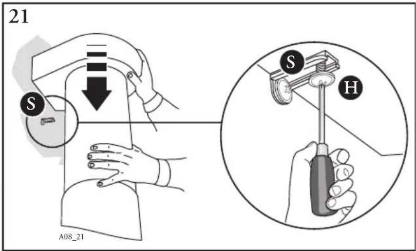
b) Rest the lower section of the chimney in its housing on the top of the hood canopy. Lower the ducting fan unit until it reaches the wall bracket S and fix it using the screw H provided (fig. 21). Fit the cover D
provided) on the wall bracket S (fig. 22).
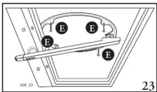
c) Fix the chimney A to the hood canopy C using the four screws provided (fig. 23).
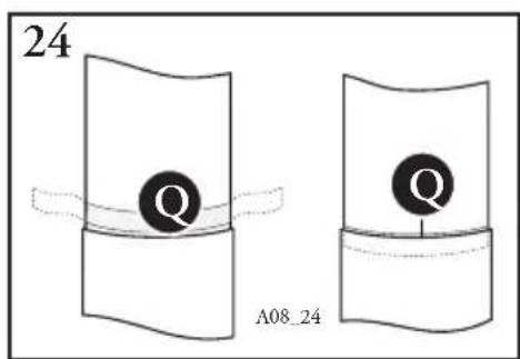
d) Insert the transparent seal Q (provided), so as to eliminate any play between the two parts of the chimney (fig. 24). Lock the screws M.
e) Remove the support rod B.

4.4 - Ducting or recirculation fitting
1 - Ducting fitting.
This is possible for all forms of installation:
a) Connect the air outlet to the external ducting system.
b) Remove the activated charcoal filter (if there is one) inside the hood canopy (see Maintenance).
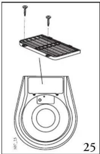
2 - Recirculation fitting
This is only possible with the air outlet directed upwards. Fit the venting grille G onto the air outlet (Fig. 25). The activated charcoal filter should be fitted inside the hood canopy after connection to the power supply.
4.5 - Connection to power supply and checking of good working order
1 - It is absolutely necessary to follow the warnings 3.2, 3.3 and 3.4 of paragraph 3, concerning safety measures.
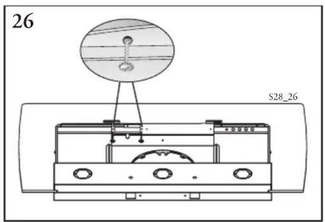
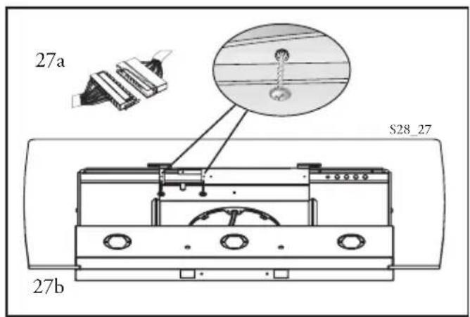
2 - Loosen the two locking screws and remove the metal cover (fig.26).
Connect the hood connection to the engine connection (fig.27a). Correctly place the connectors under the cover and tighten the two locking screws (fig. 27b).
3 - Once electrical connection has been carried out, check that lights, engine and change of speed work
4 - Fit the venting grille and the activated carbon filter, only for filter mode (see Maintenance).
Part 2 - USE AND MAINTENANCE INSTRUCTIONS
1 - SAFETY WARNINGS
It is most important that all the warnings shown in paragraph 3 of the Installation Instructions are strictly observed.
Moreover, pay special attention to the following warnings during the use and maintenance of the cooker hood:
1.1- The grease filters and charcoal filters should be cleaned or replaced as recommended by the manufacturer or more frequently if the hood is used consistently (over 4 hours per day).
1.2- When using a gas hob in connection with the cooker hood never leave the burners of the hob uncovered while the hood is in use or when the pans have been removed. Switch off the gas before removing the pan, or for just short periods and never leave
the hob unattended.
1.3- Always ensure that the flame is kept at the correct intensity to prevent the flame from licking round from the bottom of the pan; this will save energy and will avoid a dangerous concentration of heat.
1.4- Always ensure that the appliance is used in accordance with the manufacturer's instructions for the removal of contaminated air and odours during cooking.
2 - OPERATION
Control panel
The layout of the control is as follows (fig. 28):
BUTTON L = Turns the lighting system on and off;
BUTTON V1 = Turns the on and off at low speed. This is ideal to obtain a particularly silent but continuous flow of air when the level of cooking fumes is

28
V1 V2 V3 L
MID MAX0-10-1


28 2
BUTTON V2 = Medium speed, suitable for most normal operating conditions. This gives an excellent ratio between treated air flow and noise level;
BUTTON V3 = High speed, suitable to deal with heavy cooking fumes, even for long periods of time.
3 - MAINTENANCE
Constant maintenance is a guarantee for long-lasting working order and efficiency.
Special care should be taken of the metal antigrease filter and activated carbon filter (for filter hoods only).
3.1 - Metal antigrease filters
1 - Cleaning
It is necessary to wash these filters at least every two months with a normal detergent; their compact size enables them to be washed also in dishwasher.
2 - Replacement
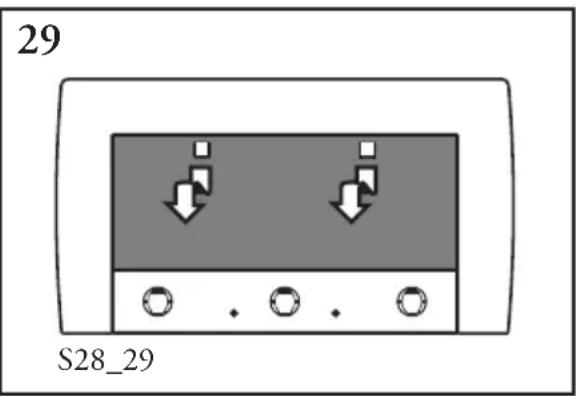
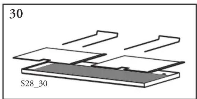
Open the lower grill by pressing the knobs (fig. 29)
Remove the metal filters by taking off the filter holders (fig. 30). Replace the filters after washing and close the lower grill again.
3.2 - Activated carbon filters
1 - How they work
The activated carbon filter can hold odours until it reaches total saturation. It is not washable nor can it be re-used, but should be changed at least every 4 months or more often in case of intensive use.
2 - Replacement
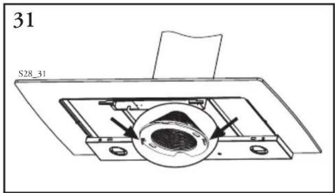
Remove the antigrease filters and the activated carbon filter from its seat by acting on the hooks (fig. 31). Fit the new activated carbon filter and the metal antigrease filters.
WARNING: Maintenance or replacement periods should be respected to avoid any fire hazards when the filters get saturated with grease.
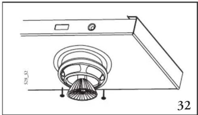
3.3 - Light
1 - It consists of 3 20 W-halogen spotlights.
2 - Replacement (fig. 32)
Remove the two screws that lock the metal ring, take the spotlight out of its holder by pulling slightly. When replacing, make sure that both pins are well inserted in the holder seat.
3.4 - Cleaning
Normal cleaning operation of the hood:
- Do not use any wet cloth or sponge or water-jet.
- Do not use diluents or alcohol, as they could make the painted surfaces opaque.
- Do not use abrasive products, especially on stainless steel surfaces.
We recommend the use of a damp cloth and any neutral liquid detergent.
1ère Partie - INSTRUCTIONS POUR L'INSTALLATION
1 - GENERALITES


- - COMPONENTS
- - SAFETY WARNINGS
- - INSTALLATION
- - Selecting the type of installation
- - Installation of the hood canopy C
- - Drilling the wall
- - Installation of the chimney A
- - Ducting or recirculation fitting
- - Connection to power supply and checking of good working order
- Part 2 - USE AND MAINTENANCE INSTRUCTIONS
- - SAFETY WARNINGS
- - OPERATION
- Control panel
- - MAINTENANCE
- - Metal antigrease filters
- - Cleaning
- - Replacement
- - Activated carbon filters
- - How they work
- - Light
- - Cleaning
- 1ère Partie - INSTRUCTIONS POUR L'INSTALLATION
- - GENERALITES
Brand : Ariston Thermo
Model : HDM 9 IX
Category : Basket