
XH 90 - Basket Ariston Thermo - Free user manual and instructions
Find the device manual for free XH 90 Ariston Thermo in PDF.
| Brand | Ariston Thermo |
| Model | XH 90 |
| Product type | Wall-mounted hood |
| Use | External evacuation or internal recycling |
| Width | 900 mm |
| Minimum distance from cooking surface | 65 cm |
| Connection diameter | 100-150 mm (120-100 reducer supplied) |
| Number of speeds | 3 (V1, V2, V3) |
| Lighting | 3 halogen spots of 20 W each |
| Metal anti-grease filters | Washable (every 2 months) |
| Activated carbon filters | Replaceable (every 4 months) |
| Power supply | 220-240 V, 50 Hz |
| Material | Stainless steel |
| Mounting | Wall-mounted with brackets and rings |
| Controls | Keys: L (light), V1, V2, V3 (ventilation) |
| Routine maintenance | Damp cloth and neutral detergent |
| Supplied accessories | Plugs, screws, rings, reducer sleeve, metal cap |
| Weight | Approximately 15 kg (estimate) |
Frequently Asked Questions - XH 90 Ariston Thermo
User questions about XH 90 Ariston Thermo
0 question about this device. Answer the ones you know or ask your own.
Ask a new question about this device
Download the instructions for your Basket in PDF format for free! Find your manual XH 90 - Ariston Thermo and take your electronic device back in hand. On this page are published all the documents necessary for the use of your device. XH 90 by Ariston Thermo.
USER MANUAL XH 90 Ariston Thermo
natural_image
Line drawing of a kitchen chimney with a cylindrical top and slatted base (no text or symbols)Italiano ...... pag. 3
English ...... pag. 8
Français ...... pag. 13
Deutsch ...... pag. 17
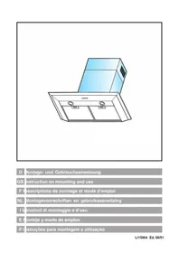
This canopy hood is designed to be fixed to any rigid vertical surface, over a gas or electric hotplate and can be used either in the extraction mode (ducted to the outside) or in the recirculation mode (internal recycling). Before commencing the installation, consi-deration should be given to the difficulties to be found during installation and to the bulky weight of the hood. The installation work must be undertaken by a qualified and competent person in conformity to the rules concerning the evacuation of contaminated air. The manufacturer disclaims all liability for any damage or injury caused as a result of not following the instructions for instal-lation contained in the following text.
2 - COMPONENTS.
The hood comprises (fig. 1):
2.1 - No. 1 canopy C including controls, illumination and fan unit
2.2 - No. 1 telescopic chimney stack comprising:
No. 1 top section S
No. 1 bottom section I
2.3 - No. 1 evacuation spigot A ∅ 120-100
2.4 - No. 1 metal plug T
2.5 - No. 1 plastic bag containing:
screws, plugs, 2 rings D to fix the hood to the wall and documentation
2.6 - No. 1 splashback B (optional).
3 - SAFETY WARNINGS
3.1 - When used in the extraction mode the cooker hood ducting must not be connected to a flue which is used for exhausting fumes from appliances supplied with energy other than electric such as a central heating flue or water heating flue.
3.2 -Before connecting to the mains supply ensure that the mains voltage corresponds with the voltage on the rating plate inside the hood.
3.3 - Connect the cooker hood to the mains via a double pole switch which has 3 mm clearance between the contacts.
3.4 -The appliance must be earthed.
3.5 - When installed, the hood must be positioned at least 65 cm above a cooking appliance.
3.6 -Never do flambé cooking under this cooker hood.
3.7 -Never leave frying pans unattended during use as overheated fats and oils may catch fire.
3.8 -Before carrying out any kind of maintenance or cleaning, disconnect the hood from the mains supply.
3.9 - If the room where the cooker hood is to be used contains a fuel burning appliance such as a central heating boiler then this must be of the room sealed or balanced flue type. If other types of flue or appliance are fitted ensure that there is an adequate
supply of air into the room. When the cooker hood is used in conjunction with other appliances supplied with energy other than electric, the negative pressure in the room must not exceed 0,04 mbar to prevent fumes being drawn back into the room by the cooker hood.
4 - INSTALLATION.
Follow the instructions given below for easy installation:
4.1 - Fixing the canopy hood
4.2 - Electrical connection and working test
4.3 - Ducting or Recirculation fitting
4.4 - Fitting the telescopic chimney stack
4.1 - Fixing the wall brackets. Splashback.
1 - Drilling the wall:
a) Draw a vertical line on the wall at the point in which the hood is to be installed. This line must be at a distance d from the cooker top of:
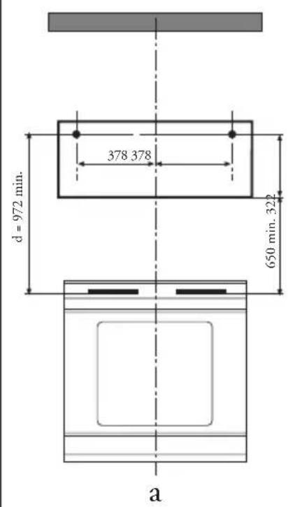
- without splashback (fig. 2a): d=972 mm min.
- with splashback (optional) (fig. 2b): d=322+H mm, where H= height in mm of the visible part of the splashback.
b) On the horizontal line, mark the centres of the two holes to be drilled, at a distance of 378 mm to the right and to the left of the centre of the hood (fig. 2a-b).
c) Using a _ 8 mm drill bit, drill the holes marked, and insert the plugs provided. Screw the ring screws provided in the accessories all the way into he holes.
2 - Splashback (optional).
In this case, the height of the hood above the cooker is determined by the height of the splashback B and by any raised back on the worktops. The splashback must be fitted before fitting the hood canopy, and if it is to be fixed to the wall both at the top and bottom it must be fitted at the right height before fitting the base units, or at least before fitting the worktop. As this is a complicated operation, it should be carried out by the technician responsible for installing the kitchen, or by competent persons with knowledge of the final dimensions of units. To fix the top only, proceed as follows:
a) Rest the splashback on the worktop as shown in (fig. 2a), bring it into contact with the wall and centre it on the base.
b) Mark the centres of the two holes in the upper fold.
c) Drill the wall using a _ 8 mm drill bit, and fix the splashback using the 8 mm plugs and the screws provided.
d) Any stabilisation of the bottom, if required, will be dealt with by the installer.
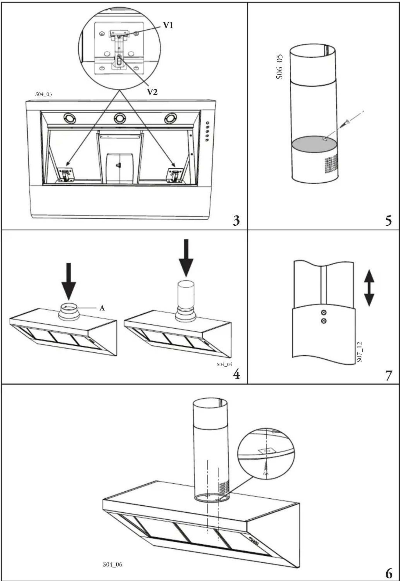
3 - Adjusting and fixing the hood (fig. 3).
The hood is supplied with two adjustable hooks at the back;
a) Hook the hood to the rings.
b) Remove the metal grease filters, in order to access the adjustable hooks from the inside of the hood.
c) Adjust the hood vertically and horizontally by turning the screws V2.
d) Lock the hood against the wall by turning the screws V1 in a clockwise direction.
4.2 - Electrical connection and working test
1 - The safety measures 3.2, 3.3 and 3.4 of paragraph 3 are to be strictly observed.
2 - Once the electrical connection has been completed, check that worktop illumination, motor and speeds work properly.
4.3 - Ducting or Recirculation fitting.
1 - Ducting fitting:
a) The hood can be ducted to the outside using a rigid or flexible ducting pipe ∅ 100 or 150 mm, the choice of which is left to the installer. When ∅ 120 ducting pipe is to be used, it will be necessary to install the reduction flange A on the hood air outlet (fig. 4).
b) Connect the air outlet to the outside using the rigid or flexible ducting pipe, which must be fastened using a suitable pipe connectors. The installer must provide suitable material for this operation.
c) If the hood is provided with charcoal filters, these must be removed (see paragraph 3 3.2-b)
2 - Recirculation fitting:
a) Fix the plug T into the bottom chimney section I, using one of the screws provided in the accessories (fig. 5). The filtered air will be returned to the room through the grille on the chimney itself.
b) Install the activated charcoal filters inside the hood canopy (see paragraph 3 3.2 part 2).
4.4 - Fitting the telescopic chimney stack.
1 - Fixing the chimney (fig. 6).
a) Position the tongues on the bottom section I so that they correspond with the fixing tongues on the hood canopy C, bearing in mind that the slide guide on the two chimney sections must face towards the wall.
b) Fix the chimney to the hood canopy using the two screws provided in the accessories.
2 - Adjusting the telescopic chimney stack (fig. 7).
Unscrew the two screws at the rear of the chimney, adjust the top section S until it is in the position required and then lock the two screws to fix in place.
Part 2 ^a OPERATION AND MAINTENANCE INSTRUCTIONS
1 - SAFETY WARNINGS
It is most important that all the warnings shown in paragr. 3 of the Installation instructions are strictly observed. Moreover pay special attention to the following warnings during the use and maintenance of the cooker hood.
1.1 - The grease filters and the charcoal filter should be cleaned or replaced as recommended by the manufacturer or more frequently if the hood is used consistently (over 4 hours per day).
1.2 - When using a gas hob in conjunction with the cooker hood, never leave the burners uncovered while the hood is in use; when removing the pans either turn the hob off or keep the flame to a minimum if it is only for a few minutes and under supervision.
1.3 - Always ensure that the flame does not overflow from under the pans; this will save energy and will avoid a dangerous concentration of heat.
1.4 - Do not use the appliance in any incorrect way: this hood has been designed only to reduce the smells of cooking in the kitchen.
2 - USE
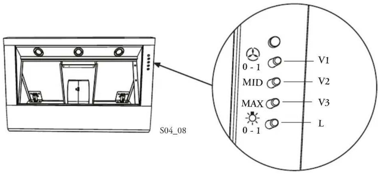
Control panel (fig. 8)
The hood is equipped with the following controls:
BUTTON L = Light ON/OFF
BUTTON V1 = Engine ON/OFF in first speed, suitable for a continuous change of air, noiseless, to be used with little cooking steam.
BUTTON V2 = Second speed, suitable in most conditions of use for its excellent ratio between quantity of treated air and noise level.
BUTTON V3 = Third speed, suitable to cope with major cooking steam emissions even for long periods of time.
3 - MAINTENANCE
Regular maintenance and cleaning will ensure good performance and reliability, while extending the working life of the hood. Special attention should be paid to the grease filters and to the charcoal filters when the hood is used in the recirculation mode.
3.1 - Metal grease filters.
1 - Cleaning:
The filter must be washed with normal household detergent at least once every 2 months. Thanks to its compact shape and size it can also be washed in the dishwasher.
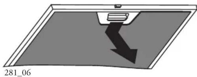
2 - Dismantling the filters:
Remove one filter at a time, pressing the handle towards the back of the hood (fig. 9). When replacing, ensure that the handle remains in a visible position. WARNING - The maintenance periods indicated should always be complied with, to prevent any risk of fire that might result from filters saturated with grease.
3.2 - Activated charcoal filter.
1 - Operation:
The activated charcoal filters will capture bad smells until they reach saturation. They cannot be washed or recycled, and must be replaced at least once every 4 months, or more frequently if subjected to particularly intense use.
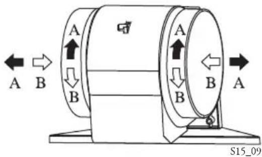
2 - Replacing:
Remove the metal grease filters or the ducting grille, remove the activated charcoal filters situated at the ends of the fans, turning them in the direction shown by the arrows A. Fit the new filters, turning them in the direction shown by the arrows B (fig. 10).
3.3 - Light
1 - It consists of 3 20 W-halogen spotlights.
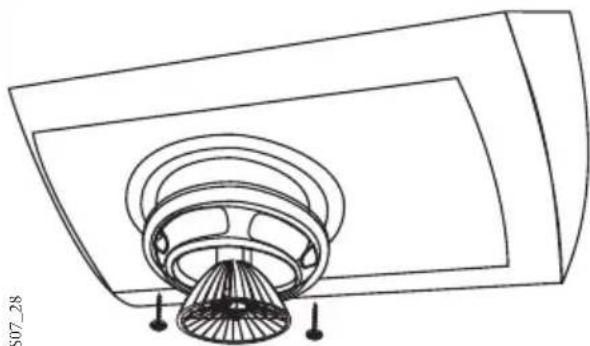
2 - Replacement (fig. 11)
Remove the two screws that lock the metal ring, take the spotlight out of its holder by pulling
slightly. When replacing, make sure that both pins are well inserted in the holder seat.
3.4 - Cleaning
When cleaning the hood:
- Never use a wet cloth or sponge, or running water.
- Never use thinners or products containing alcohol, as they might damage the paintwork.
- Never use abrasive cleaning materials, in particular when cleaning stainless steel surfaces.
It is recommended to use a damp cloth and mild liquid household cleaner.
1ère Partie INSTRUCTIONS POUR L'INSTALLATION
1 - GENERALITES
1

2
natural_image
Diagram showing a device with a downward arrow inside a rectangular frame, labeled '281_06' at bottom left (no other text or symbols)9
10
natural_image
Technical line drawing of a ceiling fan assembly with mounting holes (no text or symbols)11
A01055e1


- - COMPONENTS.
- - SAFETY WARNINGS
- - INSTALLATION.
- - Fixing the wall brackets. Splashback.
- - Electrical connection and working test
- - Ducting or Recirculation fitting.
- - Fitting the telescopic chimney stack.
- Part 2 a OPERATION AND MAINTENANCE INSTRUCTIONS
- - SAFETY WARNINGS
- - USE
- - MAINTENANCE
- - Metal grease filters.
- - Activated charcoal filter.
- - Light
- - Cleaning
- 1ère Partie INSTRUCTIONS POUR L'INSTALLATION
- - GENERALITES
Brand : Ariston Thermo
Model : XH 90
Category : Basket