
EY78A1 - Screwdriver PANASONIC - Free user manual and instructions
Find the device manual for free EY78A1 PANASONIC in PDF.
| Product Type | Cordless Hammer Drill/Driver |
| Brand | Panasonic |
| Model | EY78A1 |
| Rated voltage | 18 V DC |
| Battery type | Li-ion (compatible models: EY9L41, EY9L42, EY9L44, EY9L45, EY9L50, EY9L51) |
| Battery charger | EY0L81 or EY0L82 |
| No-load speed | 0 – 1250 rpm |
| Impact rate | 4750 bpm |
| Max drilling diameter (concrete) | 16.5 mm |
| Max drilling diameter (steel) | 13 mm |
| Max drilling diameter (wood) | 18 mm |
| Adjustable torque | 5 levels + drilling mode (max ~13.5 N·m) |
| Total length | 249 mm |
| Weight (with battery EY9L51) | 2.6 kg |
| Lighting | Built-in LED with on/off button |
| Protections | Motor/battery overheating protection, over-discharge protection |
| Bit attachment system | SDS Plus (with adapter for cylindrical bits) |
| Included accessories | Bit adapter, wrist strap |
| Maintenance | Soft, dry cloth; do not use solvents |
| Intended use | Drilling concrete, metal, wood; screwdriving |
Frequently Asked Questions - EY78A1 PANASONIC
User questions about EY78A1 PANASONIC
0 question about this device. Answer the ones you know or ask your own.
Ask a new question about this device
Download the instructions for your Screwdriver in PDF format for free! Find your manual EY78A1 - PANASONIC and take your electronic device back in hand. On this page are published all the documents necessary for the use of your device. EY78A1 by PANASONIC.
USER MANUAL EY78A1 PANASONIC
Cordless Rotary Hammer Drill & Driver
natural_image
Line drawing of a handheld electronic device with no visible text or symbolsBefore operating this unit, please read these instructions completely and save this manual for future use. Vor Inbetriebnahme des Gerätes die Betriebsanleitung bitte gründlich durchlesen und diese Broschüre zum späteren Nachschlagen sorgfältig aufbewahren. Lire entièrement les instructions suivantes avant de faire fonctionner l'appareil et conserver ce mode d'emploi à des fins de consultation ultérieure. Prima di usare questo apparecchio, leggere completamente queste istruzioni e conservare il manuale per usi futuri. Lees deze gebruiksaanwijzing aandachtig door voor u het apparaat in gebruik neemt en bewaar de gebruiksaanwijzing voor eventuele naslag. Antes de usar este aparato por primera vez, lea todas las instrucciones de este manual y guarde el manual para poderlo consultar en el futuro. Gennemlæs denne betjeningsvejledning før brugen og gem den til fremtidig brug. Läs igenom hela bruksanvisningen innan produkten tas i bruk. Spara bruksanvisningen för senare användning. Før enheten tas i bruk, vennligst les disse alle anvisningene og oppbevar bruksanvisningen for senere bruk. Lue ohjeet huolella ennen laitteen käyttöönottoa ja säilytä tämä käyttöohje tallessa tulevaa tarvetta varten.
Index/Index/Index/Indice/Index/Indice/Indeks/Index/Indeks/Hakemisto
English: Page 9
Deutsch: Seite 23
Français: Page 38
Italiano: Pagina 52
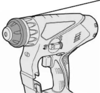
| (A) | ChuckFutterMandrinoMandrinoBoorkopPortabrocaBorepatronChuckChuckKiinnityslaite | (B) | Clutch handleKupplungsringPoignée de l'embrayageImpugnatura frizioneKoppelingshandgreepMango de embragueKoblinghåndtagKopplingshandtagKoblingshåndtakKytkimen kahva |
| (C) | Hammering/drilling switching leverZum Umschalten zwischen normalem Bohren und SchlagbohrenCommutateur martelage/perforationLeva di commutazione martellatura/perforazioneKeuzehendel normaal boren/klopborenPalanca de conmutación de martillo/taladroHamrings/borings omskiftningsgrebOmkopplare mellan slagborr/vanlig borrSlag/bor omskifterVasaran/poran kytkentävipu | (D) | Forward/Reverse leverRechts/Linkslauf SchalterLevier d'inversion marche avant-marche arrièreLeva di avanzamento/inversioneVoorwaarts/achterwaarts-hendelPalanca de avance/inversiónGreb til forlæns/baglæns retningRiktningsomkopplareForover/Revers bryterEteenpäin/taaksepäin vp u |
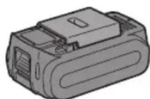
| (E) | Variable speed control triggerBetriebsschalterGächette de commande de vitesseGrilletto di controllo velocità variableStartschakelaar variabele snelheidDisparador del control de velocided variableKontroludlöser for variabel hastighedSteglös varvtalsreglerareHovedbryter, trinnløsNopeudensäätökytkin | (F) | Battery packAkkuBatterie autonomePacco batteriaAccuBateriABatteripakningBatteriBatteripakkeAkku |
| (G) | Alignment marksAusrichtmarkierungenMarques d'alignementMarcature allineamentoUitlijntekensMarcas de alineaciónFlugtemærkerAnpassningsmärkenOpprettingsmerkeSovitusmerkit | (H) | Control panelBedienfeldPanneau de commandePannello di controlloBedieningspaneelPanel de controleKontrollpanelKontrollpanelKontrollpanelSäätö paneeli |
| (I) | Overheat warning lamp (battery)Überhitzungs-Warnlampe (Akku)Témoin d'avertissement de surchauffe (batterie)Spia avvertenza surriscaldamento (batteria)Oververhitting-waarschuwingslampje (accu)Luz de advertencia de sobrecalentamiento (bateria)Advarselslamp til overophedning (batteri)Varningslampa för överhettning (batteri)Varsellampe for overoppheting (batteri)Ylikuumenemisen varoituslamppu (akku) | (J) | LED light on/off buttonLED-Leuchten-EIN/AUS-TasteBouton Marche/Arrêt de la lumière DELTasto di accensione e spegnimento della luce LEDAan/uit-toets (ON/OFF) voor LED-lampjeBotón ON/OFF de luz LEDTÄEND/SLUK-knap til LED-lysStrömbrytare för LED-ljusPÄ/AV-knapp for LED-lysLED-valon kytkin/katkaisupainike |
| (K) | Battery low warning lampAkkuladungs-WarnlampeTémoin d'avertissement de batterie basseSpia avvertenza batteria scaricaWaarschuwingslampje voor lage accuspanningLuz de aviso de baja carga de bateríaAdvarselslampes batterieffekt lavVarningslampa för svagt batteriVarsellampe for at batteriet er for lavtAlhaisen akku jännitteen varoituslamppu | (L) | Battery pack release buttonAkku-EntriegelungsknopfBouton de libération de batterie autonomeTasto di rilascio pacco batteriaAccu-ontgrendeltoetsBotón de liberación de bateríaUdløserknap til batteripakningFrigöringsknapp för batteriUtløserknapp for batteripakkeAkkupaketin irrotuspainike |
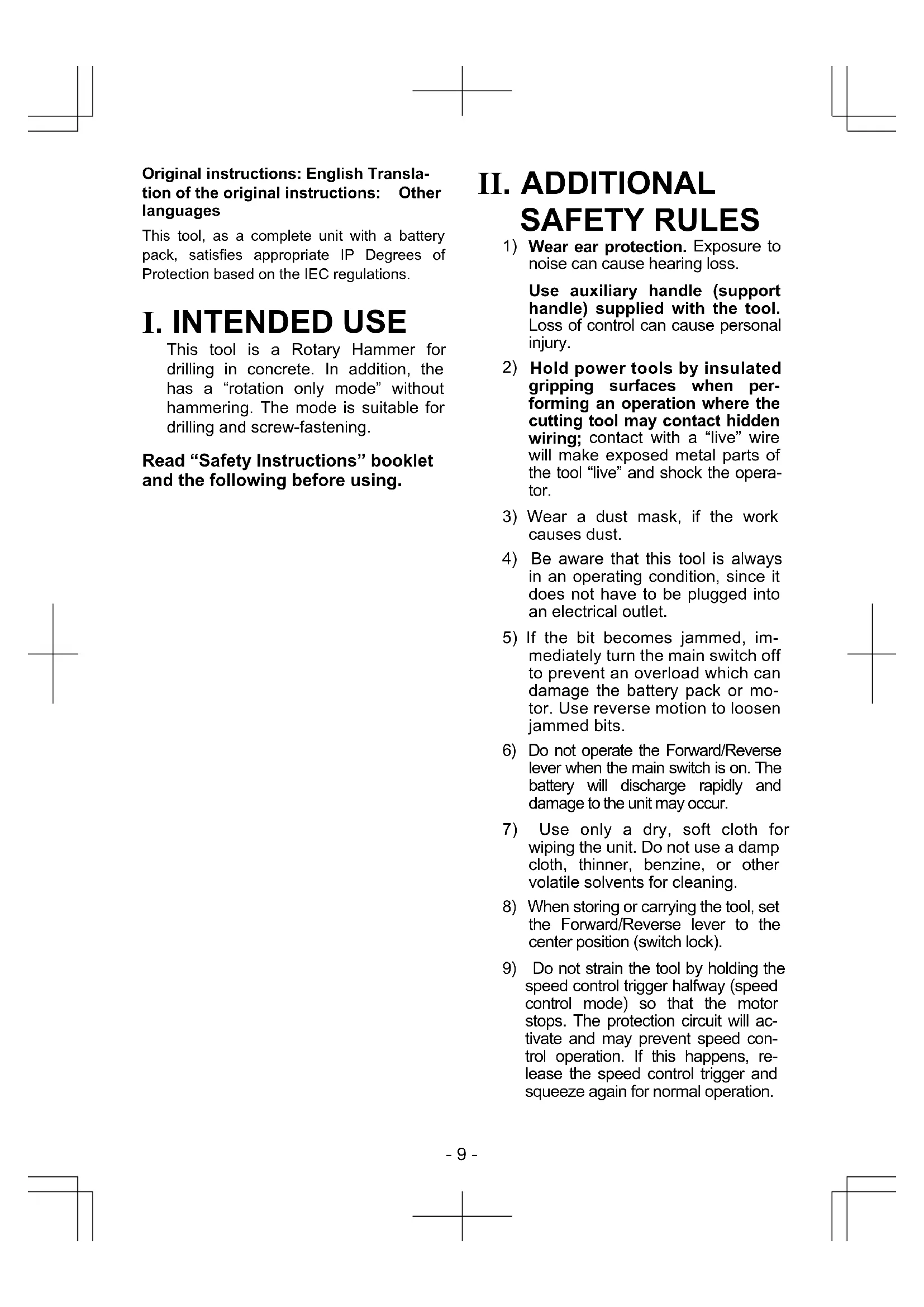
| (M)(O) | Bit adapter holderEinsatzadapterhalterPorte-adaptateur de mècheAdattatore di portabitBitadapterhouderSoporte de adaptador de brocaBoradapterholderHållare för verktygsspetsadapterHolderstykke for bit-tilpasningsstykkeTerän sovittimen pidinBit adapter (EY9HX403E)Einsatzadapter (EY9HX403E)Adaptateur de mèche (EY9HX403E)Portabit (EY9HX403E)Bitadapter (EY9HX403E)Adaptador de broca (EY9HX403E)Boradapter (EY9HX403E)Verktygsspetsadapter (EY9HX403E)Bitholderen (EY9HX403E)Bitsi adapteri (EY9HX403E) | (N)(P) | LED lightLED-LeuchteLumière DELLuce LEDLED-lampjeLuz indicadoraLED-lysLED-ljusLED-lysLED-valoShoulder strapSchulterriemenDragonneCinghia da spallaSchouderriemCorrea al hombroSkulderremAxelremSkulderbelteOlkahihna |
| (Q) | Battery chargerLadegerätChargeur de batterieCaricabatterieAcculaderCargador de bateríaBatteriopladerBatteriladdareBatteriladerAkkulaturi | (R) | Pack coverAkkuabdeckungCouvercle de la batterie autonomeCoperchio paccoAccudekselCubierta de bateríaPakningsdækselBatteriskyddPakkedekselAkkukotelon kansi |
Recommendations for use / Gebrauchsempfehlungen / Recommandations concernant l'utilisation / Precauzioni d'uso / Aanbevelingen voor gebruik / Recomendaciones par el uso / Anbefalinger for brugen / Rekommendationer för användning / Anbefalt bruk / Käyttösuositukset
| Pack cover | Cubierta de batería |
| Akkuabdeckung | Pakningsdæksel |
| Couvercle de la batterie autonome | Batteriskydd |
| Coperchio pacco | Pakkedeksel |
| Accudeksel | Akkukotelon kansi |
| label | label | etikett |
| Schild | rojo | merkki |
| rouge | etikette | |
| rossa | dekal |
natural_image
Diagram of a computer case with an open lid and a magnified inset showing internal components (no text or symbols)| Terminals | Terminales |
| Anschlüsse | Terminaler |
| Bornes | Poler |
| Terminali | Ender |
| Aansluitpunten | Liittimet |
GB
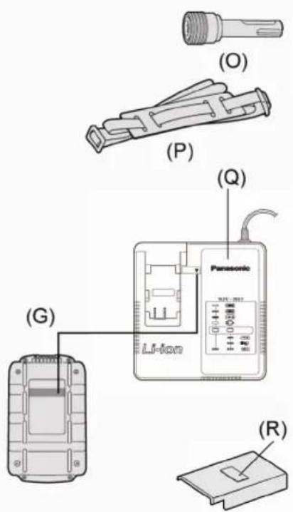
Be sure to use the Pack cover
- When the battery pack is not being used, store the battery in a way that foreign substances such as dust and water etc. do not contaminate the terminals. Be sure to attach the battery pack cover to protect the battery terminals.
- When charging the battery pack, confirm that the terminals on the battery charger are free of foreign substances such as dust and water etc. Clean the terminals before charging the battery pack if any foreign substances are found on the terminals.
The life of the battery pack terminals may be affected by foreign substances such as dust and water etc. during operation.
CAUTION: To protect the motor or battery, be sure to note the following when carrying out this operation.
- If the motor or battery becomes hot, the protection function will be activated and the motor or battery will stop operating.
The overheat warning lamp on the control panel illuminates or flashes when this feature is active.
For safe use
- The battery pack is designed to be installed by proceeding two steps for safety. Make sure the battery pack is installed properly to the main body before use.
- If the battery pack is not inserted firmly when the switch is switched on, the overheat warning lamp and the battery low warning lamp will flash to indicate that safe operation is not possible, and the bit will not rotate normally. Insert the battery pack into the body of the tool until the red label disappears.
D
Original instructions: English Translation of the original instructions: Other languages
This tool, as a complete unit with a battery pack, satisfies appropriate IP Degrees of Protection based on the IEC regulations.
I. INTENDED USE
This tool is a Rotary Hammer for drilling in concrete. In addition, the has a “rotation only mode” without hammering. The mode is suitable for drilling and screw-fastening.
Read "Safety Instructions" booklet and the following before using.
II. ADDITIONAL SAFETY RULES
1) Wear ear protection. Exposure to noise can cause hearing loss.
Use auxiliary handle (support handle) supplied with the tool. Loss of control can cause personal injury.
2) Hold power tools by insulated gripping surfaces when performing an operation where the cutting tool may contact hidden wiring; contact with a "live" wire will make exposed metal parts of the tool "live" and shock the operator.
3) Wear a dust mask, if the work causes dust.
4) Be aware that this tool is always in an operating condition, since it does not have to be plugged into an electrical outlet.
5) If the bit becomes jammed, immediately turn the main switch off to prevent an overload which can damage the battery pack or motor. Use reverse motion to loosen jammed bits.
6) Do not operate the Forward/Reverse lever when the main switch is on. The battery will discharge rapidly and damage to the unit may occur.
7) Use only a dry, soft cloth for wiping the unit. Do not use a damp cloth, thinner, benzine, or other volatile solvents for cleaning.
8) When storing or carrying the tool, set the Forward/Reverse lever to the center position (switch lock).
9) Do not strain the tool by holding the speed control trigger halfway (speed control mode) so that the motor stops. The protection circuit will activate and may prevent speed control operation. If this happens, release the speed control trigger and squeeze again for normal operation.
10) Be careful not to get dust inside the chuck.
11) Do not touch the rotating parts to avoid injury.
12) Do not continue to use the tool for a long time. Stop using the tool from time to time to avoid that the temperature of the motor rises too high.
13) Do not drop the tool.
14) Do not put the tool on the place where the chuck is depressed. The bit may come off from the chuck and fall down when the chuck is depressed. It may cause injuries.
| Symbol | meaning |
| V | Volts |
| --- | Direct current |
| n_b | No load speed |
| ...min ^-1 | Revolutions orreciprocation per minutes |
| Rotation with hammering | |
| Rotation | |
| To reduce the risk ofinjury, user must readand understand instruc-tion manual. | |
| For indoor use only. |
WARNING:
- Do not use other than the Panasonic battery packs that are designed for use with this rechargeable tool.
- Panasonic is not responsible for any damage or accident caused by the use of the recycled battery pack and the counterfeit battery pack.
- Do not dispose of the battery pack in a fire, or expose it to excessive heat.
- Do not drive the likes of nails into the battery pack, subject it to shocks, dismantle it, or attempt to modify it.
- Do not allow metal objects to touch the battery pack terminals.
- Do not carry or store the battery pack in the same container as nails or similar metal objects.
- Do not charge the battery pack in a high-temperature location, such as next to a fire or in direct sunlight. Otherwise, the battery may overheat, catch fire, or explode.
- Never use other than the dedicated charger to charge the battery pack. Otherwise, the battery may leak, overheat, or explode.
• After removing the battery pack from the tool or the charger, always reattach the pack cover. Otherwise, the battery contacts could be shorted, leading to a risk of fire. - When the Battery Pack Has Deteriorated, Replace It with a New One. Continued use of a damaged battery pack may result in heat generation, ignition or battery rupture.
III. ASSEMBLY
CAUTION:
Use of a concrete drill bit larger than the recommended size may cause damage to the tool.
1. To insert the bit
1-1. Insert a bit into the mounting hole, and turn it slightly to locate an engaged position.
1-2. At the engaged position, push the bit as far as it goes. Make sure that the bit is fixed by pulling it.
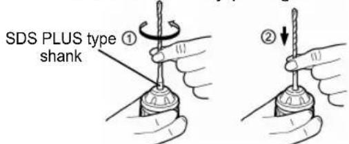
2. To remove the bit
2-1. Depress the chuck and pull the bit.
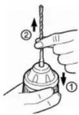
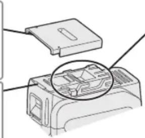
Bit adapter
Use a bit adapter (O) and bit.
- Remove the bit adapter from the bit adapter holder on the main unit.
- Pull the bit holder. (1)
- Insert the bit. (②)
- Make sure the bit is inserted firmly by pulling it lightly.
- Insert the bit adapter into the holder mounting hole and turn to locate an engaged position.
- At the engaged position, push in as far as it goes.
• Make sure it does not move by pulling it lightly.
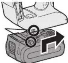
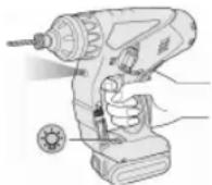
Attaching or Removing Battery Pack
- To connect the battery pack:
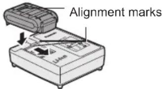
Line up the alignment marks and attach the battery pack.
- Slide the battery pack until it locks into position.
Alignment marks
natural_image
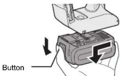
Illustration of a printer with a paper roll and a magnifying glass, showing a 3D printing press (no text or symbols)- To remove the battery pack:
Pull the button from the front to release the battery pack.
IV. OPERATION
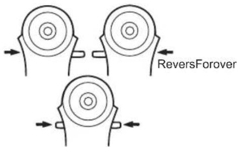
Forward/Reverse Lever
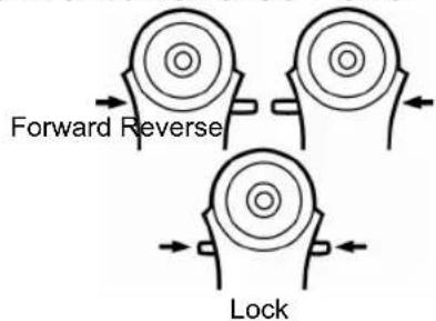
- Be sure to set the lever in the center to lock it after use.
- Operate the Forward/Reverse lever after the motor rotation is completely stopped.
Hammering/Drilling Switching Lever
NOTE: Operate the mode change after the motor rotation is completely stopped.
| Position of switching lever | Action mode | Operation |
 | Rotation with hammering | Concrete Drilling, Block Drilling |
 | Rotation only | Screw Fastening, Drilling |
Clutch Torque Setting
Adjust the torque to one of the 5 clutch settings or “#” position.
CAUTION:
Test the setting before actual operation.
Set the scale at this mark (◀).
natural_image
Line drawing of a handheld electric drill putter with handle and control panel (no text or symbols)Variable Speed Control Trigger
To set the center of a hole, pull the trigger slightly to start the drill rotation slowly.
The more the speed control trigger is pulled, the higher the speed becomes.
CAUTION:
When operating the tool by pulling the trigger, there may be a momentary lag before rotation starts. This does not signal a malfunction.
- This lag occurs as the tool's circuitry starts up when the trigger is pulled for the first time after installing a new battery pack or after the tool has not been used for at least 1 minute (or at least 5 minutes when the LED is on). Rotation will start without any lag during second and subsequent operations.
Control Panel
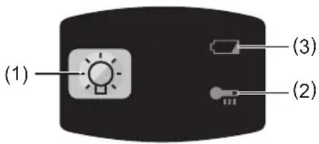
(1) LED light
Before the use of LED light, always pull the power switch once.
Press the LED light on button.
The light illuminates with very low current, and it does not adversely affect the performance of the tool during use or its battery capacity.
CAUTION:
- The built-in LED light is designed to illuminate the small work area temporarily.
- Do not use it as a substitute for a regular flashlight, since it does not have enough brightness.
- LED light turns off when the tool has not been used for 5 minutes.
Caution : DO NOT STARE INTO BEAM. Use of controls or adjustments or performance of procedures other than those specified herein may result in hazardous radiation exposure.
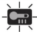
(2) Overheat warning lamp


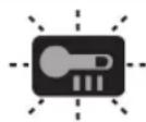
Off
(normal
operation)
Illuminated:
Overheat
(motor)
Flashing:
Overheat
(battery)
Indicates operation has
been halted due to motor
or battery overheating.
To protect the motor or battery, be sure to note the following when carrying out this operation.
- If the motor or battery becomes hot, the protection function will be activated and the motor or battery will stop operating. The overheat warning lamp on the contropanel
illuminates or flashes when this feature is active.
- If the overheating protection feature activates, allow the tool to cool thoroughly (at least 30 minutes). The tool is ready for use when the overheat warning lamp goes out.
- Avoid using the tool in a way that causes the overheating protection feature to activate repeatedly.
- If the tool is operated continuously under high-load conditions or if it is used in hot-temperature conditions (such as during summer), the overheating protection feature may activate frequently.
- If the tool is used in cold-temperature conditions (such as during winter) or if it is frequently stopped during use, the overheating protection feature may not activate.
- The performance of the EY9L42 deteriorates significantly at and below 10^ due to work conditions and other factors.
- The ambient temperature range is between 0^ (32°F) and 40^ (104°F). If the battery pack is used when the battery temperature is below 0^ (32°F), the tool may fail to function properly.
- Use the charger at temperatures between 0^ and 40^ , and charge the battery at a temperature similar to that of the battery itself. (There should be no more than a 15^ difference between the temperatures of the battery and the charging location.)
(3) Battery low warning lamp
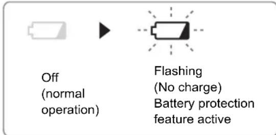
Excessive (complete) discharging of lithium ion batteries shortens their service life dramatically. The driver includes a battery protection feature designed to prevent excessive discharging of the battery pack.
- The battery protection feature activates immediately before the battery loses its charge, causing the battery low warning lamp to flash.
- If you notice the battery low warning lamp flashing, charge the battery pack immediately.
- If it is started with too little battery power remaining, the tool may stop operating without the battery low warning lamp flashing first. This indicates that there is too little battery power remaining to use the tool, and the battery pack should be charged before further use.
- If the tool is subject to a sudden load during use that causes the motor to lock up, the overdischarge prevention sensor may be triggered, and the battery low warning lamp may flash. The lamp will stop flashing once you address the cause of the motor's locking up and cycle the trigger.
natural_image
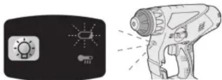
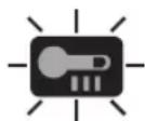
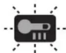
Illustration of a sunlight and a handheld device with motion lines (no text or symbols)- The battery protection feature may activate when a high load is abruptly placed on the motor, even if ample battery charge remains. In this case, both the battery low warning lamp and LED light will flash. (EY78A1)
- If both the battery low warning lamp and LED light flash, reduce the force with which you are pushing on the driver or, if using a drill driver, adjust the speed switch to a lower setting. (EY78A1)
Installing the Shoulder Strap
CAUTION:
• Install the shoulder strap firmly to the main unit of the tool and check the length of the strap before use.
- Check the condition of the strap and do not use if it is cut or torn etc.
There is a risk of injury or damage if used while improperly installed.
- Please wear the shoulder strap securely on the shoulder. There is a risk of injury or damage if it is accidentally dropped.
- Pass the strap through the strap holders. (①)
- Pass the strap through the buckles and adjust the length. (②)
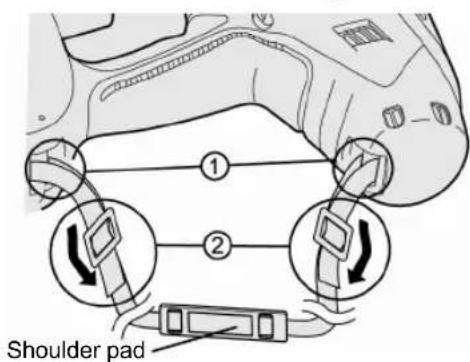
- The shoulder strap can be adjusted according to the individual.
- Adjust the shoulder pad to the shoulder.
- Pull the shoulder strap to make sure it is firmly attached to the main unit of the tool.
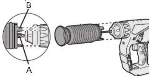
Dust Collection Cup (EY9X005E) (Available as an optional accessory)
* Drill bits of which diameter is 20 mm above cannot be inserted through dust collection cup.
* Do not use the tool for cutting other than concrete, mortar and other ceramic materials. If used for cutting metal materials, the dust collection cup may be damaged by the metal chip heat.
* Do not use this tool with any drill bit which is shorter than 130 mm in length.
-
Install a drill bit.
-
Pass the drill bit through A and fix the cup at B by matching with the shape of the cluch handle.
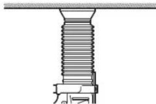
Operation
Keep the dust collection cup in close contact with the wall surface during operation.
natural_image
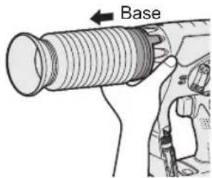
Technical line drawing of a threaded fastener assembly (no text or symbols)Removal
Hold the base of the dust collection cup for removal.
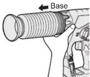
Please remove after thoroughly getting rid of the dust in the dust collection cup.
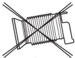
Storage
Do not store the dust collection cup in a compressed position. If kept in a compressed position, it may be impossible to return to the original shape.
natural_image
Pure mechanical diagram showing a spring with intersecting lines, no text or symbols present[Battery Pack]
For Appropriate Use of Battery pack
- For optimum battery life, store the Li-ion battery pack following use without charging it.
- When charging the battery pack, confirm that the terminals on the battery charger are free of foreign substances such as dust and water etc. Clean the terminals before charging the battery pack if any foreign substances are found on the terminals.
The life of the battery pack terminals may be affected by foreign substances such as dust and water etc. during operation.
- When battery pack is not in use, keep it away from other metal objects like: paper clips, coins, keys, nails, screws, or other small metal objects that can make a connection from one terminal to another.
Shorting the battery terminals together may cause sparks, burns or a fire.
- When operating the battery pack, make sure the work place is well ventilated.
- When the battery pack is removed from the main body of the tool, replace the battery pack cover immediately in order to prevent dust or dirt from contaminating the battery terminals and causing a short circuit.
Battery Pack Life
The rechargeable batteries have a limited life. If the operation time becomes extremely short after recharging, replace the battery pack with a new one.
Battery Recycling
ATTENTION:
For environmental protection and recycling of materials, be sure that it is disposed of at an officially assigned location, if there is one in your country.
[Battery Charger]
Charging
Cautions
- If the temperature of the battery pack falls approximately below -10^ (14°F), charging will automatically stop to prevent degradation of the battery.
- The ambient temperature range is between 0^ (32°F) and 40^ (104°F).
If the battery pack is used when the battery temperature is below 0^ C ( 32^ F), the tool may fail to function properly.
- Use the charger at temperatures between 0^ and 40^ , and charge the battery at a temperature similar to that of the battery itself. (There should be no more than a 15^ difference between the temperatures of the battery and the charging location.)
-
When charging a cool battery pack (below 0^ (32^) ) in a warm place, leave the battery pack at the place and wait for more than one hour to warm up the battery to the level of the ambient temperature.
-
Cool down the charger when charging more than two battery packs consecutively.
- Do not insert your fingers into contact hole, when holding charger or any other occasions.
CAUTION:
To prevent the risk of fire or damage to the battery charger.
- Do not use power source from an engine generator.
- Do not cover vent holes on the charger and the battery pack.
- Unplug the charger when not in use.
Li-ion Battery Pack
NOTE:
Your battery pack is not fully charged at the time of purchase. Be sure to charge the battery before use.
Battery charger
- Plug the charger into the AC outlet.
- Insert the battery pack firmly into the charger.
- Line up the alignment marks and place the battery onto the dock on the charger.
- Slide forward in the direction of the arrow.
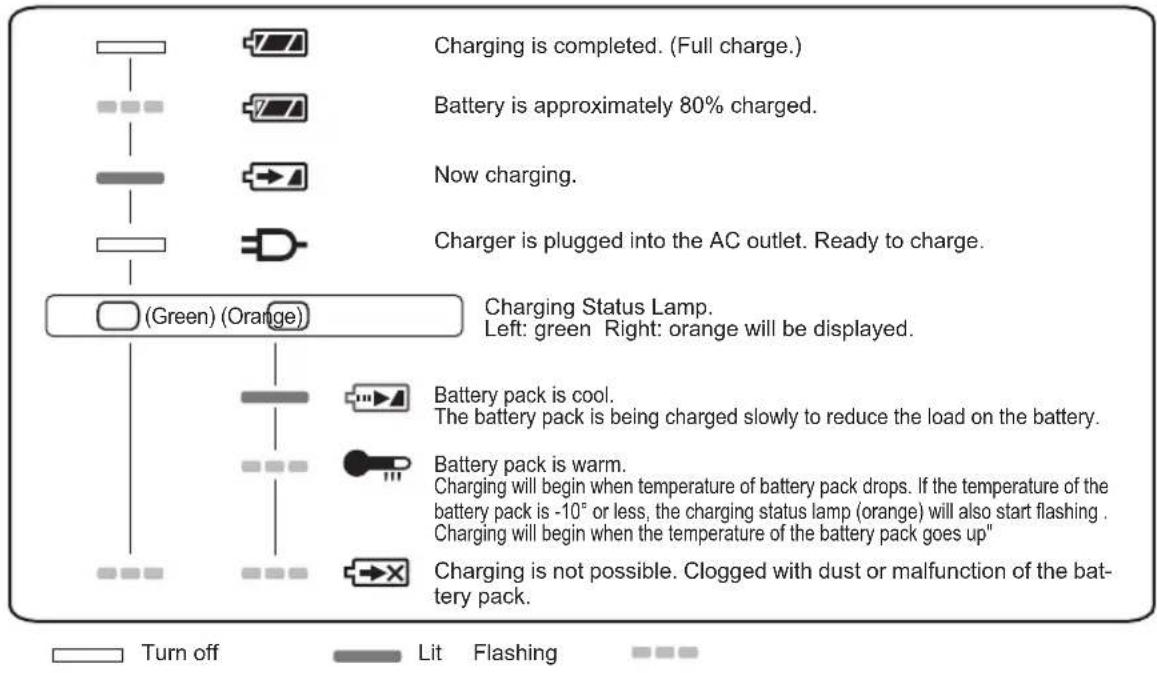
- During charging, the charging lamp will be lit.
When charging is completed, an internal electronic switch will automatically be triggered to prevent overcharging.
- Charging will not start if the battery pack is warm (for example, immediately after heavy-duty operation). The orange standby lamp will be flashing until the battery cools down.
Charging will then begin automatically.
- The charge lamp (green) will flash slowly once the battery is approximately 80% charged.
-
When charging is completed, the charging lamp in green color will turn off.
-
If the temperature of the batter pack is 0^ C or less, charging takes longer to fully charge the battery pack than the standard charging time.
Even when the battery is fully charged, it will have approximately 50% of the power of a fully charged battery at normal operating temperature. - Consult an authorized dealer if the charging lamp (green) does not turn off.
- If a fully charged battery pack is inserted into the charger again, the charging lamp lights up. After several minutes, the charging lamp in green color will turn off.
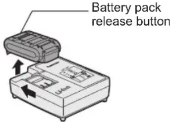
- Remove the battery pack while the battery pack release button is held up.
LAMP INDICATIONS
Information for Users on Collection and Disposal of Old Equipment and used Batteries
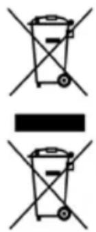
These symbols on the products, packaging, and/or accompanying documents mean that used electrical and electronic products and batteries should not be mixed with general household waste.
For proper treatment, recovery and recycling of old products and used batteries, please take them to applicable collection points, in accordance with your national legislation and the Directives 2002/96/EC and 2006/66/EC.
By disposing of these products and batteries correctly, you will help to save valuable resources and prevent any potential negative effects on human health and the environment which could otherwise arise from inappropriate waste handling.
For more information about collection and recycling of old products and batteries, please contact your local municipality, your waste disposal service or the point of sale where you purchased the items.
Penalties may be applicable for incorrect disposal of this waste, in accordance with national legislation.
For business users in the European Union
If you wish to discard electrical and electronic equipment, please contact your dealer or supplier for further information.
[Information on Disposal in other Countries outside the European Union]
These symbols are only valid in the European Union. If you wish to discard these items, please contact your local authorities or dealer and ask for the correct method of disposal.
Note for the battery symbol (bottom two symbol examples):
This symbol might be used in combination with a chemical symbol. In this case it complies with the requirement set by the Directive for the chemical involved.
V. MAINTENANCE
- Use only a dry, soft cloth for wiping the unit. Do not use a damp cloth, thinner, benzine, or other volatile solvents for cleaning.
- In the event that the inside of the tool or battery pack is exposed to water, drain and allow to dry as soon as possible. Carefully remove any dust or iron filings that collect inside the tool. If you experience any problems operating the tool, consult with a repair shop.
VI. ACCESSORIES
CAUTION:
To prevent the risk of injury, only use accessory or attachment for its stated purpose.
Bit adapter (included)
•EY9HX403E
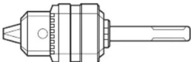
Drill chuck (Optional accessory)
•EY9HX400E
natural_image
Technical line drawing of a mechanical component with no visible text or symbolsUse with wood drill bit or metal drill bit with shank of 1.5 mm to 13 mm diameter.
Do not use the drill chuck in "Rotation with hammering mode" ( ). Use in "Rotation with hammering mode" may cause break of chuck or bit and result in injury.
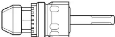
Hammer chuck (Optional accessory)
•EY9HX401E
natural_image
Technical line drawing of a mechanical connector or connector (no text or symbols)Use with concrete drill bit, wood drill bit or metal drill bit with straight shank of 2.5 mm to 13 mm diameter.
Do not use the hammer chuck with wood drill bit or metal drill bit in "Rotation with hammering mode" ( ↑ ). Use in "Rotation with hammering mode" may cause break of bit and result in injury.
If you need any assistance for more details regarding these accessories, ask your local service center.
VII. USAGE SUGGESTION
- If there isn't enough force pushing down on the bit, the tool may not be able to blow in hammering mode.
This is to prevent the hammering mode from operating with no load. Press down harder on the bit to engage the tool and cause it to blow.
- In winter or in other situations where the temperature of the unit is low (5°C (41°F) or below), the blow of the hammering mode may be weaker than normal at the beginning stage.
This is because the grease becomes stiffer in low temperatures, increasing friction.
If this should happen, operating hammering mode with no load for approximately 30 seconds and repeat this 3 times. This will restore its blowing power.
VIII. SPECIFICATIONS
MAIN UNIT
| Model | EY7840 | EY78A1 | ||
| Motor voltage | 14.4 V DC 14.4 V DC 18 V DC | |||
| Maximum drilling diameter | Concrete | 16.5 mmFor work that can be completed with one battery pack( 12.5 mm - 16.5 mm) | ||
| Steel | 13 mm | |||
| Wood 18 mm | ||||
| Speed at no load(RPM) 0~1000 rpm 0~1250 rpm | ||||
| Blows rate per minute(BPM) 3800 bpm 3800 bpm 4750 bpm | ||||
| Weight(with battery pack:EY9L44) | 2.45 kg 2.45 kg | - | ||
| Weight(with battery pack:EY9L45) | 2.45 kg 2.45 kg | - | ||
| Weight(with battery pack:EY9L50) | - | - | 2.6 | |
| Weight(with battery pack:EY9L51) | - | - | 2.6 | |
| Overall length | 249 mm | |||
| Noise,Vibration | See the included sheet | |||
GUIDELINE TABLE
- Select the torque for fastening screws with the clutch handle.
• Guide for the selection of torque
Depending on the job, adjustments are possible in five levels by approximately 1 N·m (10 kgf·cm) increments.
| Setting | Torque | Guide Depending on Material | ||||
| Concrete | Block | |||||
| (A) | (B) | (A) | (B) | |||
| Fastening Screws | 1 | Approximately 1.5 N·m (15 kgf·cm) | ● | |||
| 2 | Approximately 2.5 N·m (25 kgf·cm) | ● | ||||
| 3 | Approximately 3.4 N·m (35 kgf·cm) | ● | ● | ● | ||
| 4 | Approximately 4.4 N·m (45 kgf·cm) | ● | ● | ● | ||
| 5 | Approximately 5.4 N·m (55 kgf·cm) | ● | ||||
| Drilling Holes | (Drill Mark) | Approximately 14.4 V: 12.5 N·m (127 kgf·cm)18 V: 13.5 N·m (138 kgf·cm) | Drilling holes in wood and metal | |||
(A) For fastening screws into plastic anchor which requires dia. 6.0 mm prehole in the concrete.
(B) For directly fastening screws into concrete (like topcon) with dia. 3.5 mm prehole.
NOTE: This is only a rough guide. Required torque is different depending on the shape, material, and application of the screws.
Set according to the work environment of the site.
BATTERY PACK
| Model | EY9L41 EY | 9L42 EY9L44 | EY9L45 EY | 9L50 EY9L51 | ||
| Storage battery | Li-ion Battery | |||||
| Battery voltage | 14.4 V DC(3.6 V x 4 cells) | 14.4 V DC(3.6 V x 8 cells) | 18 V DC(3.6 V x 10 cells) | |||
BATTERY CHARGER
| Model | EY0L81 | |||||
| Electrical rating | See the rating plate on the bottom of the charger | |||||
| Weight | 0.93 kg | |||||
| Charging time | EY9L41 EY9L42 EY9L44 | EY9L45 EY9L50 EY9L51 | ||||
| Usable: 45 min | Usable: 30 min | Usable: 50 min | Usable: 65 min | Usable: 50 min | Usable: 65 min | |
| Full: 60 min | Full: 35 min | Full: 65 min | Full: 80 min | Full: 65 min | Full: 80 min | |
| Model | EY0L82 | |||||
| Electrical rating | See the rating plate on the bottom of the charger | |||||
| Weight | 0.93 kg | |||||
| Charging time | EY9L41 EY9L42 EY9L44 | EY9L45 EY9L50 EY9L51 | ||||
| Usable: 35 min | Usable: 30 min | Usable: 40 min | Usable: 50 min | Usable: 40 min | Usable: 55 min | |
| Full: 50 min | Full: 35 min | Full: 55 min | Full: 60 min | Full: 55 min | Full: 70 min | |
NOTE: This chart may include models that are not available in your area. Please refer to the latest general catalogue.
NOTE: For the dealer name and address, please see the included warranty card.
ONLY FOR U. K.
IX. ELECTRICAL PLUG INFORMATION
FOR YOUR SAFETY PLEASE READ THE FOLLOWING TEXT CAREFULLY
This appliance is supplied with a moulded three pin mains plug for your safety and convenience.
A 5 amp fuse is fitted in this plug.
Should the fuse need to be replaced please ensure that the replacement fuse has a rating of 5 amp and that it is approved by ASTA or BSI to BS1362.
Check for the ASTA mark 📍 or the BSI mark 🏠 on the body of the fuse.
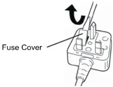
If the plug contains a removable fuse cover you must ensure that it is refitted when the fuse is replaced.
If you lose the fuse cover the plug must not be used until a replacement cover is obtained.
A replacement fuse cover can be purchased from your local Panasonic Dealer.
IF THE FITTED MOULDED PLUG IS UNSUITABLE FOR THE SOCKET OUTLET IN YOUR HOME THEN THE FUSE SHOULD BE REMOVED AND THE PLUG CUT OFF AND DISPOSED OF SAFELY.
THERE IS A DANGER OF SEVERE ELECTRICAL SHOCK IF THE CUT OFF PLUG IS INSERTED INTO ANY 13 AMP SOCKET.
If a new plug is to be fitted please observe the wiring code as shown below.
If in any doubt please consult a qualified electrician.
IMPORTANT: The wires in this mains lead are coloured in accordance with the following code:
Blue: Neutral
Brown: Live
As the colours of the wire in the mains lead of this appliance may not correspond with the coloured markings identifying the terminals in your plug, proceed as follows.
The wire which is coloured BLUE must be connected to the terminal in the plug which is marked with the letter N or coloured BLACK.
The wire which is coloured BROWN must be connected to the terminal in the plug which is marked with the letter L or coloured RED.
Under no circumstances should either of these wires be connected to the earth terminal of the three pin plug, marked with the letter E or the Earth Symbol.
How to replace the fuse: Open the fuse compartment with a screwdriver and replace the fuse and fuse cover if it is removable.
natural_image
Illustration of a device with a magnified view showing internal components (no text or symbols)natural_image
Illustration of a black electronic device with a light bulb and a fire extinguisher emitting exhaust smoke (no text or symbols)Schulterpolster
Betrieb
natural_image
Technical line drawing of a threaded fastener assembly (no text or symbols)Ausbau
natural_image
Pure mechanical diagram showing a spring-loaded component intersected by two diagonal lines (no text or symbols)[Akku]
natural_image
Technical line drawing of a mechanical drill bit (no text or symbols)Aufnahmekapazität:
natural_image
Technical line drawing of a mechanical component with no visible text or symbolsAdaptateur de mèche
Commutateur martelage/perforation REMARQUE:
natural_image
Line drawing of a handheld electric tool with handle and control panel (no text or symbols)Utilisation
natural_image
Technical line drawing of a mechanical screw assembly (no text or symbols)Retrait
natural_image
Pure mechanical diagram showing a spring with intersecting lines, no text or symbols present[Batterie]
natural_image
Technical line drawing of a mechanical component with no visible text or symbolsnatural_image
Technical line drawing of a mechanical component with threaded ends and a shaft (no text or symbols)Portabit
natural_image
Line drawing of a handheld electric tool with handle and control knob (no text or symbols)Cuscinetto spalla
Operazione
natural_image
Technical line drawing of a threaded fastener or screw assembly (no text or symbols)Rimozione
natural_image
Pure mechanical diagram showing a spring-loaded component intersected by two diagonal lines (no text or symbols)[Pacco batteria]
natural_image
Technical line drawing of a mechanical component with no visible text or symbolsnatural_image
Technical line drawing of a mechanical connector or connector (no text or symbols)natural_image
Line drawing of a handheld electric shaver with control panel (no text or symbols)Oververhitting (motor)
Knippert:
Oververhitting (accu)
natural_image
Illustration of a sunlight and a handheld device with light rays (no text or symbols)Schouderkussen
Bediening
natural_image
Technical line drawing of a threaded bolt assembly (no text or symbols)Legen
natural_image
Pure mechanical diagram showing a spring-loaded component intersected by two diagonal lines (no text or symbols)[Accu]
natural_image
Technical line drawing of a mechanical component with no visible text or symbolsnatural_image
Technical line drawing of a mechanical connector or connector (no text or symbols)Adaptador de broca
natural_image
Line drawing of a handheld electric tool with handle and control panel (no text or symbols)Disparador del control de velocided variable
natural_image
Illustration of a sun icon and a handheld device with light emission (no text or symbols)Forro de hombro
Uso
natural_image
Technical line drawing of a threaded fastener assembly (no text or symbols)Traslado
natural_image
Pure mechanical diagram of a coiled spring with intersecting lines (no text or symbols)[Bloque de pilas]
natural_image
Technical line drawing of a mechanical component with no visible text or symbolsnatural_image
Technical line drawing of a mechanical connector or connector (no text or symbols)Boradapter
natural_image
Line drawing of a handheld electric drill with handle and trigger (no text or symbols)Skulderpude
Betjening
natural_image
Technical line drawing of a threaded fastener assembly (no text or symbols)Aftagning
Hold i støvopsamlerens base for at tage den af.
Afmonter venligst, efter at borestøvet er fjernet fra borestøvsopsamleren.
Opbevaring
natural_image
Pure mechanical diagram showing a spring-loaded component intersected by two diagonal lines (no text or symbols)[Batteripakning]
natural_image
Technical line drawing of a mechanical component with no visible text or symbolsnatural_image
Technical line drawing of a mechanical connector or connector (no text or symbols)natural_image
Line drawing of a handheld electric drill bit with no visible text or symbolsnatural_image
Illustration of a portable flash unit and its corresponding electric gun (no text or symbols present)Användning
natural_image
Technical line drawing of a threaded fastener assembly (no text or symbols)Borttagning
natural_image
Pure mechanical diagram showing a spring with intersecting lines, no text or symbols present[Batteri]
natural_image
Illustration of a device with an open lid and internal components, showing directional arrows (no text or symbols)natural_image
Technical line drawing of a mechanical component with no visible text or symbolsnatural_image
Technical line drawing of a mechanical connector or connector (no text or symbols)Bitholderen
Forover/Revers bryter
Låst
natural_image
Line drawing of a handheld electric drill putter with handle and spout (no text or symbols)(2) Varsellampe for overoppheting


Av
(normalt arbeid)
Lyser:
Overoppheting (motor)
Blinker:
Overoppheting (batteri)
natural_image
Illustration of a sunlight and a handheld device with motion lines (no text or symbols)Bruk
natural_image
Technical line drawing of a mechanical screw assembly (no text or symbols)Fjerne
natural_image
Pure mechanical diagram showing a spring with intersecting lines, no text or symbols present[Batteripakke]
natural_image
Technical line drawing of a mechanical component with no visible text or symbolsnatural_image
Technical line drawing of a mechanical connector or connector (no text or symbols)Bitsi adapteri
natural_image
Line drawing of a handheld electric tool with handle and control panel (no text or symbols)Nopeudensäätökytkin
natural_image
Illustration of a sun icon and a handheld device with light rays (no text or symbols)Käyttö
natural_image
Technical line drawing of a threaded fastener or screw assembly (no text or symbols)Poisto
natural_image
Pure mechanical diagram showing a spring-loaded component intersected by two diagonal lines (no text or symbols)[Akku]
Akun oikea käyttö
natural_image
Technical line drawing of a mechanical component with no visible text or symbolsnatural_image
Technical line drawing of a mechanical component with no visible text or symbolsVIII. TEKNISET TIEDOT
PÄÄLAITE
EN. GR. FR. IT. ND. ES. DN. SW. NR. FN.
EY972078401 2012.09 Printed in China


- Index/Index/Index/Indice/Index/Indice/Indeks/Index/Indeks/Hakemisto
- GB
- Be sure to use the Pack cover
- For safe use
- D
- INTENDED USE
- ADDITIONAL SAFETY RULES
- WARNING:
- ASSEMBLY
- CAUTION:
- To insert the bit
- To remove the bit
- Bit adapter
- Attaching or Removing Battery Pack
- OPERATION
- Hammering/Drilling Switching Lever
- Clutch Torque Setting
- Variable Speed Control Trigger
- Control Panel
- LED light
- Overheat warning lamp
- Installing the Shoulder Strap
- Dust Collection Cup (EY9X005E) (Available as an optional accessory)
- Operation
- Removal
- Storage
- [Battery Pack]
- For Appropriate Use of Battery pack
- Battery Pack Life
- Battery Recycling
- ATTENTION:
- [Battery Charger]
- Charging
- Cautions
- Li-ion Battery Pack
- NOTE:
- Battery charger
- Information for Users on Collection and Disposal of Old Equipment and used Batteries
- For business users in the European Union
- [Information on Disposal in other Countries outside the European Union]
- Note for the battery symbol (bottom two symbol examples):
- MAINTENANCE
- ACCESSORIES
- USAGE SUGGESTION
- SPECIFICATIONS
- GUIDELINE TABLE
- ONLY FOR U. K.
- ELECTRICAL PLUG INFORMATION
- FOR YOUR SAFETY PLEASE READ THE FOLLOWING TEXT CAREFULLY
- Betrieb
- Ausbau
- [Akku]
- Adaptateur de mèche
- Commutateur martelage/perforation REMARQUE:
- Utilisation
- Retrait
- [Batterie]
- Portabit
- Operazione
- Rimozione
- [Pacco batteria]
- Bediening
- Legen
- [Accu]
- Adaptador de broca
- Disparador del control de velocided variable
- Uso
- Traslado
- [Bloque de pilas]
- Boradapter
- Betjening
- Aftagning
- Opbevaring
- [Batteripakning]
- Användning
- Borttagning
- [Batteri]
- Bitholderen
- Forover/Revers bryter
- Varsellampe for overoppheting
- Bruk
- Fjerne
- [Batteripakke]
- Bitsi adapteri
- Nopeudensäätökytkin
- Käyttö
- Poisto
- Akun oikea käyttö
- TEKNISET TIEDOT
Brand : PANASONIC
Model : EY78A1
Category : Screwdriver