BC 30 - Dashboard camera GARMIN - Free user manual and instructions
Find the device manual for free BC 30 GARMIN in PDF.

User questions about BC 30 GARMIN
0 question about this device. Answer the ones you know or ask your own.
Ask a new question about this device
Download the instructions for your Dashboard camera in PDF format for free! Find your manual BC 30 - GARMIN and take your electronic device back in hand. On this page are published all the documents necessary for the use of your device. BC 30 by GARMIN.
USER MANUAL BC 30 GARMIN
BC™ 30 Wireless Backup Camera
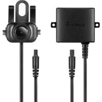
natural_image
Illustration of a camera lens on a road with green grass and a curved road in the background (no text or symbols)Installation Instructions.... 2
Instructions d'installation....5
Gamin ^® and the Garmin logo are trademarks of Garmin Ltd. or its subsidiaries, registered in the USA and other countries. BC ^™ is a trademark of Garmin Ltd. or its subsidiaries. These trademarks may not be used without the express permission of Garmin.
BC™ 30 Wireless Backup Camera Installation Instructions
Introduction
WARNING
See the Important Safety and Product Information guide in the product box for product warnings and other important information.
Garmin ^® strongly recommends having an experienced installer with the proper knowledge of electrical systems install the device. Incorrectly wiring the power cable can result in damage to the vehicle or the battery and can cause bodily injury.
When connecting the power cable, do not remove the in-line fuse holder. To prevent the possibility of injury or product damage caused by fire or overheating, the appropriate fuse must be in place as indicated in the product specifications. In addition, connecting the power cable without the appropriate fuse in place will void the product warranty.
CAUTION
Always wear safety goggles, ear protection, and a dust mask when drilling, cutting, or sanding.
NOTICE
When drilling or cutting, always check what is on the opposite side of the surface.
These installation instructions do not apply to a specific vehicle type, and are meant as a guide when installing this product on your vehicle. For questions specific to your vehicle, you should contact the vehicle manufacturer.
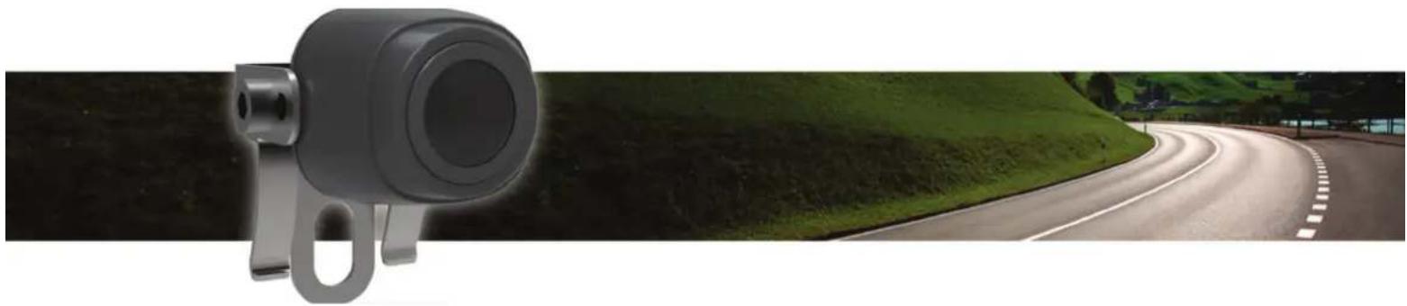
Device Overview
text_image
Diagram showing four labeled parts of a mechanical device with numbered annotationsItem Description
| 1 | BCTM 30 receiver cableThe GPS device must be powered through this cable to communicate with the camera. |
| 2 | Transmitter |
| 3 | Camera |
| 4 | Camera mounting bracket |
Tools Needed
- Drill and 9.09 mm, or size T (0.36 in.) drill bit
• #2 Phillips screwdriver - Screws, bolts, or cable ties (to secure the transmitter)
- Solderless wire-splice connector or solder and heat-shrink tubing
• RV sealant (optional)
Installation
Installing the Receiver
Before you can install the BC 30 receiver cable, you must update your GPS device to the most recent software version. Your GPS device may not be compatible with the BC 30 camera
without the most recent software. See your GPS device owner's manual or go to garmin.com/express for more information about updating your GPS device.
The wireless camera receiver is built into BC 30 receiver cable included with your wireless backup camera.
Use the BC 30 receiver cable included with your BC 30 camera to connect your GPS device to vehicle power. See the owner's manual for your GPS device for more information about connecting the device to vehicle power.
NOTE: The BC 30 receiver cable includes a traffic receiver. If your GPS device includes lifetime traffic, the traffic features continue to function while using the BC 30 receiver cable.
Camera Mounting Considerations
When selecting a location to mount the camera, observe these considerations.
- You should test a mounting location before you permanently mount the camera.
- Installing the camera higher on the back of the vehicle provides a better viewing angle.
- The included bracket can be clipped onto a license plate or other similar surface, or it can be fastened to the back of the vehicle using the included self-tapping, panhead screws.
Transmitter Location and Wiring Considerations
NOTICE
The transmitter is not intended to be held or worn on your body while it is in use.
When selecting a location to install the wireless transmitter, observe these considerations.
- You should test a proposed installation location before you permanently install the transmitter.
- Some vehicles do not provide constant minimum voltage to the reverse lamps. You should use an automotive relay when connecting the transmitter and camera to a power source that does not provide constant voltage.
- Although the transmitter can reliably transmit the video signal over approximately 13.5m (45 ft.), the location of the transmitter can affect this range.
• The closer you install the transmitter to the receiver, the more reliable the signal.
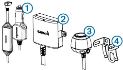
• The transmitter provides the best signal when either flat surface ① is pointing toward the receiver.
text_image
① ① ②- Dense metal or appliances ② in the path of the transmitter greatly reduce the transmission distance.
- The fewer solid objects that exist between the path of the transmitter and the device, the more reliable the signal.
- If the distance between the camera and the transmitter exceeds the length of the included cable, additional extension cables can be used. A 15 m (50 ft.) extension cable can be purchased, and more than one extension cable can be installed. See your Garmin dealer or go to www.garmin.com for more information.
- The fuse holder located near the transmitter is not waterproof. Installing the fuse holder in a location that is exposed to the elements is not recommended.
- The connector between the camera and the transmitter is not waterproof. If you make this connection in a location exposed to the elements, you must make sure that the connection is waterproof.
- If you are installing the camera on a boat trailer or other location that may be exposed to water, you must waterproof all wiring connections and the fuse holder in the transmitter cable.
Testing the Camera and Transmitter Location
1 Temporarily secure the camera in the preferred mounting location.
2 Temporarily place the transmitter in the preferred installation location, and connect it to power and to the camera.
TIP: If you do not want to splice into the wiring of your vehicle for this test, you can connect the transmitter and camera to a 12 Vdc battery.
3 Test the transmitter for correct operation by applying power to the GPS device using the BC 30 receiver cable.
If you do not see video on the GPS device at the preferred installation location, move the transmitter to another location and test it again.
4 Repeat steps 2–3 until the transmitter operates correctly.
5 Test the camera view by observing the video on the device.
6 If the camera does not provide the optimal view for your vehicle, move it to another location and test it again.
7 Repeat steps 5–6 until the camera mounting location provides the optimal view for your vehicle.
TIP: Make note of which direction is up when you are testing the camera view to ensure correct permanent installation.
Mounting the Camera
Before you permanently mount the camera, you should test the mounting location for the optimal view for your vehicle (Testing the Camera and Transmitter Location).
If you have already connected the camera to the bracket, you must first disassemble it.
1 Place the bracket ① in the mounting location.
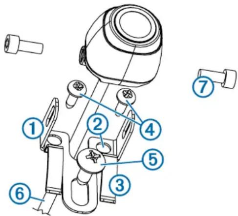
text_image
Technical diagram of a mechanical device with numbered parts for identification2 Select an option:
- If you are mounting the bracket directly on the surface of your vehicle, mark the locations of the two holes on the bracket ②.
- If you are installing the bracket on a license plate, remove one of the license plate screws and clip the bracket in place so the hole on the bracket ③ lines up with the hole on the license plate.
3 Secure the bracket to the vehicle using either the included self-tapping screws ④ or the license-plate screw you removed in step 2 ⑤.
4 Place the camera in the bracket, and determine the best place for the camera cable ⑥ to enter the vehicle.
5 Using an appropriate drill bit, drill a hole for the camera cable to enter the vehicle.
6 Feed the camera cable through the hole and route it to the transmitter location.
15 m (50 ft.) extension cables can be purchased separately if needed.
7 Secure the camera in the bracket using the included hex bolts ⑦.
8 Adjust the angle of the camera and tighten the hex bolts using the included hex key.
9 Apply RV sealant around the cable where it enters the vehicle (optional).
Installing the Transmitter
Before you permanently install the transmitter, you must test the installation location for correct operation (Testing the Camera and Transmitter Location).
1 Secure the transmitter to the installation location using hardware appropriate for the location, such as screws, bolts, or cable ties.
The fuse holder located near the transmitter is not waterproof. Installing the fuse holder in a location that is exposed to the elements is not recommended.
2 Connect the camera and transmitter cables.
The connector between the camera and the transmitter is not waterproof. If you make this connection in a location exposed to the elements, you must make sure that the connection is waterproof.
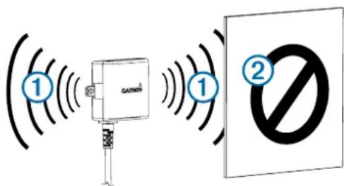
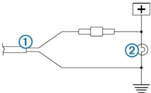
3 Connect the power cable ① from the transmitter to a 12–24 VDC power source, preferably a reverse lamp ②, using a solderless wire-splice connector (not included).
text_image
Electrical circuit diagram with labeled components and connections, including a power source, switch, resistor, and ground connection.NOTE: Connecting the transmitter to an always-on 12-24 VDC source (such as a running lamp) instead of a reverse lamp requires you to manually switch power to the transmitter. The transmitter may drain your vehicle battery if it is left on.
4 If you did not use a solderless wire-splice connector, solder and heat-shrink the electrical connections to protect them from the elements.
Appendix
Multiple Cameras
You can pair up to four wireless cameras with the BC 30 receiver cable. For example, you can pair one backup camera installed on your vehicle and a second backup camera installed on a trailer. See the BC 30 Wireless Backup Camera Owner's Manual for information about pairing multiple cameras.
Getting the Owner's Manual
You can get the most recent owner's manual from the web.
1 Go to garmin.com/manuals/BC30.
2 View or download the full owner's manual in your preferred format.
Specifications
| Camera and transmitter input voltage | From 9 to 28 Vdc |
| Transmitter fuse 500 mA, fast-blow | |
| Camera and transmitter current usage | 150 mA at 12 Vdc |
| Camera and transmitter waterproof rating | IEC 60529 IPX7* |
| Camera temperature range From -40° to 85°C (from -40° to 185°F) | |
| Transmitter and receiver cable temperature range | From -20° to 70°C (from -4° to 158°F) |
| Receiver cable input voltage From 10 to 24 V | |
| Receiver cable fuse 2 A, 250 V | |
*The device withstands incidental exposure to water of up to 1 m for up to 30 min. For more information, go to www.garmin.com /waterrating.
text_image
Diagram showing four labeled parts of a mechanical device with numbered annotationsElément Description
text_image
Technical diagram of a mechanical device with numbered parts for identificationtext_image
Electrical circuit diagram with labeled components and connections, including a plus and minus symbolstext_image
① GARMIN® ② ③ ④text_image
Technical diagram of a mechanical device with numbered parts for identificationtext_image
Electrical circuit diagram with labeled components and connection pointstext_image
Diagram showing four labeled parts of a hairdryer device with numbered callouts for identification.text_image
Technical diagram of a mechanical device with numbered parts for identificationtext_image
Electrical circuit diagram with labeled components and connection pointstext_image
Diagram showing four labeled parts of a mechanical device with numbered annotationstext_image
Technical diagram of a mechanical device with numbered parts for identificationtext_image
Electrical circuit diagram with labeled components and connections, including a plus and minus symbolstext_image
① GARMIN® ② ③ ④Item Descrição
text_image
Technical diagram of a mechanical device with numbered parts for identificationtext_image
Electrical circuit diagram with labeled components and connection pointstext_image
① GARMIN® ② ③ ④text_image
Technical diagram of a mechanical device with numbered parts for identificationtext_image
Electrical circuit diagram with labeled components and connection pointstext_image
① GARMIN ② ③ ④Punkt Beskrivelse
text_image
Technical diagram of a mechanical device with numbered parts labeled 1 through 72 Vælg en funktion:
text_image
Electrical circuit diagram with labeled components and connection pointstext_image
① GARMIN ② ③ ④Kohde Kuvaus
text_image
Technical diagram of a mechanical device with numbered parts labeled 1 through 7text_image
Electrical circuit diagram with labeled components and connections, including a power source, switch, resistor, and ground connection.text_image
Diagram showing four labeled parts of a hairdryer device with numbered callouts for identification.Element Beskrivelse
| 1 | BC 30 mottakerkabelGPS-enheten må forsynes strøm via denne kabelen for å kunne kommunisere med kameraet. |
| 2 | Sender |
| 3 | Kamera |
| 4 | Monteringsbrakett for kamera |
Nødvendige verktøy
text_image
Technical diagram of a mechanical device with numbered parts for identification2 Velg et alternativ:
- Hvis du monterer braketten direkte på overflaten av kjøretøyet, merker du av plasseringen for de to hullene på braketten②.
- Hvis du installerer braketten på et nummerskilt, fjerner du en av skruene på nummerskiltet og klipser braketten på plass slik at hullet på braketten③ er på linje med hullet på nummerskiltet.
text_image
Electrical circuit diagram with labeled components and connections, including a power source, switch, resistor, and ground connection.text_image
① GARMIN ② ③ ④Objekt Beskrivning
text_image
Technical diagram of a mechanical device with numbered parts labeled 1 through 7text_image
Electrical circuit diagram with labeled components and connections, including a power source, switch, resistor, and ground connection.text_image
Diagram showing four labeled parts of a mechanical device with numbered annotationsElement Opis
text_image
Technical diagram of a mechanical device with numbered parts for identification2 Wybierz opcję: