
RT602 - Car radio MTX Audio - Free user manual and instructions
Find the device manual for free RT602 MTX Audio in PDF.
| Product Type | 2-Channel Class-AB Amplifier |
| Brand | MTX Audio |
| Model | RT602 |
| Category | Car Audio / Amplifier |
| Dimensions (L × W × H) | 310 mm × 180 mm × 55 mm |
| Weight | Approx. 2 kg |
| Power Supply | 12 V DC (vehicle battery) |
| Output Power (CEA2006) | 2 × 90 W RMS @ 2 ohms, 2 × 60 W RMS @ 4 ohms, 1 × 180 W RMS bridged @ 4 ohms |
| Frequency Response | 20 Hz - 30 kHz (±1 dB) |
| Signal-to-Noise Ratio | >80 dB (1 watt) |
| Distortion (THD+N) | ≤1% |
| Active Filter | High-pass (HPF) and Low-pass (LPF) 12 dB/oct, adjustable from 40 Hz to 400 Hz |
| RCA Input Sensitivity | 100 mV to 6 V |
| Inputs | Low level RCA, high level (HLI with included adapters) |
| Line Output | Line out for chaining another amplifier |
| Minimum Impedance | 2 ohms stereo, 4 ohms bridged |
| Protection | Thermal and short circuit (blinking LED) |
| Fuses | Internal, replace with same value fuse |
| Maintenance and Cleaning | Clean with a dry cloth. Check and tighten connections periodically. |
| Safety | Disconnect battery before installation. Use a fuse near the battery. Observe impedances. |
| Spare Parts and Repairability | Replacement fuses. High-level adapters included. Contact a professional installer for any repairs. |
| General Information | High-performance amplifier for car audio system. Brand: MTX Audio, model RT602. |
Frequently Asked Questions - RT602 MTX Audio
User questions about RT602 MTX Audio
0 question about this device. Answer the ones you know or ask your own.
Ask a new question about this device
Download the instructions for your Car radio in PDF format for free! Find your manual RT602 - MTX Audio and take your electronic device back in hand. On this page are published all the documents necessary for the use of your device. RT602 by MTX Audio.
USER MANUAL RT602 MTX Audio
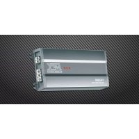
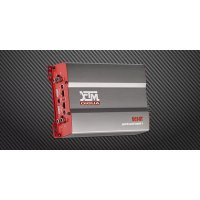
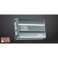
2-Channel Class-AB Power Amplifier
540W MAX
Designed by MTX in the USA
www.mtxaudio.com
www.mtxaudio.eu
Introduction
Thank you for purchasing an MTX Audio Hi-Performance amplifier. Proper installation matched with MTX speakers and subwoofoers provide superior sound and performance for endless hours of waking the neighbors, slam-min' your friends or flat out stomping wanna-be players. Congrats and enjoy the ultimate audio experience with MTX!
Specifications :
2-Channel Class-AB Amplifier
- CEA2006 certified Power Output :
- 90 watts RMS x 2-channel at 2 ohm and THD+N ≤1%
- 60 watts RMS x 2-channel at 4 ohm and THD+N ≤1%
- 180 watts RMS x 1-channel at 4 ohm and THD+N ≤1%
Crossover:
- High pass 12dB/act variable from 40Hz to 400Hz
-
Low pass 12dB/oct variable from 40Hz to 400Hz
-
Signal-to-Noise Ratio (1 watt): >80dB
- THD+Noise (Distortion) (1 watt): ≤ 1%
Frequency Response (± 1dB) : 20Hz - 30000Hz
Maximum Input Signal : 6V
Maximum Sensitivity: 100mV - Dimensions : 310mm x 180mm x 55mm
High level inputs
Control Panel
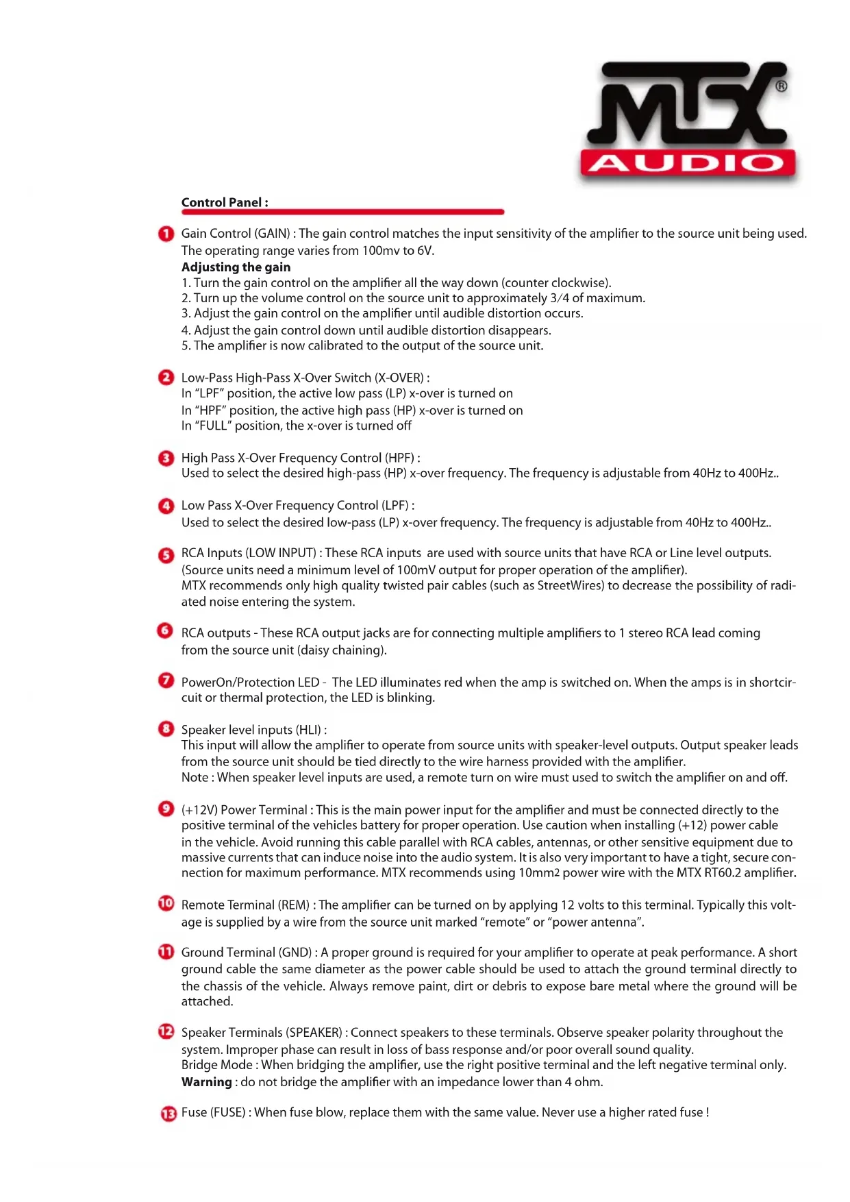
Control Panel :
Gain Control (GAIN): The gain control matches the input sensitivity of the amplifier to the source unit being used. The operating range varies from 100mv to 6V.
Adjusting the gain
- Turn the gain control on the amplifier all the way down (counter clockwise).
- Turn up the volume control on the source unit to approximately 3/4 of maximum.
- Adjust the gain control on the amplifier until audible distortion occurs.
- Adjust the gain control down until audible distortion disappears.
- The amplifier is now calibrated to the output of the source unit.
Low-Pass High-Pass X-Over Switch (X-OVER):
In "LPF" position, the active low pass (LP) x-over is turned on In "HPF" position, the active high pass (HP) x-over is turned on In "FULL" position, the x-over is turned off
3 High Pass X-Over Frequency Control (HPF):
Used to select the desired high-pass (HP) x-over frequency. The frequency is adjustable from 40Hz to 400Hz..
4 Low Pass X-Over Frequency Control (LPF) :
Used to select the desired low-pass (LP) x-over frequency. The frequency is adjustable from 40Hz to 400Hz..
RCA Inputs (LOW INPUT): These RCA inputs are used with source units that have RCA or Line level outputs.
(Source units need a minimum level of 100mV output for proper operation of the amplifier).
MTX recommends only high quality twisted pair cables (such as StreetWires) to decrease the possibility of radiated noise entering the system.
RCA outputs - These RCA output jacks are for connecting multiple amplifiers to 1 stereo RCA lead coming from the source unit (daisy chaining).
PowerOn/Protection LED - The LED illuminates red when the amp is switched on. When the amps is in short circuit or thermal protection, the LED is blinking.
8 Speaker level inputs (HLI):
This input will allow the amplifier to operate from source units with speaker-level outputs. Output speaker leads from the source unit should be tied directly to the wire harness provided with the amplifier.
Note : When speaker level inputs are used, a remote turn on wire must used to switch the amplifier on and off.
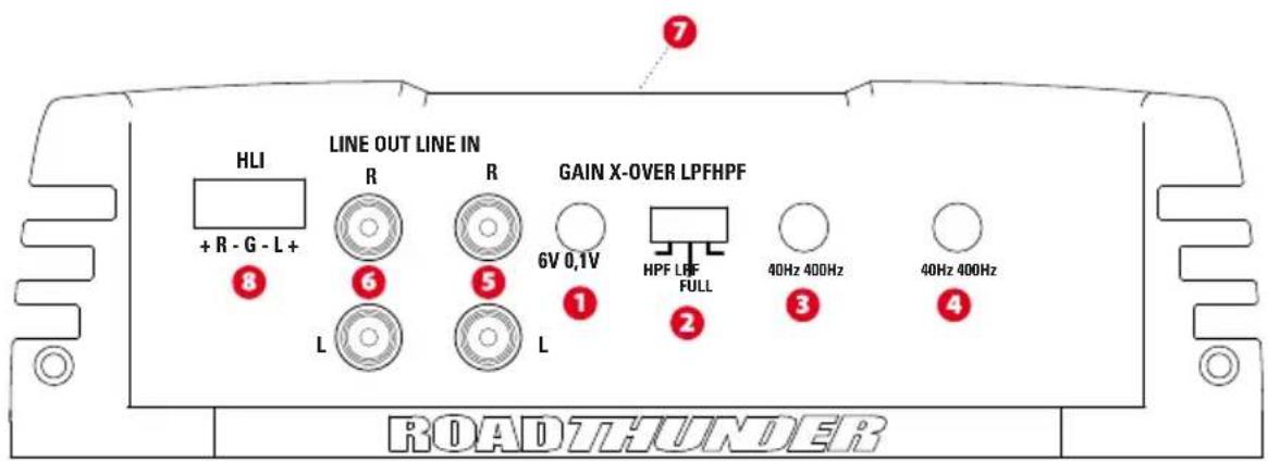
(+12V) Power Terminal : This is the main power input for the amplifier and must be connected directly to the positive terminal of the vehicles battery for proper operation. Use caution when installing (+12) power cable in the vehicle. Avoid running this cable parallel with RCA cables, antennas, or other sensitive equipment due to massive currents that can induce noise into the audio system. It is also very important to have a tight, secure connection for maximum performance. MTX recommends using 10mm2 power wire with the MTX RT60.2 amplifier.
Remote Terminal (REM) : The amplifier can be turned on by applying 12 volts to this terminal. Typically this voltage is supplied by a wire from the source unit marked "remote" or "power antenna".
Ground Terminal (GND): A proper ground is required for your amplifier to operate at peak performance. A short ground cable the same diameter as the power cable should be used to attach the ground terminal directly to the chassis of the vehicle. Always remove paint, dirt or debris to expose bare metal where the ground will be attached.
12 Speaker Terminals (SPEAKER): Connect speakers to these terminals. Observe speaker polarity throughout the system. Improper phase can result in loss of bass response and/or poor overall sound quality.
Bridge Mode : When bridging the amplifier, use the right positive terminal and the left negative terminal only.
Warning : do not bridge the amplifier with an impedance lower than 4 ohm.
Fuse (FUSE) : When fuse blow, replace them with the same value. Never use a higher rated fuse!
Owner's Manual - RT60.2
Installation & Mounting
MTX recommends your new Thunder amplifier be installed by an Authorized MTX retailer. Any deviation from specified installation instructions can cause serious damage to the amplifier, speakers and/or vehicles electrical system. Damage caused from improper installation is NOT covered under warranty. Please verify all connections prior to system turn on!
-
Disconnect the vehicle's negative battery cable.
-
Determine the mounting place for your MTX amplifier. Keep in mind there should be sufficient air flow for proper cooling. Mark the mounting holes from the amplifier to be drilled. Before drilling make sure all vehicle wires, gas lines, brake lines and gas tank are clear and will not interfere with installation. Drill the desired holes and mount the MTX amplifier.
-
Install a positive (+) power cable from the vehicle's battery through the firewall using a grommet or firewall bushing to avoid cable damage from sharp edges of the firewall. Run the cable through the interior of the vehicle and connect it to the amplifier's (+12V) terminal. Do Not connect to the battery at this time. Note : Use only proper gauge wire for both positive and negative connections.
-
Install a circuit breaker or fuse within 20cm of the battery. This effectively lowers the risk of severe damage to you or your vehicle in case of a short circuit or accident. Make sure the circuit breaker is switched off or the fuse is taken out of the fuse holder until all connections are made. Now connect your positive power cable to the positive battery terminal of the battery.
-
Grounding - Locate a proper ground point on the vehicle's chassis and remove all paint, dirt or debris to reveal a bare metal surface. Attach the ground wire to that contact point. Connect the opposite end of the ground wire to the (GND) terminal on the MTX amplifier.
-
Connect a Remote Turn-on wire from the source unit to the MTX amplifier's (REM) terminal. If the source unit does not have a dedicated Remote Turn-on lead, you may connect to the source unit's Power Antenna lead.
-
Connecting signal cables to the amplifier : There are two ways to supply the signal to your MTX amp.
-
To get maximum performance, we suggest connecting a high quality RCA to the corresponding outputs at the source unit and inputs of the amplifier.
-
If a source unit is being used without RCA outputs, use the included high-level amplifier's speaker terminals using the right gauge speaker wire.
-
Connect your speakers to your MTX amplifier's speaker terminals using the right gauge speaker wire. Bridged channels can drive a 4 ohm minimum load for max power.
-
Double check all previous installation steps, in particular, wiring and component connections. Once verified, reconnect the vehicle's negative battery cable, turn the circuit breaker on or place the fuse in the fuse holder.
Note : Gain Levels on the amplifier should be turned all the way down (counter clockwise) before proceeding with adjustments.
Troubleshooting
Problem
Cause
Solution
No LED indication No +12V at remote connection Supply +12V to terminal
No +12V at Power connection Supply +12V to terminal
Insuffcient ground connection Verify ground connection
Blown power fuse Replace fuse
Power LED on, no output Volume on source unit off Increase volume on source unit
Speaker connections not made Make speaker connections
Gain control on amplifier off Turn up gain
Signal processing units off Apply power to signal processor
All speakers blown Replace speakers
Output distorted Head unit volume set too high Lower head unit volume
Amplifier gain set too high
Lower amplifier gain
Balance reversed
RCA inputs reversed
Speakers wired L + R reversed
Reverse RCA input
Wire speakers with correct orientation
Bass is weak
Not using MTX woofers
Speakers wired out of phase
Buy MTX woofers
Wire speakers with correct phase
Blowing fuses
Amplifier defective
Excessive output levels
Return for service
Lower the volume
Introduction:
MTX woofers no son usados
Compra woofers MTX
Fusibles danados Amplificador defectuoso
Owner's Manual - RT60.2
Owner's Manual - RT60.2
YcTaHOBKa M MoHTaK
MTX peKOMeHdyeT yCTaHaBnBaTb BaW HObIy ycNITeB RoadTHUNDER aBTOp3nIOBaHbIM npedctaBtTeEM MTX. ManeiJee OTKIOHeHne OT cneuaJIbHbIX INCTpyKcI N O yCTaHOBe MoKe T HaHeCTn cepbe3Hb I BpeYcIJIteIIO, DNHAMIKAM N/IIIN 3NeKTPnuecko CnCTeMe aBTOMO6nla. UseP6, npuHHHbI npHepaBnBHOYCTaHOBKe, HE nOKpbIbaETcra rapaHTnei. PoxanyIcTa, pOBepbTe BCE coeHNHeHna neped BKIOUeHEm cnCTeMb!
- OToeHNHnTe OTPuataeIbHbI Ka6ebIaKKymyIaTopa ABTomO6nIa.
- OnpeJeNTecb C MeCTOM MOHTaKa BaWero ycNITeMa MTX. IMeTe BvNDy, YTO DnHaJIeXaIero OxJAKHeHn HEO6xOIM DOCTaOTHyB NOTOK BO3dyxa. OTMeTbTe MecTa CBepHnA OTBepCTn Dn MaMTaKa. IpePeCBepHnEM y6eINTecb, YTO BCE deta ABtOMo6NJra HaxODrCA B uNCTOTE n He NOMEwAOT yCTAHOBKe. IpocCBepNTe OTBepCTn r UcTAHOBnTE yCNITeB.
- PpOBeIte npOBd nonIOcoBOro nHTAHn O T AKKymyIaTopa yepe3 noKapHy o neperopodky, nCnoJIb3y yNtHOHuee KOnbU O nn pezHHOBvY Btynkdy IIN 36exHa NOBpeXJHeN IpOBOda OCTpbIM KpaAMn NOKAPHOI pepEROpDkn. PpOBeIte npOBd uepe3 cAnOH aBTOMo6nIg N IOcOeHNHte K pa3bemy +12V ycInnTeJ. He nOcOeHNHITecb K AKKymyIaTopy B 3OT MOMENT.
PpmeHHe: nCnObl3yIe ToIbKO npOBoDky nOxOJaIero pa3Mepa, KaK IJIra PJIIOca, TaK I DJIra MInHyCa.
- UctahOBHTe npedoxpaHntel Ha pacCToAHn 20cm OTAKKymIaTopa. 3TO NOMOKeT 3aUHTb ABTomO6nlb npu 3AmbKaHn. He BkLIOaHTe BbIKHOaTeH n He yCTaHaBnBaIte npdeoxpaHntel, noka He 6ydy T BblONHeHb BCE NOcOeHNHeHn. Tepe b noDKIOUHTe pOBOD nIOOCOBOr OITaHn K NIOCOBOK KJEMMe AKKMyIaTopa.
5.3a3emnene -Bb6epnte noxdoae meTo nla 3a3emnna Ha waccn BaWero aBTOMO6nna n 3aunctne erO. PpIIOXNTe npOBOD 3a3emnna K TOUKe KOHTAKTa N NOCDoeHNTe npOTUBONIOxHbIK KOHeC npOBOna 3a3emnna K pa3bemy GND ha ycInnte MTX.
6.Подсоeннite ДИСТаHиОнньиnpOBOD nITaHЯ OT nICTOHnKa CnHaJa K pa3bemy Remote ha yCunIHTene MTX.EcIny uNCTOuHnKa nITaHЯ HET BbIBOdaДИСТaHиOHHORO npOBoDa,Bbl moKTe nOДсоeHnHTbcr K TeJIeCKONnuecko aHTehHe C 3NeKTPonpNBODom.
7.Подсоeннене сгнаньхкбеник усинтелю:Естдba cnoocob ha npabntb cnrhan k ycninntelIO MTX. ⅡЯ МakcmaJIbHO KaueCTBeHHOH 3KcnnyaatauMblпpeNaRaEM NOcdoeHHTb BbicOKokaueCTBeHHBI RCA K COOTBETCTBYUOM pa3beMaM Ha nctOCHNIke CgHnlaHa Ha ycInNTene.
- Ecni nctouHn CnHana nCnOJb3yeTc 6e3 pa3beMOB RCA, nCnOJb3yIe BblCOKOpyOBHeBbI pa3beMbI dHAMKOB C npoBOdom nOxDxOJaero pa3mepa.
8.ПрсоeINHInTeДиHamNKK K pa3bEmOB ДЯДиHamNKOB Ha yCnInTeMe MTX,Испь3у npOBOD nOxOJaero pa3mepa.DЯ MaKcIMaJIbHOI MOUHOCTH MocTOBbl MOry Pa6OtaTb npi MmHImaJIbHOH Harpy3ke B 4 OMa.
- NpeepnpoeBpTe Bce npdebyuue warr no yctahOBke, oc6eHNO npoBOa n coeHNHeHn. Iocne npobepkn 3aHOBO npOcEOHNHTe OTPuaTeIbHbIKabeKKyMylrTopa, BKIOHTe BblKIOUaTeIb INN yCTAHOBtenepeOxpaHntelb.
PpmeHHe: PeryIaTOpbl yCnIeHnHa ycIInTeJx HxKHO NOBepHyTb do npedeJa (npotuBa cacoBoi ctpenKn) nepe npoDOnJXeHnem HacToPiKn.
Yctpaehne HncnpabHocte
PpO6Iema
PpUHa
PeweHne
Het nHdkaTopo OTCyTCTByET+12B npu ydaJIeHHOM IOnkIIOHTe +12B K TePMHaNany
LED noKJIIOHnI
OcyTCTByeT +12B B pa3bEme nHTaHn IopKnIOuTe +12B K TepMNHaN
HeIOCTaTOHoe 3aEMnEHHne IPOBepbTe 3aEMnEHHe
CropaHne npedoxpaHnte 3amEnTe npedoxpaHnteB
LED BKNIOUeH, HET BbIKIOUeH 3ByK NCTOUYHka CnHaJa IIO6aBBTe rPOMKOCTb Ha NCTOUYHKe BHeuHrero CnHaJa CnHaJa
He npoklioehebl nHaMnKIpokkIouHte HnHaMnK
BbIKIOueH KOHTpOJIb ycINJIeHn BKnIOUHTe erO cHOBA
BbIKIIOueHb6IOKo 6Opa6OTKn CnHaJIOB IOnkIIOUHTe 6IOKo 6pa6OTKn
CnHaIOB
Cropenni dHnAmnKu
3aMeHnTe nnHaMnKn
NckaxkEHNrHaHa YctahOBHea CInuKOM 60nbua rPOMKOCTb Y6aBbTe 3ByK rONOBHOrO yCTpOcTBA
BbIXOe TONOBHORO yCTPOIcTBA
YcTaHOBNeHO CnIMKOM 60Jbwoe ycJIeHne YMeHbWnte ycJIeHne
Ha ycnilntene
Hapyen 6aanaHc HnpabnblHoe noKIOueHne nnHaMKOB L+R POnkIOUHTe nnHaMKn npabnlbHO
RCA BBOBII npepyTaHbI
TomenrTe RCA BBObl
Cna6bI 6ac
HeBepHae a3a dHaMkoB
POncoeunHte DnHaMkn C BepHo
IcnoJIb3yIOCTByΦepbIpyrOΦnPmbl
Kynite Byfepebl MTX
CropaHne
Upe3mepHbI ypoBeHb BbIXoHOrO cnHaHa
Y6aBBTe 3ByK
PpeOxpaHnteIeHn
Deefekt ycnnteia
BepHnte Ha peMOHT
Esipuhe
Wire speakers with correct orientation
(lewy z sprawym)
MTX is proud to be an American Audio Company.

MTX is a proud member of Mitek Corp high quality consumer audio product lines.

MiTek
Corporation

AUDIO
STREETWIRES
Designed and Engineered by Mitek in Phoenix - AZ, USA
Assembled in PRC
© 2011 Mitek. All rights reserved
MTX, COUSTIC, XTANT, STREETWIREs and RoadTHUNDER
are registered trademarks of Mitek
Due to continual product development, all
specifications are subject to change without notice
Mitek-MTX
4545 East Baseline Rd. Phoenix, AZ 85042, USA

Brand : MTX Audio
Model : RT602
Category : Car radio