
X3-17-DK - Car radio MTX Audio - Free user manual and instructions
Find the device manual for free X3-17-DK MTX Audio in PDF.

| Brand | MTX Audio |
| Model | X3-17-DK |
| Product Type | Dash Kit (installation kit for aftermarket head unit) |
| Compatible Vehicles | Can-Am Maverick X3 (2017-2021): Turbo, Turbo R, X-DS, X-RS, X-MR, X-RC, DS, RS, and RR variants |
| Designed For | MTX Audio AWMC3 Bluetooth all-weather head unit |
| Included Items | Dash kit, compression plate, (2) compression plate screws, (4) shroud screws, (2) source unit screws |
| Installation Tools Required | 1" hole saw, Torx T8 and T20 screwdrivers, drill with 1/8" drill bit |
| Warranty | 2-year limited warranty (from date of purchase by end user) |
| Material | ABS plastic, black finish |
| Mounting Type | Flush-mount, screw-in (replaces factory center dash tray) |
| Special Features | OEM fit, compression plate for secure radio mounting, included wiring pass-through |
| Safety | Disconnect battery before installation; fuse power wire at battery connection |
| Maintenance | Wipe with damp cloth; avoid harsh chemicals |
| Compliance | Designed and engineered in the USA |
Frequently Asked Questions - X3-17-DK MTX Audio
User questions about X3-17-DK MTX Audio
0 question about this device. Answer the ones you know or ask your own.
Ask a new question about this device
Download the instructions for your Car radio in PDF format for free! Find your manual X3-17-DK - MTX Audio and take your electronic device back in hand. On this page are published all the documents necessary for the use of your device. X3-17-DK by MTX Audio.
USER MANUAL X3-17-DK MTX Audio
natural_image
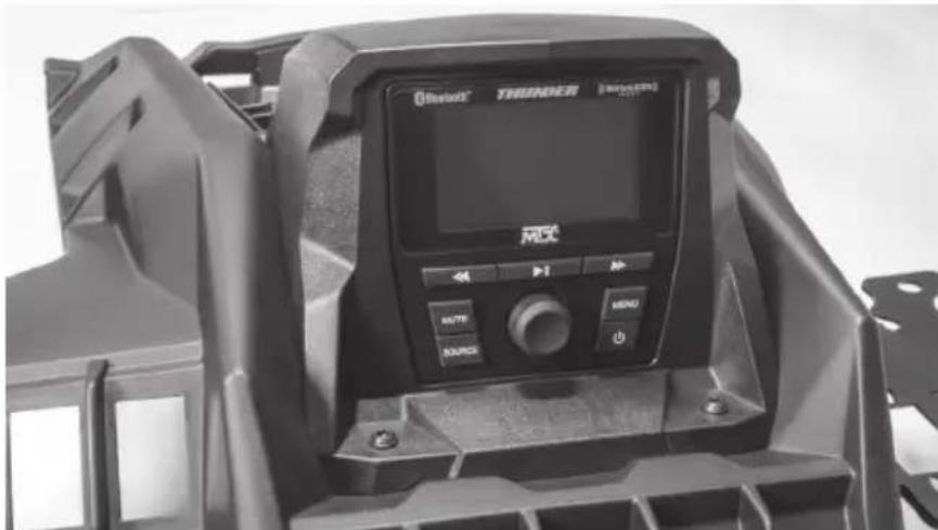
Line drawing of a mechanical device casing with control panel and display screen (no text or symbols)X3-17-DK
CAN-AM® MAVERICK X3 DASH KIT
OWNER'S MANUAL

THANK YOU
Thank you for making the AWESOME decision to purchase our Can-Am® Maverick X3 dash kit designed for use with the MTX Audio AWMC3 Bluetooth all-weather head unit. This easy to install dash kit is the perfect OEM fit solution for your Can-Am® Maverick X3. So, congratulations on your purchase, thanks for your support and most importantly, enjoy the ultimate audio experience with MTX!
WE'RE HERE TO HELP
We're here to help with any installation or technical support. Visit mtx.com to chat, call 1-800-225-5689 to speak with an MTX Technical Support representative, or visit youtube.com/user/MTXAudioUSA to view product videos.
DON'T FORGET TO REGISTER YOUR PRODUCT
Don't forget to register your new MTX Audio product. Visit mtx.com/productregistration or scan the QR code to the right.
Model #
Serial #
Dealer's Name
Date of Purchase

IMPORTANT NOTICE
Whenever working on the vehicle, it is recommended to disconnect the battery prior to starting work. Failure to do so may lead to a risk of electric shock or equipment damage.
When connecting power and ground wires ensure that the red power wire is fused at the point where it is connected to the vehicle's battery. Failure to do so can result in damage to the vehicle if a short circuit develops between the vehicle connection point and the product.

FIT GUIDE
Turbo / Max Turbo....2018 - 2019
Turbo R / Max Turbo R....2017 - 2019
X-DS Turbo 2017
X-RS Turbo R / Max X-RS Turbo R....2017 - 2019
X-DS Turbo R / Max X-DS Turbo R 2018 - 2019
X-MR Turbo 2019 - 2021
X-MR Turbo R....2019
X-RC Turbo 2019 - 2021
X-MC Turbo R....2019
DS Turbo / Max DS Turbo 2020 - 2021
RS Turbo 2020
DS Turbo R / Max DS Turbo R 2020 - 2021
Max DS Turbo RR 2020
RS Turbo R / Max RS Turbo R....2020 - 2021
X-RC Turbo RR 2020 - 2021
X-RS Turbo RR / Max X-RS Turbo RR....2020 - 2021
X-MR Turbo RR / Max X-MR Turbo RR 2020 - 2021
X-MS Turbo RR 2020
X-DS Turbo RR / Max X-DS Turbo RR 2020 - 2021
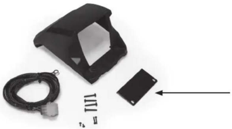
IN THE BOX
- Dash Kit
- Mounting Hardware
(1) Compression Plate
(2) Compression Plate Screws
(4) Shroud Screws
(2) Source Unit Screws
INSTALLATION TOOLS
The following is a list of suggested tools needed for installation:
- 1" Hole Saw
- Torx T8 Screwdriver
- Torx T20 Screwdriver
- Drill and 18 " Drill Bit
INSTALLATION
Step 1 - Remove the cover from top center of the dash.
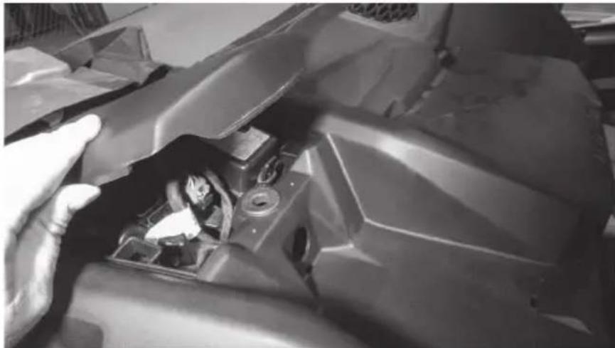
natural_image
Close-up of a mechanical component with visible internal parts and a hand adjusting it (no text or symbols)Step 2 - Locate the four (4) dimples formed into the tray area on the top center dash. Two are located toward the front and two are at the rear under the cover that was just removed. Using a 18 " drill bit, drill through the dimples just enough to expose the existing boss located below. Caution: Drilling deeper can damage the bosses beneath and prevent proper installation of the dash kit.
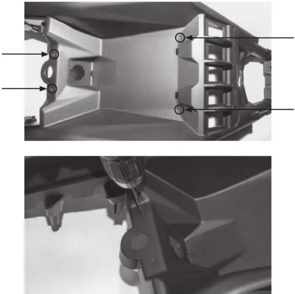
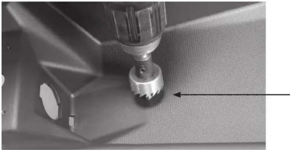
natural_image
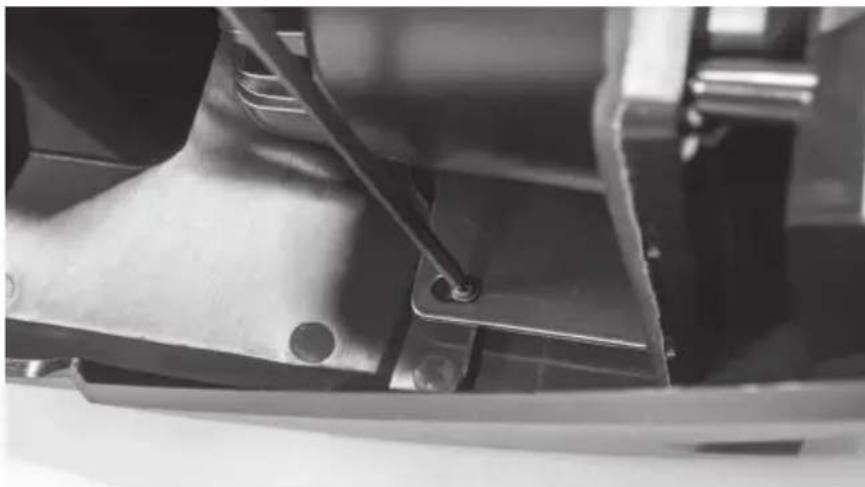
Two grayscale images showing mechanical components with no visible text or symbolsStep 3 - Using a 1" hole saw, drill a hole in the top of the dash to pass the wiring harness through. Our recommended location is indicated in the picture. Note: The 12-volt power port can be removed and used to pass the harness through the dash if you do not desire to drill a separate hole. This will require the removal of the center dash console panel to remove the power port.
natural_image
Close-up of a sewing machine needle stitching fabric, showing mechanical components and a tool (no text or symbols visible)Step 4 - Prepare the AWMC3 radio unit by removing the two (2) threaded studs from the back of the radio.
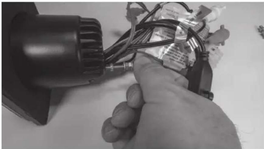
natural_image
Close-up of a hand holding a small electric motor with wires and connectors, no visible text or symbolsStep 5 - Locate the compression plate (shown) in the kit. Install it loosely as shown into the kit by inserting two (2) short screws included.
natural_image
Black plastic enclosure with attached cable and a small black rectangular component, no visible text or symbols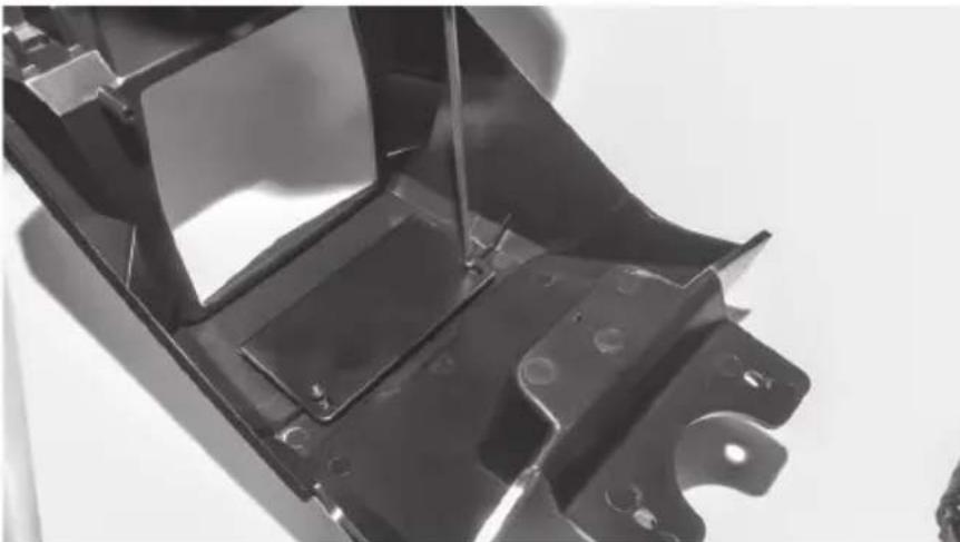
natural_image
Close-up of a metal automotive chassis frame with mounting holes and structural ribs (no text or symbols visible)Step 6 - Sliding the plate toward the rear of the kit, install the radio into the kit opening from the rear making sure the top of the radio is between the kit face and compression plate. Once in position, press the radio forward into the opening until it is flush with the front and aligned with the pre-molded screw holes.
natural_image
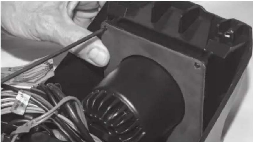
Close-up of a hand using a screwdriver to press or adjust internal components on a device (no visible text or symbols)Step 7 - Using the two (2) longer screws, secure the bottom of the radio to the kit.
natural_image
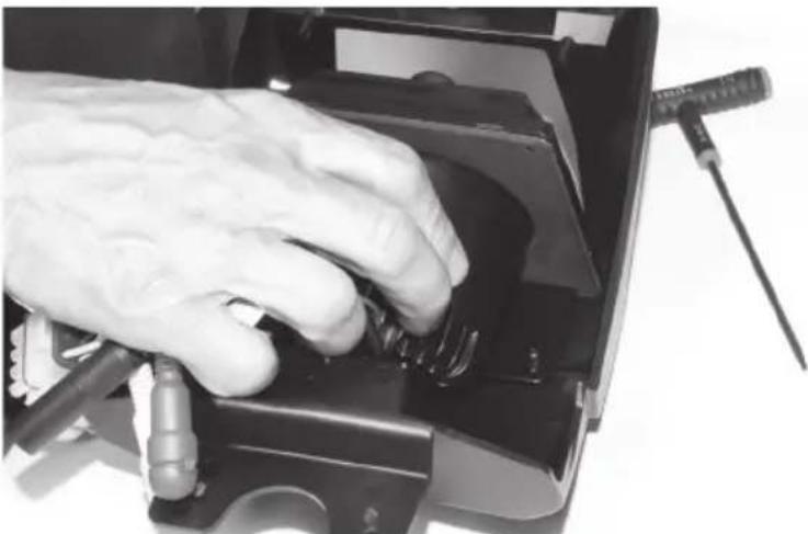
Close-up of hands working on an electrical component with wires and a transformer (no visible text or symbols)Step 8 - While pressing the pressure plate forward against the radio chassis, tighten the two (2) screws left loose in Step 5.
natural_image
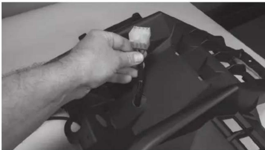
Close-up of a mechanical component with a metal bracket and mounting holes (no visible text or symbols)Step 9 - Prepare the pigtail harness supplied with the AWMC3 radio for installation by connecting additional wire to reach power / ground locations, speaker wire if needed and amplifier turn on wire. Note: If the radio installation is part of a full plug and play kit, use the pigtail supplied with the kit and not the radio. Start the installation by passing the pigtail harness down through the 1" hole previously drilled.
natural_image
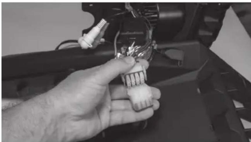
Close-up of a hand adjusting a black plastic component on a table (no visible text or symbols)Step 10 - At this time, any RCA signal wires should be fed up through the hole for connection to the radio unit. Once wires are in place, make the appropriate connections to the radio.
natural_image
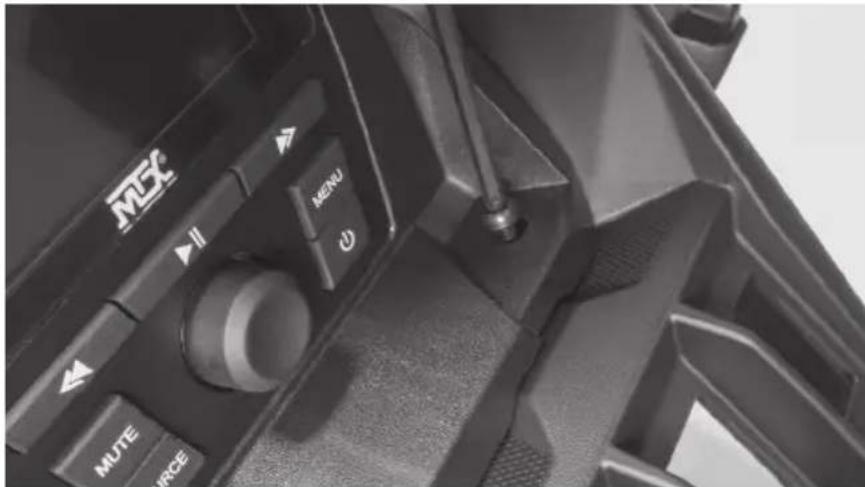
Close-up of a hand holding a small electronic component with wires and connectors (no visible text or symbols)Step 11 - With connections made, collect the wire harness under the kit shroud and place the radio kit on top of the dash aligning it with the four (4) holes drilled earlier. Making sure all wires are tucked under the kit, secure it in place with the four (4) screws provided
Step 12 - With the radio secure, make the appropriate electrical connections to complete the install such as power, ground and remote turn on for amplifiers.
Step 13 - Reassemble and go ride.
WARRANTY PERIOD
At MTX Audio we engineer products that will stand up to the test of time. We also realize that from time to time a problem may occur. That's why our products carry a 2-year limited warranty that begins at the time of sale to the end user.
Of course, we're here to help. If you experience an issue with any of our products within the warranty period, please contact our customer service technical line at 1-800-CALL-MTX to help troubleshoot your issue. If, after speaking with our technical experts it is determined that a problem lies with the product, the technician will provide you with a Return Authorization number and all relevant details you'll need to get the product taken care of.
MITEK WARRANTY
MiTek Mobile products (including, but not limited to: MTX, Coustic, Streetwires, Xtant, BassSlammer, and Thunder Marine) purchased in the USA from an AUTHORIZED MITEK DEALER are guaranteed against defects in material and workmanship for the period of time specified. The warranty period begins the day the product is purchased by the end user, and this warranty is limited to the original retail purchaser of product. Products found to be defective during the warranty period will be repaired or replaced with equivalent product by MiTek at no charge. This warranty is void if it is determined that unauthorized parties have attempted repairs or alterations of any nature, and the warranty does not extend to cosmetics or finish. MiTek disclaims any liability for other incurred or consequential damages resulting from product defects. MiTek's total liability will not exceed the purchase price of the product.
NOTES
NOTES

Let's Get Social
mtx.com

natural_image
Four black square icons representing social media platforms: Instagram, Twitter, Facebook, and YouTube (no text or symbols beyond logos)Like, Follow, & Subscribe
© 2021 MiTek Corporation. All rights reserved. MTX is a trademark of MiTek Corporation. All other trademarks are property of their respective owners. Designed and Engineered in the U.S.A.
Due to continual product development, all specifications are subject to change without notice.
MTX Audio, 4545 East Baseline Rd. Phoenix, AZ 85042 U.S.A. 1-800-225-5689
MTX006220 RevA 1/21 • 21A10809 • AW0015864
Brand : MTX Audio
Model : X3-17-DK
Category : Car radio