
DSPAX620 - Home cinema amp YAMAHA - Free user manual and instructions
Find the device manual for free DSPAX620 YAMAHA in PDF.
| Product type | Home theater amplifier |
| Brand | YAMAHA |
| Model | DSP-AX620 |
| Output power (8 ohms, 20 Hz-20 kHz, 0.06% THD) | 5 x 90 W (main, center, rear) |
| Maximum power (EIAJ, China/general models) | 5 x 115 W (1 kHz, 10% THD) |
| Built-in decoders | Dolby Digital, DTS, Dolby Pro Logic |
| Sound field processor | CINEMA DSP, Hi-Fi DSP, Virtual CINEMA DSP, SILENT CINEMA |
| D/A converter | 96 kHz / 24 bit |
| Audio inputs | 6 (CD, TUNER, MD/CD-R, DVD, D-TV/CBL, VCR1, VCR2/DVR, PHONO, V-AUX) + 6CH input, optical and digital coaxial |
| Outputs | Subwoofer, headphones, Pre-out (Europe/UK models) |
| Video inputs/outputs | S-video, composite, component |
| Remote control | Programmable with manufacturer codes |
| Additional functions | SET MENU (10 parameters), test signal generator, BASS EXTENSION, sleep timer (SLEEP), OSD |
| Dimensions (W x H x D) | 435 x 151 x 390 mm |
| Weight | 10.5 kg |
| Power consumption | 260 W (standby: 0.9 W Europe/UK models) |
| Power supply | 230 V AC, 50 Hz (Europe/UK); 110-240 V AC, 50/60 Hz (general model) |
| Cleaning | Clean, dry cloth, do not use chemicals |
| Manual available | French, English, German, Spanish, Italian, Dutch, Swedish |
Frequently Asked Questions - DSPAX620 YAMAHA
User questions about DSPAX620 YAMAHA
0 question about this device. Answer the ones you know or ask your own.
Ask a new question about this device
Download the instructions for your Home cinema amp in PDF format for free! Find your manual DSPAX620 - YAMAHA and take your electronic device back in hand. On this page are published all the documents necessary for the use of your device. DSPAX620 by YAMAHA.
USER MANUAL DSPAX620 YAMAHA
1 To assure the finest performance, please read this manual carefully. Keep it in a safe place for future reference.
2 Install this unit in a well ventilated, cool, dry, clean place with at least 30 cm on the top, 20 cm on the right and left, and 10 cm at the back of this unit for ventilation space — away from direct sunlight, heat sources, vibration, dust, moisture, and/or cold.
3 Locate this unit away from other electrical appliances, motors, or transformers to avoid humming sounds. To prevent fire or electrical shock, do not place this unit where it may get exposed to rain, water, and/or any type of liquid.
4 Do not expose this unit to sudden temperature changes from cold to hot, and do not locate this unit in a environment with high humidity (i.e. a room with a humidifier) to prevent condensation inside this unit, which may cause an electrical shock, fire, damage to this unit, and/or personal injury.
5 On the top of this unit, do not place:
- Other components, as they may cause damage and/or discoloration on the surface of this unit.
– Burning objects (i.e. candles), as they may cause fire, damage to this unit, and/or personal injury.
- Containers with liquid in them, as they may cause electrical shock to the user and/or damage to this unit.
6 Do not cover this unit with a newspaper, tablecloth, curtain, etc. in order not to obstruct heat radiation. If the temperature inside this unit rises, it may cause fire, damage to this unit, and/or personal injury.
7 Do not plug in this unit to a wall outlet until all connections are complete.
8 Do not operate this unit upside-down. It may overheat, possibly causing damage.
9 Do not use force on switches, knobs and/or cords.
10 When disconnecting the power cord from the wall outlet, grasp the plug; do not pull the cord.
11 Do not clean this unit with chemical solvents; this might damage the finish. Use a clean, dry cloth.
12 Only voltage specified on this unit must be used. Using this unit with a higher voltage than specified is dangerous and may cause fire, damage to this unit, and/or personal injury. YAMAHA will not be held responsible for any damage resulting from use of this unit with a voltage other than specified.
13 To prevent damage by lightning, disconnect the power cord from the wall outlet during an electrical storm.
14 Take care of this unit so that no foreign objects and/or liquid drops inside this unit.
15 Do not attempt to modify or fix this unit. Contact qualified YAMAHA service personnel when any service is needed. The cabinet should never be opened for any reasons.
16 When not planning to use this unit for long periods of time (i.e. vacation), disconnect the AC power plug from the wall outlet.
17 Be sure to read the "TROUBLESHOOTING" section on common operating errors before concluding that this unit is faulty.
18 Before moving this unit, press STANDBY/ON to set this unit in the standby mode, and disconnect the AC power plug from the wall outlet.
19 VOLTAGE SELECTOR (China and General models only)
The VOLTAGE SELECTOR on the rear panel of this unit must be set for your local main voltage BEFORE plugging into the AC main supply. Voltages are 110/120/220/240 V AC, 50/60 Hz.
This unit is not disconnected from the AC power source as long as it is connected to the wall outlet, even if this unit itself is turned off. This state is called the standby mode. In this state, this unit is designed to consume a very small quantity of power.
■For U.K. customers
If the socket outlets in the home are not suitable for the plug supplied with this appliance, it should be cut off and an appropriate 3 pin plug fitted. For details, refer to the instructions described below.
Note
- The plug severed from the mains lead must be destroyed, as a plug with bared flexible cord is hazardous if engaged in a live socket outlet.
■Special Instructions for U.K. Model
IMPORTANT
THE WIRES IN MAINS LEAD ARE COLOURED IN ACCORDANCE WITH THE FOLLOWING CODE:
Blue: NEUTRAL
Brown: LIVE
As the colours of the wires in the mains lead of this apparatus may not correspond with the coloured markings identifying the terminals in your plug, proceed as follows:
The wire which is coloured BLUE must be connected to the terminal which is marked with the letter N or coloured BLACK. The wire which is coloured BROWN must be connected to the terminal which is marked with the letter L or coloured RED.
Making sure that neither core is connected to the earth terminal of the three pin plug.
CONTENTS
INTRODUCTION
FEATURES 2
GETTING STARTED 3
Checking the Package Contents .... 3
Installing Batteries in the Remote Control .... 3
CONTROLS AND FUNCTIONS .... 4
Front Panel 4
Remote Control 6
Description of the Numeric Buttons 7
Using the Remote Control 8
Front Panel Display 9
Rear Panel 10
PREPARATION
SPEAKER SETUP 11
Speakers to Be Used 11
Speaker Placement 11
CONNECTIONS 12
Before Connecting Components ...... 12
Connecting Audio Components .... 12
Connecting Video Components 14
Connecting the Speakers 16
Connecting an External Amplifier (Europe and U.K. models only) 18
Connecting an External Decoder 18
IMPEDANCE SELECTOR Switch 19
Connecting the Power Supply Cords 19
ON-SCREEN DISPLAY (OSD) 20
OSD Modes 20
Selecting the OSD Mode 20
SPEAKER MODE SETTINGS 21
Summary of SPEAKER SET Items 1A through 1E 21
ADJUSTING THE SPEAKER OUTPUT LEVELS 22
Before You Begin 22
Using the Test Tone (TEST DOLBY SUR.) ...... 22
BASIC OPERATION
BASIC PLAYBACK 24
Input Modes and Indications 26
Selecting a Sound Field Program 28
Normal Stereo Reproduction 29
BASIC RECORDING 30
ADVANCED OPERATION
SET MENU 31
Adjusting the Items on the SET MENU 31
1 SPEAKER SET (speaker mode settings) ...... 32
2 L/R BALANCE (balance of the left and right main speakers) 34
3 HP TONE CTRL (headphone tone control) ..... 35
4 I/O ASSIGNMENT 35
5 INPUT MODE (initial input mode) 35
6 DOLBY D. SET (Dolby Digital set) 36
7 DTS SET (DTS LFE level) 36
8 SP DELAY TIME 37
9 DISPLAY SET 37
10MEMORY GUARD 37
Commonly Used Buttons in Any Position of the Selector Dial 41
Controlling the Components Connected to This Unit 41
Button Names and Functions in Each Position ..... 42
Setting the Manufacturer Code 45
Returning to the Factory Setting 46
ADDITIONAL INFORMATION
SOUND FIELD PROGRAM 47
Hi-Fi DSP Programs 47
CINEMA DSP Programs 47
SOUND FIELD PROGRAM PARAMETER EDITING .... 50
What is a sound field? 50
Sound Field Program Parameters 50
Changing Parameter Settings 51
Resetting a Parameter to the Factory-set Value ..... 51
Sound Field Parameter Descriptions 52
APPENDIX
TROUBLESHOOTING 55
SPECIFICATIONS 59
GLOSSARY 60
INDEX 62
FEATURES
Built-in 5-Channel Power Amplifier
◆Minimum RMS Output Power (0.06% THD, 20 Hz – 20 kHz)
Main: 90 W + 90 W (8 Ω)
Center: 90 W (8 Ω)
Rear: 90 W + 90 W (8 Ω)
◆Maximum Power (EIAJ)
[China and General models only]
(10% THD, 1 kHz)
Main: 115 W + 115 W (8 Ω)
Center: 115 W (8 Ω)
Rear: 115 W + 115 W (8 Ω)
Multi-Mode Digital Sound Field Processing
◆DTS Decoder
◆Dolby Pro Logic Decoder
◆Dolby Digital Decoder
◆Hi-Fi DSP
◆CINEMA DSP: Combination of YAMAHA DSP Technology and Dolby Pro Logic, Dolby Digital or DTS
◆Virtual CINEMA DSP
◆SILENT CINEMA
Other Features
◆96-kHz/24-bit D/A Converter
◆“SET MENU” which Provides You with 10 Items for Optimizing This Unit for Your Audio/Video System
◆Test Tone Generator for Easier Speaker Balance Adjustment
◆6-Channel External Decoder Input for Other Future Formats
◆BASS EXTENSION Button for Reinforcing Bass Response
◆On Screen Display Function Helpful in Controlling This Unit
◆S Video Signal Input/Output Capability
◆Component Video Input/Output Capability
◆Optical and Coaxial Digital Audio Signal Jacks
◆Sleep Timer
◆Remote Control with Preset Manufacturer Codes
• indicates a tip for your operation.
- Some operations can be performed by using either the buttons on the main unit or on the remote control. In cases when the button names differ between the main unit and the remote control, the button name on the remote control is given in parentheses in this manual.

Manufactured under license from Dolby Laboratories.
"Dolby", "AC-3", "Pro Logic" and the double-D symbol are trademarks of Dolby Laboratories. Confidential Unpublished Works. ©1992-1997 Dolby Laboratories, Inc. All rights reserved.

Manufactured under license from Digital Theater Systems, Inc. US Pat. No. 5,451,942 and other world-wide patents issued and pending. "DTS" and "DTS Digital Surround" are trademarks of Digital Theater Systems, Inc. Copyright 1996 Digital Theater Systems, Inc. All Rights Reserved.
GETTING STARTED
Checking the Package Contents
Check your package to make sure it has the following items.
Remote control
Batteries (4)
(AAA, R03, UM-4)

natural_image
Line drawing of four cylindrical batteries with visible battery terminals (no text or symbols)Quick Reference Card
flowchart
graph TD
    A["Main Device 1"] --> B["Device 1"]
    A --> C["Device 2"]
    A --> D["Device 3"]
    B --> E["External Components"]
    C --> F["External Components"]
    D --> G["External Components"]
Connection guide
flowchart
graph TD
    A["Central Device"] --> B["Component 1"]
    A --> C["Component 2"]
    A --> D["Component 3"]
    A --> E["Component 4"]
    A --> F["Component 5"]
    A --> G["Component 6"]
    A --> H["Component 7"]
    A --> I["Component 8"]
    A --> J["Component 9"]
    A --> K["Component 10"]
    A --> L["Component 11"]
    A --> M["Component 12"]
    A --> N["Component 13"]
    A --> O["Component 14"]
    A --> P["Component 15"]
    A --> Q["Component 16"]
    A --> R["Component 17"]
    A --> S["Component 18"]
    A --> T["Component 19"]
    A --> U["Component 20"]
    A --> V["Component 21"]
    A --> W["Component 22"]
    A --> X["Component 23"]
    A --> Y["Component 24"]
    A --> Z["Component 25"]
    A --> AA["Component 26"]
    A --> AB["Component 27"]
    A --> AC["Component 28"]
    A --> AD["Component 29"]
    A --> AE["Component 30"]
    A --> AF["Component 31"]
    A --> AG["Component 32"]
    A --> AH["Component 33"]
    A --> AI["Component 34"]
    A --> AJ["Component 35"]
    A --> AK["Component 36"]
    A --> AL["Component 37"]
    A --> AM["Component 38"]
    A --> AN["Component 39"]
    A --> AO["Component 40"]
    A --> AP["Component 41"]
    A --> AQ["Component 42"]
    A --> AR["Component 43"]
    A --> AS["Component 44"]
    A --> AT["Component 45"]
    A --> AU["Component 46"]
    A --> AV["Component 47"]
    A --> AW["Component 48"]
    A --> AX["Component 49"]
    A --> AY["Component 50"]
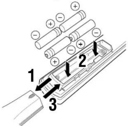
Installing Batteries in the Remote Control
Insert the batteries in the correct direction by aligning the + and - marks on the batteries with the polarity markings (+ and -) inside the battery compartment.
■Notes on batteries
- Change the batteries periodically.
- Do not use old batteries together with new ones.
- Do not use different types of batteries (such as alkaline and manganese batteries) together. Read the packaging carefully as these different types of batteries may have the same shape and color.
■Changing batteries
As the batteries lose power, the operating range of the remote control decreases and the indicator does not flash or its light becomes dim. When you notice any of these conditions, change all of the batteries.
If the remote control is without batteries for more than 2 minutes, or if exhausted batteries remain in the remote control, the contents of the memory may be cleared. When the memory is cleared, insert new batteries, set up the manufacturer code that may have been cleared.
Note
- If the batteries have leaked, dispose of them immediately. Avoid touching the leaked material or letting it come into contact with clothing, etc. Clean the battery compartment thoroughly before installing new batteries.
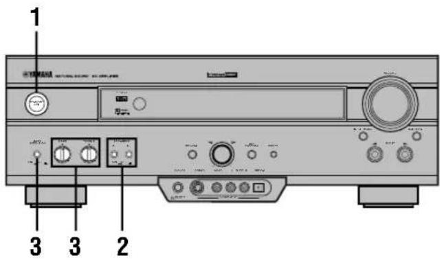
CONTROLS AND FUNCTIONS
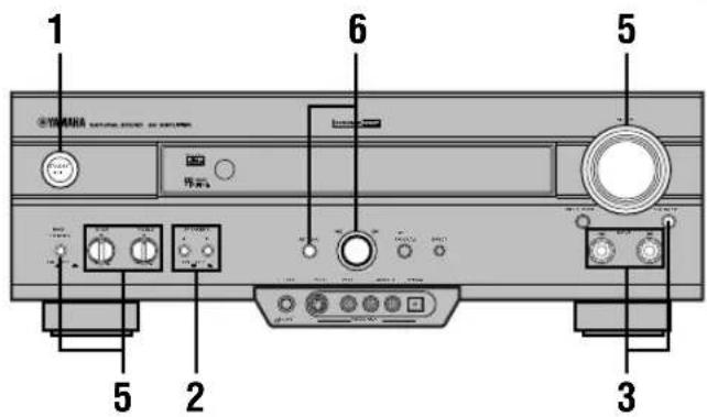
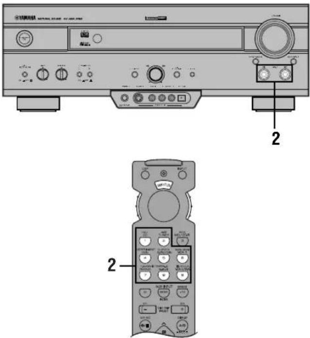
Front Panel
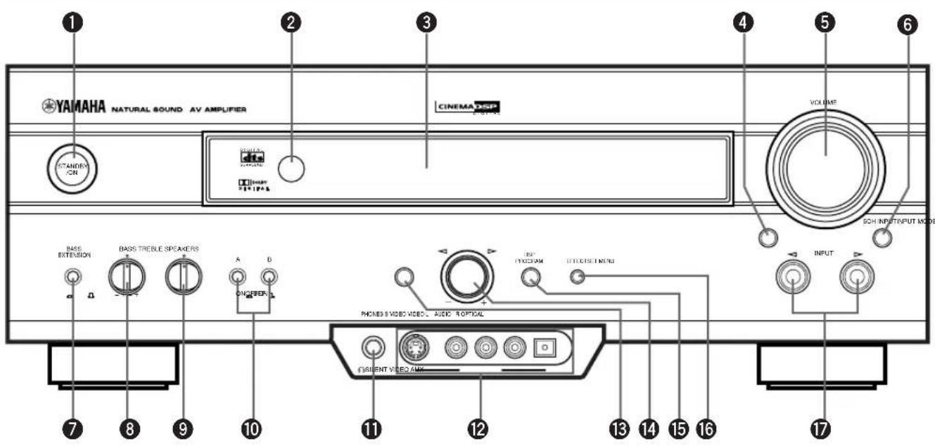
①STANDBY/ON
Turns on or sets this unit in the standby mode. When you turn on this unit, you will hear a click and there will be a 4 to 5-second delay before this unit can reproduce sound.
Standby mode
In this mode, this unit consumes a small amount of power to receive infrared-signals from the remote control.
②Remote control sensor
Receives signals from the remote control.
③Front panel display
Shows information about the operational status of this unit.
④ INPUT MODE
Selects the mode of input for sources that send two or more types of signals to this unit (see page 26 for details). You cannot control the input mode when you select 6CH INPUT as the input source.
⑤VOLUME
Controls the output level of all audio channels. This does not affect the REC OUT level.
66CH INPUT
Selects the source connected to the 6CH INPUT jacks. The source selected by pressing 6CH INPUT takes priority over the source selected with INPUT ◀/▷ (or the input selector buttons on the remote control).
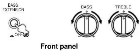
⑦BASS EXTENSION ON/OFF
When pushed in (ON), this feature boosts the bass frequency of the left and right main speakers by +6 dB (60 Hz) while maintaining overall tonal balance. This boost is useful if you do not use a subwoofer. However, this boost may not be noticeable if “1B MAIN SP” on the SET MENU is set to SMALL and “1D LFE/ BASS OUT” is set to SWFR.
8BASS
Adjusts the low-frequency response for the left and right main speakers.
Turn the control to the right to increase or to the left to decrease the low-frequency response.
⑨TREBLE
Adjusts the high-frequency response for the left and right main speakers.
Turn the control to the right to increase or to the left to decrease the high-frequency response.
Note
- If you increase or decrease the high-frequency or the low-frequency sound to an extreme level, the tonal quality from the center and rear speakers may not match that of the left and right main speakers.
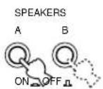
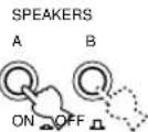
⑩ SPEAKERS A/B
When pushed in (ON), these buttons turn on the set of main speakers connected to the A and/or B terminals on the rear panel.
11PHONES jack
Outputs audio signals for private listening with headphones. When you connect headphones, no signals are output to the speakers.

(Europe and U.K. models only)
- When you connect headphones, no signals are also output to the OUTPUT jacks.
12VIDEO AUX jacks
Inputs audio and video signals from a portable external source such as a game console. To reproduce source signals from these jacks, select V-AUX as the input source.
13SET MENU
Enters the SET MENU.
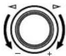
⑭Multi jog knob
Selects and adjust the SET MENU item after pressing SET MENU.
Selects the DSP program after pressing DSP PROGRAM.
⑮DSP PROGRAM
Switches the function of the multi jog knob for selecting DSP program.
16 EFFECT
Switches the effect speakers (center and rear) on and off. If you turn off the output of these speakers by using EFFECT, all Dolby Digital and DTS audio signals except for the LFE channel are directed to the main left and right channels.
When Dolby Digital or DTS signals are mixed, the left and right main channel signal levels may not match.
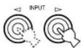
⑰ INPUT ◀/▶
Selects the input source (CD, TUNER, MD/CD-R, DVD, D-TV/CBL, VCR 1, PHONO, V-AUX, VCR 2/DVR) you want to listen to or watch.
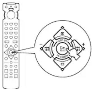
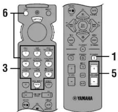
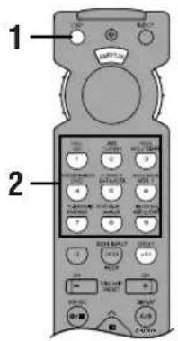
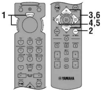
Remote Control
This section describes the basic operation of this unit with the remote control. First, set the selector dial to the AMP/TUN position. See “REMOTE CONTROL FEATURES” for full details.
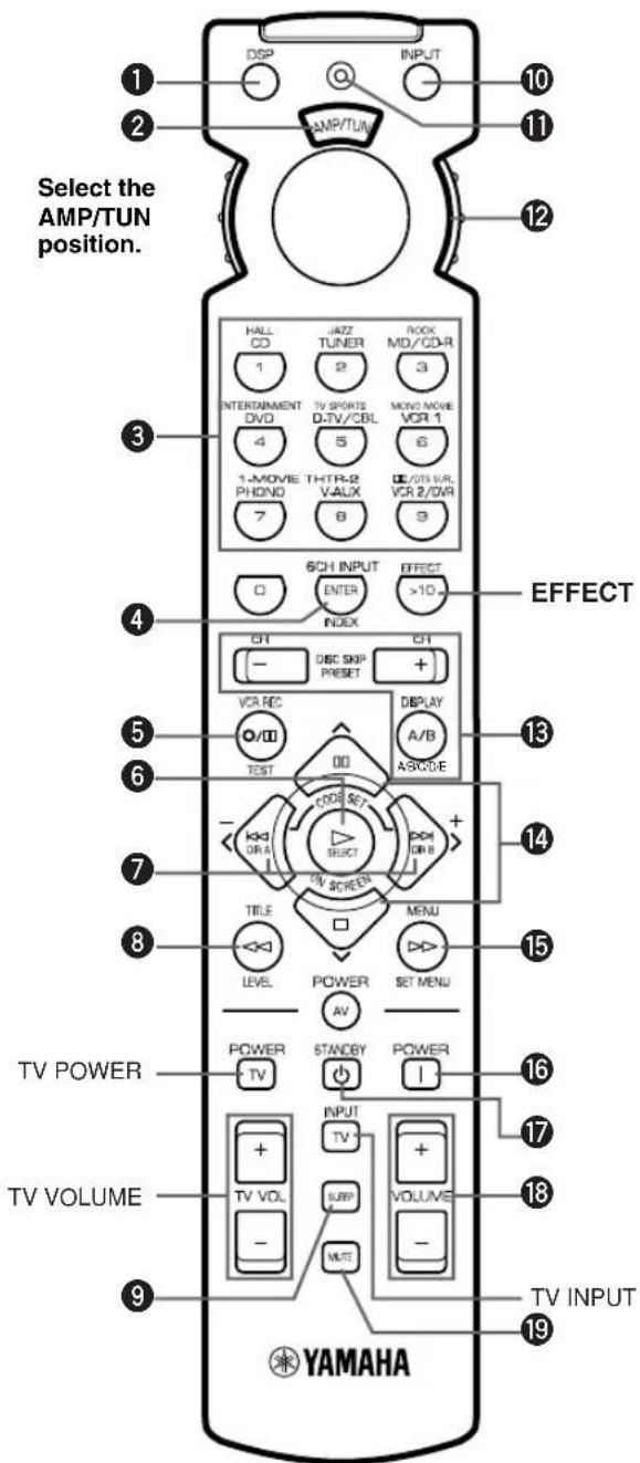
①DSP
Switches the function of the numeric buttons to the DSP program selector.
②Indicator window
Shows the name of components which can be controlled.
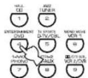
③Numeric buttons (Input selector buttons)
These buttons select the input source.
See "Description of the Numeric Buttons" for the numeric buttons.
46CH INPUT
Selects the source connected to the 6CH INPUT jacks.
5TEST
Outputs the test tone.
⑥ ON SCREEN
Selects the on-screen display (OSD) mode for your video monitor.
⑦ (-I+)
Adjust DSP program parameters and SET MENU items. - / + is displayed on the on-screen display.
8 LEVEL
Selects the effect speaker channel (center, rear and subwoofer) so you can adjust their output level independently.
⑨SLEEP
Sets the sleep timer.
⑩INPUT
Switches the function of the numeric buttons to the input selector.
⑪Indicator
Flashes while the remote control is sending signals.
⑫Selector dial
Turn this dial to select the position for the component to be controlled. (The proper code must be set up for your component. See “Setting the Manufacture Codes”.) When a position is selected, the remote control is set to that component operation mode.
⑬A/B/C/D/E, PRESET -/+
These buttons are used to select a preset station when using YAMAHA tuner.
A/B/C/D/E: To select one of 5 preset station groups (A to E)
PRESET -/+: To select a preset station number (1 to 8)
14
Select DSP program parameters and SET MENU items.
15SET MENU
Enters the SET MENU.
16 POWER
Turns on the power of this unit.
⑰STANDBY
Sets this unit in the standby mode.
18VOLUME +/-
Increases or decreases the volume level.
19MUTE
Mutes the sound. Press again to restore the audio output to the previous volume level.
EFFECT
Switches the effect speakers (center and rear) on and off in the following cases:
- When the selector dial is set to the DSP/TUN position.
- While the indicator is lit for about 3 seconds after pressing DSP.
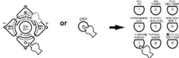
Description of the Numeric Buttons
The numeric buttons function in various ways depending on the position of the selector dial or the combination of other instructions.
■When selecting an input source
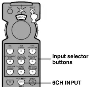
1 Press INPUT regardless of the position of the selector dial.
The indicator lights up for about 3 seconds.
2 You can select an input source with the numeric buttons and 6CH INPUT while the indicator is lit.
■When selecting a DSP program and turning on or off the effect speakers (center and rear)
A
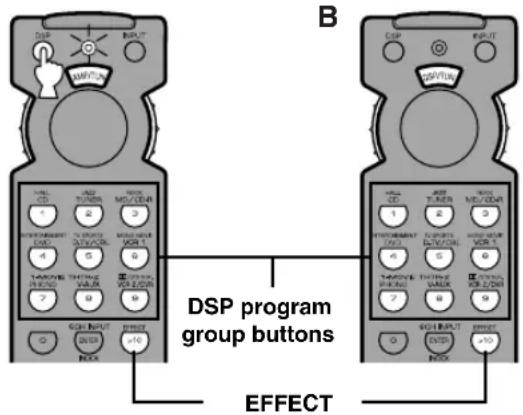
A
1 Press DSP regardless of the position of the selector dial.
The indicator lights up for about 3 seconds.
2 You can select a DSP program with the numeric buttons and turn on or off the effect speakers (center and rear) by pressing EFFECT while the indicator is lit.
B
1 Set the selector dial to the DSP/TUN position.
2 You can select a DSP program directly with the numeric buttons and turn on or off the effect speakers (center and rear) by pressing EFFECT.
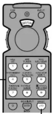
Using the Remote Control
The remote control transmits a directional infrared beam. Be sure to aim the remote control directly at the remote control sensor on the main unit during operation.
■Handling the remote control
- Do not spill water or other liquids on the remote control.
- Do not drop the remote control.
- Do not leave or store the remote control in the following types of conditions:
– high humidity or temperature such as near a heater, stove or bath; - dusty places; or
– in places subject to extremely low temperatures. - high humidity or temperature such as near a heater, stove or bath;
- dusty places; or
- in places subject to extremely low temperatures.
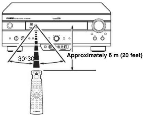
Front Panel Display
flowchart
graph LR
    A[" dts "] --> B[" VIRTUAL "]
    B --> C[" Digital "]
    B --> D[" PRO LOGIC "]
    B --> E[" DSP "]
    B --> F[" PCM "]
    C --> G[" V-AUX "]
    C --> H[" VCR2/DVR "]
    C --> I[" VCR 1 "]
    C --> J[" D-TV/CBL "]
    C --> K[" DVD "]
    C --> L[" MD/CD-R "]
    C --> M[" TUNER "]
    C --> N[" CD "]
    C --> O[" PHONO ' "]
    P[" SLEEP "] --> Q[" dB ms "]
    Q --> R[" VOLUME "]
    R --> S[" 10"]
    R --> T[" 11"]
①dts indicator
Lights up when the built-in DTS decoder is on.
②VIRTUAL indicator
Lights up when using Virtual CINEMA DSP.
3 DIGITAL and PRO LOGIC indicators
Light up according to the type of Dolby signals this unit is reproducing. “☐ DIGITAL” lights up when the built-in Dolby Digital decoder is on. “☐ PRO LOGIC” lights up when the built-in Dolby Pro Logic decoder is on.
④ Input source indicator
Shows the current input source with a cursor.
⑤ DSP indicator
Lights up when you select a DSP program.
6 PCM indicator
Lights up when this unit is reproducing PCM (pulse code modulation) digital audio signals.
⑦Headphones indicator
Lights up when headphones are connected.
⑧DSP program indicators
The name of the selected DSP program lights up when the ENTERTAINMENT, MOVIE THEATER 1, MOVIE THEATER 2 or ☐☐/DTS SURROUND DSP program is selected.
⑨Multi-information display
Shows the current DSP program name and other information when adjusting or changing settings.
⑩VOLUME level indicator
Indicates the volume level.
⑪SLEEP indicator
Lights up while the sleep timer is on.
Rear Panel
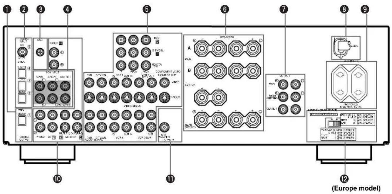
① DIGITAL OUTPUT jacks
② DIGITAL INPUT jacks
③GND terminal
See page 12 for connection information.
④6CH INPUT jacks
See page 18 for connection information.
⑤Video component jacks
See pages 14 and 15 for connection information.
⑥Speaker terminals
See pages 16 and 17 for connection information.
⑦ OUTPUT jacks (Europe and U.K. models only)
See page 18 for connection information.
⑧ AC power cord
Connect to a power outlet.
⑨ AC OUTLET(S)
Use these outlets to supply power to your other audio/video components (see page 19).
⑩Audio component jacks
See pages 12 and 13 for connection information.
⑪SUBWOOFER jack
See page 17 for connection information.
⑫IMPEDANCE SELECTOR switch
Use this switch to match the amplifier output to your speaker impedance. Set this unit in the standby mode before you change the setting of this switch (see page 19).
China and General models only
VOLTAGE SELECTOR
See page 19.
SPEAKER SETUP
Speakers to Be Used
This unit has been designed to provide the best sound-field quality with a 5-speaker system, using left and right main speakers, left and right rear speakers, and a center speaker. If you use different brands of speakers (with different tonal qualities) in your system, the tone of a moving human voice and other types of sound may not shift smoothly. We recommend that you use speakers from the same manufacturer to ensure even tonal quality.
The main speakers are used for the main source sound plus the effect sounds. They will probably be the speakers from your present stereo system. The rear speakers are used for the effect and surround sounds, and the center speaker is for the center sounds (dialog, vocals, etc.). If for some reason it is not practical to use a center speaker, you can do without it. Best results, however, are obtained with the full system.
The main speakers should be high-performance models and have enough power-handling capacity to accept the maximum output of your audio system. The other speakers do not have to be equal to the main speakers. For precise sound localization, however, it is ideal to use high-performance models that can reproduce sounds over the full range for the center speaker and the rear speakers.
■Use of a subwoofer expands your sound field
It is also possible to further expand your system with the addition of a subwoofer. The use of a subwoofer is effective not only for reinforcing bass frequencies from any or all channels, but also for reproducing the LFE (low-frequency effect) channel with high fidelity when the Dolby Digital signal or the DTS signal is played back. The YAMAHA Active Servo Processing Subwoofer System is ideal for natural and lively bass reproduction.
Speaker Placement
Refer to the following diagram when you place the speakers.
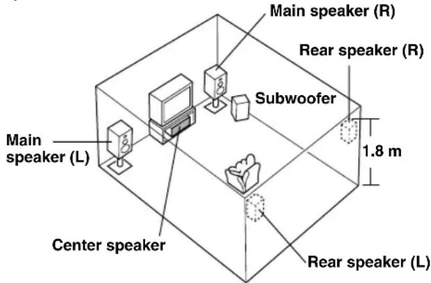
■Main speakers
Place the left and right main speakers an equal distance from the ideal listening position. The distance of each speaker from each side of the video monitor should be the same.
■Rear speakers
Place these speakers behind your listening position, facing slightly inwards, nearly 1.8 m (approx. 6 feet) above the floor.
■Center speaker
Align the front face of the center speaker with the front face of your video monitor. Place the speaker as close to the monitor as possible, such as directly over or under the monitor and centrally between the main speakers.
Note
- If the center speaker is not used, the center channel sound will be heard from the left and right main speakers. In this case, "1A CENTER SP" on the SET MENU is set to NONE.
Subwoofer
The position of the subwoofer is not so critical, because low bass sounds are not highly directional. But it is better to place the subwoofer near the main speakers. Turn it slightly toward the center of the room to reduce the wall reflections.
CAUTION
Please use magnetically shielded speakers. Sometimes a video monitor may be adversely affected even when magnetically shielded speakers are used. Separate the speakers from the monitor if this happens.
CONNECTIONS
Before Connecting Components
CAUTION
Never connect this unit and other components to mains power until all connections between components have been completed.
- Be sure all connections are made correctly, that is to say L (left) to L, R (right) to R, “+” to “+” and “−” to “−”. Some components require different connection methods and have different jack names. Refer to the operation instructions for each component to be connected to this unit.
- When you connect other YAMAHA audio components (such as a tape deck, MD recorder and CD player or changer), connect them to the jack with the same number labels as 1, 2, 3 etc.
• After you have completed all connections, check them again to make sure they are correct.
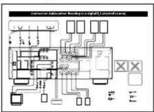
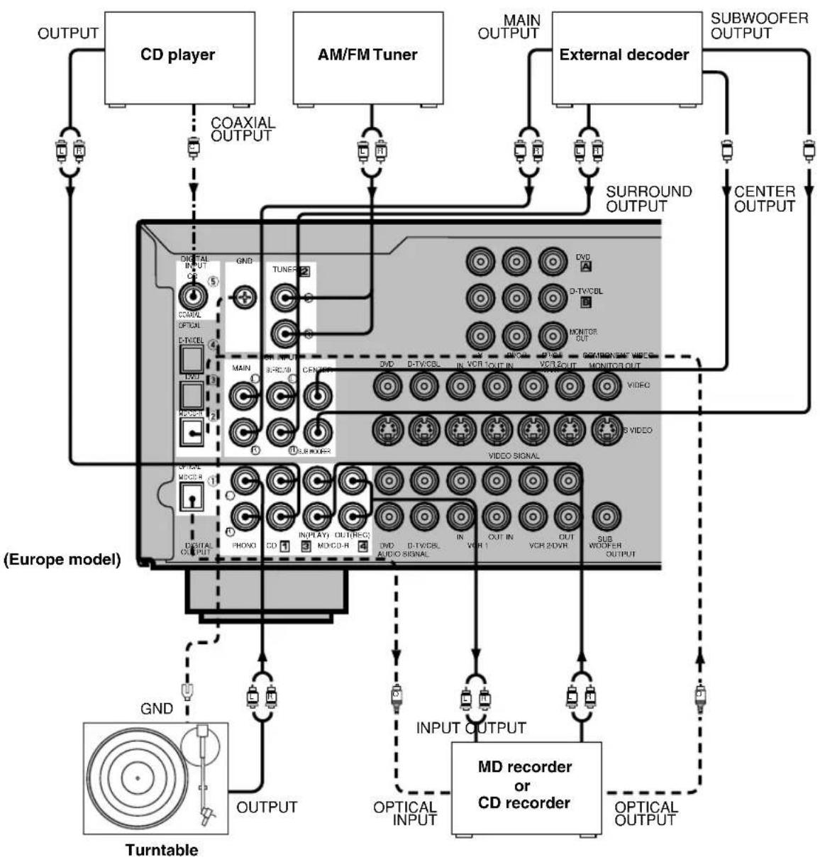
Connecting Audio Components
■Connecting to digital jacks
This unit has digital jacks for direct transmission of digital signals through either coaxial or fiber optic cables. You can use the digital jacks to input PCM, Dolby Digital and DTS bitstreams. When you connect components to both the COAXIAL and OPTICAL jacks, priority is given to the input signals from the COAXIAL jack. All digital input jacks are acceptable for 96-kHz sampling digital signals.

- You can designate the input for each digital jack according to your component by using "4 I/O ASSIGNMENT" on the SET MENU.
About the dust protection cap
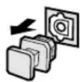
Pull out the cap from the optical jack before you connect the fiber optic cable. Do not discard the cap. When you are not using the optical jack, be sure to put the cap back in place. This cap protects the jack from dust.
Note
- The OPTICAL jacks on this unit conform to the EIA standard. If you use a fiber optic cable that does not conform to this standard, this unit may not function properly.
■Connecting a turntable
PHONO jacks are for connecting a turntable with an MM or high-output MC cartridge. If you have a turntable with a low-output MC cartridge, use an inline boosting transformer or MC-head amplifier when connecting to these jacks.

- The GND terminal does not electrically ground the turntable. It simply reduces noise in the signal. In some cases, you may hear less noise if you do not connect to the GND terminal.
■Connecting a tuner
You can listen to an FM or AM broadcasting by connecting AM/FM tuner.
To get clearer reception, connect the antennas correctly. Refer to your tuner's operation instructions for details.
■Connecting a CD player

- The COAXIAL jack is available for a CD player which has a coaxial digital output jack.
- When you connect a CD player to both the analog and digital jacks, priority is given to the input signals from the digital jack.
■Connecting an MD recorder, CD recorder or tape deck

- When you connect your recording component to both the analog and digital input and output jacks, the priority is given to the digital signal.
Notes
- When you connect a recording component to this unit, keep its power on while using this unit. If the power is off, this unit may distort the sound from other components.
- Since digital output and analog output (REC OUT) are independent of each other, the analog signal is output only to the analog jack, while the digital signal is output only to the digital jack.
flowchart
graph TD
    A["OUTPUT"] --> B["CD player"]
    C["AM/FM Tuner"] --> D["External decoder"]
    E["OUTPUT"] --> F["CD player"]
    G["OUTPUT"] --> H["CD player"]
    I["OUTPUT"] --> J["CD player"]
    K["OUTPUT"] --> L["CD player"]
    M["OUTPUT"] --> N["CD player"]
    O["OUTPUT"] --> P["CD player"]
    Q["OUTPUT"] --> R["CD player"]
    S["OUTPUT"] --> T["CD player"]
    U["OUTPUT"] --> V["CD player"]
    W["OUTPUT"] --> X["CD player"]
    Y["OUTPUT"] --> Z["CD player"]
    AA["OUTPUT"] --> AB["CD player"]
    AC["OUTPUT"] --> AD["CD player"]
    AE["OUTPUT"] --> AF["CD player"]
    AG["OUTPUT"] --> AH["CD player"]
    AI["OUTPUT"] --> AJ["CD player"]
    AK["OUTPUT"] --> AL["CD player"]
    AM["OUTPUT"] --> AN["CD player"]
    AO["OUTPUT"] --> AP["CD player"]
    AQ["OUTPUT"] --> AR["CD player"]
    AS["OUTPUT"] --> AT["CD player"]
    AU["OUTPUT"] --> AV["CD player"]
    AW["OUTPUT"] --> AX["CD player"]
    AY["COAXIAL OUTPUT"] --> AZ["GND"]
    BA["SURROUND OUTPUT"] --> BB["DVD"]
    BC["CENTER OUTPUT"] --> BD["DVD"]
    BE["SURROUND OUTPUT"] --> BF["DVD"]
    BG["CENTER OUTPUT"] --> BH["DVD"]
    BI["VOC1 OUT"] --> BJ["DVD"]
    BK["VOC2 OUT"] --> BL["DVD"]
    BM["VOC3 OUT"] --> BN["DVD"]
    BO["VOC4 OUT"] --> BP["DVD"]
    BQ["VOC5 OUT"] --> BR["DVD"]
    BS["VOC6 OUT"] --> BT["DVD"]
    BU["VOC7 OUT"] --> BV["DVD"]
    BW["VOC8 OUT"] --> BX["DVD"]
    BY["VOC9 OUT"] --> BZ["DVD"]
    CA["VOC10 OUT"] --> CB["DVD"]
    CC["VOC11 OUT"] --> CD["DVD"]
    CE["VOC12 OUT"] --> CF["DVD"]
    CG["VOC13 OUT"] --> DH["DVD"]
    DI["VOC14 OUT"] --> DJ["DVD"]
    DK["VOC15 OUT"] --> DL["DVD"]
    DV["VOC16 OUT"] --> DW["DVD"]
    DX["VOC17 OUT"] --> DXD["DVD"]
    DXV["VOC18 OUT"] --> DXR["DVD"]
    DXVX["VOC19 OUT"] --> DXR
    DXVX --> DXR
    DXVX --> DXR
    DXVX --> DXR
    DXVX --> DXR
    DXVX --> DXR
    DXVX --> DXR
    DXVX --> DXR
    DXVX --> DXR
    DXVX --> DXR
    DXVX --> DXR
    DXVX --> DXR
    DXVX --> DXR
    DXVX --> DXR
indicates signal direction
indicates left analog cables
indicates right analog cables
indicates optical cables
indicates coaxial cables
Connecting Video Components
■About the video jacks
There are three types of video jacks. Video signals input through the VIDEO jacks are the conventional composite video signals. Video signals input through the S VIDEO jacks are separated into luminance (Y) and color (C) video signals. The S-video signals achieve high-quality color reproduction. Video signals input through the COMPONENT VIDEO jacks are separated into luminance (Y) and color difference (P_B / C_B,P_R / C_R) video signals. The jacks are also separated into three for each signal. The description of the component video jacks may be different depending on the component (e.g. Y, C_B,C_R / Y,P_B,P_R / Y,B - Y,R - Y etc.). Component video signals provide the best quality in picture reproduction.
If your video component has an S-video output or component video output, you can connect it to this unit. Connect the S-video signal output jack on your video component to the S VIDEO jack or connect the component signal output jacks on your video component to the COMPONENT VIDEO jacks.


• Each type of video jack works independently. Signals input through the composite video, S-video and component jacks are output through the corresponding composite video, S-video, and component jacks, respectively.
- If you make S-video connections to this unit, it is not necessary to make composite video connections. If both types of connections are made, this unit gives priority to the S-video signal.
- You can designate the input for the COMPONENT VIDEO A and B jacks according to your component by using “4 I/O ASSIGNMENT” on the SET MENU.
Notes
- Use a commercially available S-video cable when connecting to the S VIDEO jack, and commercially available video cables when connecting to the COMPONENT VIDEO jacks.
- When you are using the COMPONENT VIDEO jacks, check the details in the owner's manual that came with the component being connected.
■Video monitor with a 21-pin connector (Europe and U.K. models only)
Make a connection as shown on page 15 with a commercially available SCART-plug connector cable.
■VIDEO AUX jacks (on the front panel)
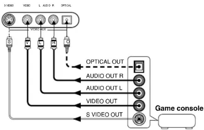
flowchart
graph TD
    A["S VIDEO"] --> B["VIDEO AUX"]
    C["V"] --> B
    D["L"] --> B
    E["H"] --> B
    F["C"] --> B
    B --> G["OPTICAL OUT"]
    B --> H["AUDIO OUT R"]
    B --> I["AUDIO OUT L"]
    B --> J["VIDEO OUT"]
    B --> K["S VIDEO OUT"]
    G --> L["Game console"]
    H --> L
    I --> L
    J --> L
    K --> L
These jacks are used to connect any video input source such as a game console to this unit.
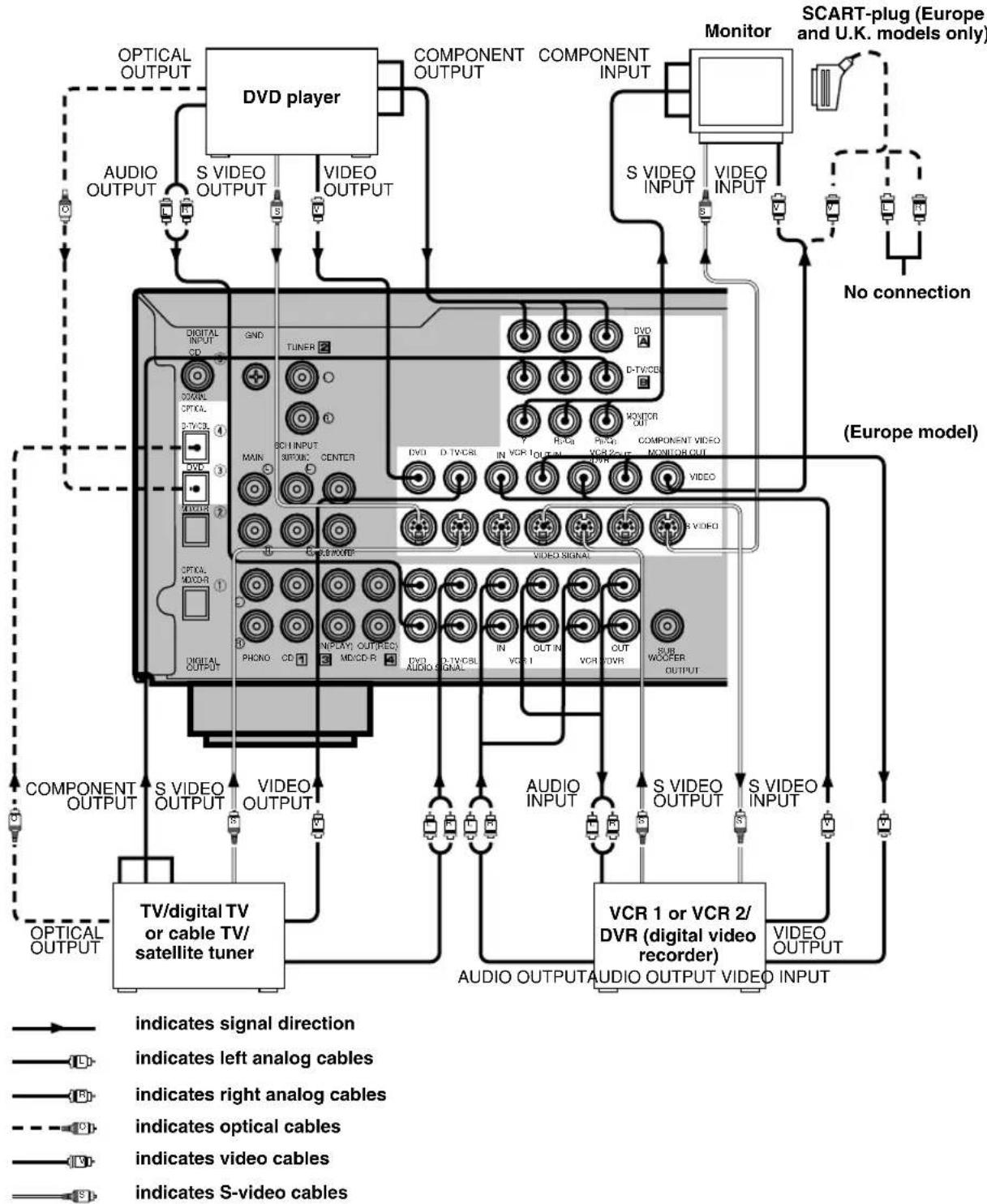
flowchart
TV/DVD system architecture diagram showing connections between video output, audio outputs, and monitor components with labels for optical, video, and digital media.When using an LD player
Connect the LD player output to the DVD jack.
If the LD player has an OPTICAL digital output jack, connect it to this unit's OPTICAL DVD jack. If it has analog jacks, connect it to the analog DVD jacks. If it has an "RF OUTPUT jack" to output a Dolby Digital RF signal (AC-3), use a commercially available RF demodulator and connect it to the OPTICAL DVD jack.
If connecting a DVD player and an LD player, connect the LD player to the digital input jack (ex. D-TV/CBL) or to the analog input jack (D-TV/CBL, VCR 1 or VCR 2/DVR). For details on connections and operations, refer to the operation instructions for the LD player.
Note that this unit's remote control can be used to operate the LD player by setting the corresponding manufacturer code for the DVD/LD position.
Connecting the Speakers
Be sure to connect the left channel (L), right channel (R), “+” (red) and “−” (black) properly. If the connections are faulty, no sound will be heard from the speakers, and if the polarity of the speaker connections is incorrect, the sound will be unnatural and lack bass.
CAUTION
- Use speakers with the specified impedance shown on the rear panel of this unit.
- Do not let the bare speaker wires touch each other and do not let them touch any metal part of this unit. This could damage the unit and/or speakers.
If necessary, use the SET MENU to change the speaker mode settings according to the number and size of the speakers in your configuration after you finish connecting your speakers.
■Speaker cables
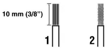
A speaker cord is actually a pair of insulated cables running side by side. One of the cables is colored or shaped differently, perhaps with a stripe, groove or ridge.
1 Remove approx. 10 mm (3/8") of insulation from each of the speaker cables.
2 Twist the exposed wires of the cable together to prevent short circuits.
■Connecting to the SPEAKERS terminals
Red: positive (+)
Black: negative (−)
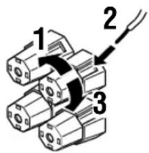
1 Unscrew the knob.
2 Insert one bare wire into the hole in the side of each terminal.
3 Tighten the knob to secure the wire.
Banana plug
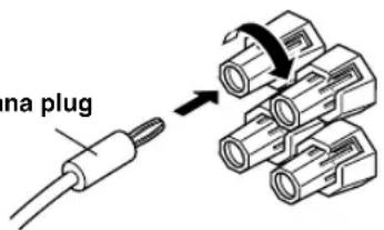

(China and General models only)
- Banana plug connections are also possible. First, tighten the knob and then insert the banana plug connector into the end of the corresponding terminal.
■MAIN SPEAKERS terminals
One or two speaker systems can be connected to these terminals. If you use only one speaker system, connect it to either of the MAIN A or B terminals.
■REAR SPEAKERS terminals
A rear speaker system can be connected to these terminals.
■CENTER SPEAKER terminals
A center speaker can be connected to these terminals.
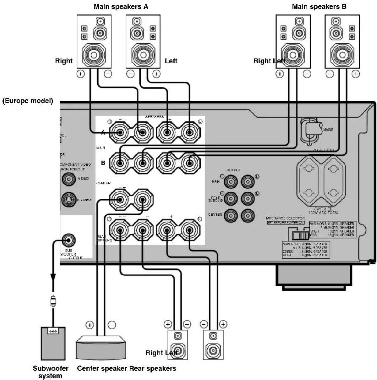
SUBWOOFER jack
When using a subwoofer with built-in amplifier, including the YAMAHA Active Servo Processing Subwoofer System, connect the input jack of the subwoofer system to this jack. Low bass signals distributed from the main, center and/or rear channels are directed to this jack. (The cut-off frequency of this jack is 90 Hz.) The LFE (low-frequency effect) signals generated when Dolby Digital or DTS is decoded are also directed if they are assigned to this jack.
Notes
- Adjust the subwoofer volume according to the operating instructions for the subwoofer. (Fine adjustment is possible using this unit's output level control of the effect speakers.)
- Depending on the settings of "1 SPEAKER SET", "6 DOLBY D. SET" and "7 DTS SET" on the SET MENU, some signals may not be output from the SUBWOOFER jack.
Connecting an External Amplifier (Europe and U.K. models only)
If you want to increase the power output to the speakers, or want to use another amplifier, connect an external amplifier to the OUTPUT jacks as follows.
Note
- When RCA pin plugs are connected to the OUTPUT jacks for output to an external amplifier, do not use the corresponding SPEAKERS terminals.
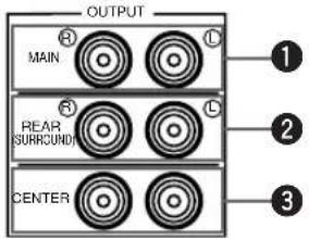
①MAIN jacks
Main channel line output jacks.
Note
- The signals output through these jacks are affected by the BASS, TREBLE and BASS EXTENSION settings.
② REAR (SURROUND) jacks
Rear channel line output jacks.
③CENTER jacks
Center channel line output jacks.
Connecting an External Decoder
This unit is equipped with 6 additional input jacks (left and right MAIN, CENTER, left and right SURROUND and SUBWOOFER) for discrete multi-channel input from an external decoder, sound processor or pre-amplifier.
Connect the output jacks on your external decoder to the 6CH INPUT jacks. Be sure to match the left and right outputs to the left and right input jacks for the main and surround channels.
Notes
- When you select 6CH INPUT as the input source, this unit automatically turns off the digital sound field processor, and you cannot listen to DSP programs.
- When you select 6CH INPUT as the input source, changing items 1A to 1D on the SET MENU is not affected.
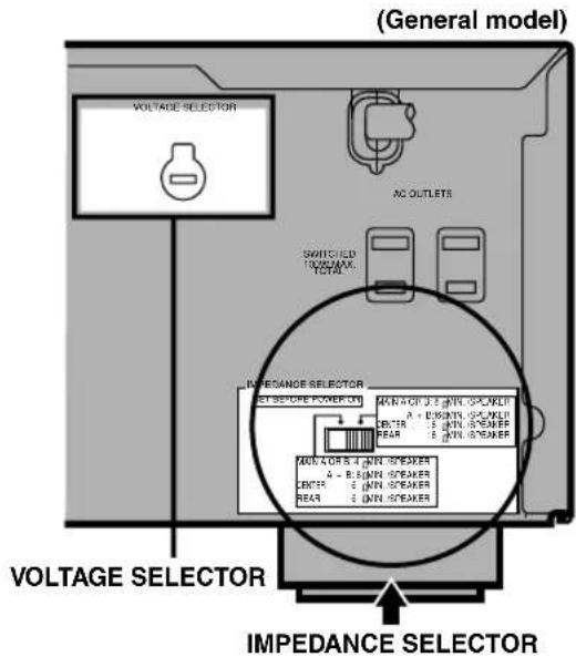
IMPEDANCE SELECTOR Switch
WARNING
Do not change the IMPEDANCE SELECTOR switch setting while the power of this unit is on, otherwise the unit may be damaged.
If this unit fails to turn on when STANDBY/ON (or POWER) is pressed, the IMPEDANCE SELECTOR switch may not be fully slid to either position. If so, slide the switch to either position fully when this unit is in the standby mode.
Select the left or right position according to the impedance of the speakers in your system. Be sure to move this switch only when this unit is in the standby mode.
| Switch position | Speaker Impedance level | |
| Left | Main | If you use one set of main speakers, the impedance of each speaker must be 4 Ω or higher. |
| If you use two sets of main speakers, the impedance of each speaker must be 8 Ω or higher. | ||
| Center | The impedance must be 6 Ω or higher. | |
| Rear | The impedance of each speaker must be 6 Ω or higher. | |
| Right | Main | If you use one set of main speakers, the impedance of each speaker must be 8 Ω or higher. |
| If you use two sets of main speakers, the impedance of each speaker must be 16 Ω or higher. | ||
| Center | The impedance must be 8 Ω or higher. | |
| Rear | The impedance of each speaker must be 8 Ω or higher. | |
■VOLTAGE SELECTOR (China and General models only)
The VOLTAGE SELECTOR on the rear panel of this unit must be set for your local main voltage BEFORE plugging into the AC main supply. Voltages are 110/120/220/240 V AC, 50/60 Hz.
Connecting the Power Supply Cords
After completing all connections, connect the AC power cord to an AC power outlet. Disconnect the AC power cord if you will not use this unit for a long period of time.
■AC OUTLET(S) (SWITCHED)
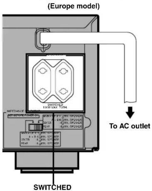
Europe, China and General models .... 2 OUTLETS U.K. model .... 1 OUTLET
Use these outlets to connect the power cords only from your audio/video components to this unit. The power to the AC OUTLET(S) is controlled by this unit's STANDBY/ON (or POWER and STANDBY). These outlets will supply power to any connected component whenever this unit is turned on. The maximum power (total power consumption of components) that can be connected to the AC OUTLET(S) is 100 W.
ON-SCREEN DISPLAY (OSD)
You can display the operation information for this unit on a video monitor. If you display the SET MENU and DSP program parameter settings on a monitor, it is much easier to see the available options and parameters than it is by reading this information on the front panel display.

- If a video source is being reproduced, the OSD is superimposed over the image.
- The OSD signal is not output to the REC OUT jack, and will not be recorded with any video signal.
- You can set the OSD to turn on (blue background) or off when a video source is not being reproduced (or the source component is turned off) by using “9 DISPLAY SET” on the SET MENU.
OSD Modes
You can change the amount of information the OSD shows.
Full display
This mode always shows the DSP program parameter settings on the video monitor.
Short display
This mode briefly shows the same contents as the front panel display at the bottom of the screen and then disappears.
Display off
This mode briefly shows the “DISPLAY OFF” message at the bottom of the screen and then disappears. Afterwards, no changes to operations appear on the monitor except those of the ON SCREEN button.
P01 CONCERT HALL
→ INIT. DLY....45ms ROOM SIZE 1.0 . LIVENESS ..... 5
P01 CONCERT HALL
Full display Short display

- When you choose the full display mode, INPUT / , VOLUME and some other types of operation information are displayed at the bottom of the screen in the same format as that for the front panel display.
- The SET MENU and test tone display appear regardless of the OSD mode.
Selecting the OSD Mode
When you turn on the power, the video monitor and front panel display show the level of the main volume for a few seconds and then switch to show the current DSP program.
2 Press ON SCREEN on the remote control repeatedly to change the display mode.
The OSD mode changes in the following order: full display, short display, and display off.
Notes
- If you choose a video input source that has a component connected to both the S VIDEO IN and composite VIDEO IN jacks, and both the S VIDEO OUT and composite VIDEO OUT jacks are connected to a video monitor, the video signal is output to both the S VIDEO OUT and VIDEO OUT jacks. However, the OSD is carried only on the S-video signal. If no video signal is input, the OSD is carried on both the S-video and composite video signals.
- If your video monitor is connected only to the COMPONENT VIDEO jacks of this unit, the OSD is not shown. Make sure to connect your video monitor to the COMPONENT VIDEO jacks and either VIDEO or S VIDEO jacks if you want to see the OSD.
- Playing back video software that has an anti-copy signal or video signals with a lot of noise may produce unstable images.
SPEAKER MODE SETTINGS
This unit is equipped with a main amplifier capable of handling 5.1 channel. Although up to 6 speakers can be connected, it is possible to select the speaker mode that gives the best sound field effect according to the number and size of speakers being used.
Before use, please set the speaker mode setting using "1 SPEAKER SET" on the SET MENU described on page 32.
Summary of SPEAKER SET Items 1A through 1E
| Item Description | Control value (default setting indicated in bold) | |
| 1A CENTER SP | Selects the output mode according to whether or not a center speaker is being used and its performance. | LRG/SML/NONE |
| 1B MAIN SP | Selects the output mode according to the performance of the main speakers. | LARGE/SMALL |
| 1C REAR L/R SP | Selects the output mode according to whether or not rear L/R speakers are being used and their performance. | LRG/SML/NONE |
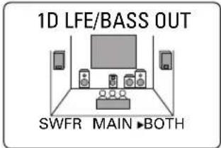
| 1D LFE/BASS OUT | Selects the speaker according to use for LFE signal output and low bass signal. | SWFR/MAIN/BOTH |
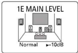
| 1E MAIN LEVEL Selects | the main speaker level. | Normal/-10 dB |
This section explains how to adjust the speaker output levels by using the test tone generator. When this adjustment is made, the output level heard at the listening position will be the same from each speaker. This is important for the best performance of the digital sound field processor, the Dolby Pro Logic decoder, Dolby Digital decoder and DTS decoder.
Note
- Since this unit cannot enter the test mode while headphones are connected to this unit, be sure to unplug the headphones from the PHONES jack when using the test tone.
Before You Begin

Press STANDBY/ON to turn on the power. Turn on the video monitor.


Press SPEAKERS A or B to select the main speakers to be used. If you are using two sets of the main speakers, press both A and B.

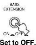
Set BASS and TREBLE on the front panel to the center position and set BASS EXTENSION to OFF.

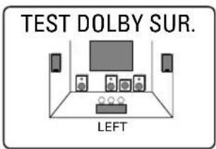
Using the Test Tone (TEST DOLBY SUR.)
The adjustment of each speaker output level should be made at your listening position with the remote control.
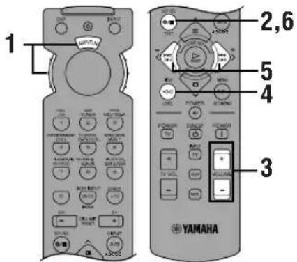

Set the selector dial to the AMP/TUN (or DSP/TUN) position.


Press TEST to output the test tone.


Adjust the volume so you can hear the test tone.
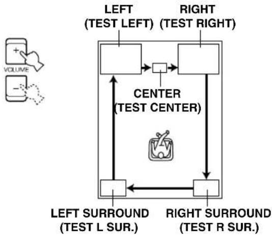
The test tone is heard from the left main speaker, center speaker, right main speaker, right rear speaker and left rear speaker in order. The tone is produced for 2.5 seconds each time.
flowchart
graph TD
    A["TEST LEFT"] --> B["TEST Center"]
    C["TEST RIGHT"] --> B
    B --> D["TEST L SUR."]
    B --> E["TEST R SUR."]
    D <--> E
    style B fill:#f9f,stroke:#333
    style D fill:#ccf,stroke:#333
    style E fill:#ccf,stroke:#333
The state of the test tone output is also shown on the monitor by an image of the audio listening room. This is convenient for adjusting each speaker level.

- If "1A CENTER SP" on the SET MENU is set to NONE, the center channel sound is automatically output from the left and right main speakers.
Note
- If the test tone cannot be heard, turn down the volume, set the unit in the standby mode and check the speaker connections.
4 Press LEVEL repeatedly to select the speaker to be adjusted.


- Once you press LEVEL, you can also select the speaker to be adjusted by pressing √. (Pressing ∧ changes the selection in the reverse order.)
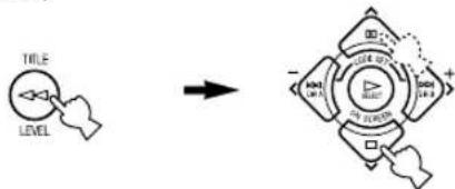
flowchart
graph LR
    A["TITLE"] --> B["LEVEL"]
    B --> C["→"]
    C --> D["Multi-Panel Diagram"]
    D --> E["Top Left"]
    D --> F["Top Right"]
    D --> G["Bottom Left"]
    D --> H["Bottom Right"]
5 Press repeatedly to adjust the output level of the currently selected speaker so that it becomes almost the same as that of the main speaker.

- While adjusting, the test tone is heard from the selected speaker.
- Repeat steps 4 and 5 to adjust the output levels of the center, left rear and right rear speakers.
6 When the adjustment is complete, press TEST.

The test tone stops and the current DSP program appears on the front panel display and on the video monitor.
Notes
- For details on adjusting the subwoofer speaker, refer to the effect speaker level adjustment described on page 38.
- After adjusting with the test tone, it is possible to adjust the speaker level to taste while listening to the playback of an actual source when using the effect speaker level adjustment described on page 38.

- You can increase the output levels of the effect speakers (center, left rear and right rear) to +10 dB. If the output level of these speakers is lower than that of the main speakers even after you have increased the output level of these speakers up to +10 dB, set “1E MAIN LEVEL” on the SET MENU to -10 dB. This setting decreases the main speaker output level to about one-third of the normal level. After you have set “1E MAIN LEVEL” on the SET MENU to -10 dB, adjust the levels for the center and rear speakers again.
BASIC PLAYBACK
When using the remote control, set the selector dial to the AMP/TUN position.
1 Press STANDBY/ON (or POWER) to turn on the power. Turn on the video monitor.
The front panel display and the video monitor show the level of the main volume for a few seconds and then switch to show the current DSP program.

Front panel
or

Remote control
2 Press SPEAKERS A or B to select the main speakers to be used.
If you are using two sets of main speakers, press both A and B.
Front panel
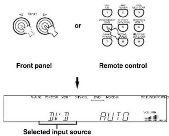
3 Press INPUT ◀/▷ repeatedly (or press one of the input selector buttons) to select the input source.
- The current input source is indicated on the front panel display with a cursor.
- The current input source name and input mode appear on the front panel display and on the video monitor for a few seconds.
flowchart
graph TD
    A["Input"] --> B["Front panel"]
    B --> C["Remote control"]
    C --> D["Selected input source"]

    subgraph Front panel
        E["1: Entertainment DVD"]
        F["2: TV/DVD"]
        G["3: Audio"]
        H["4: Radio"]
        I["5: Audio"]
        J["6: Radio"]
        K["7: Audio"]
        L["8: Audio"]
        M["9: Audio"]
    end

    subgraph Remote control
        N["V-AUX"]
        O["VCR2/VR"]
        P["VCR1"]
        Q["D-TV/CSL"]
        R["DVD"]
        S["MO/CD-R"]
        T["CDTUNER PHOND"]
    end

    style Front panel fill:#f9f,stroke:#333
    style Remote control fill:#ccf,stroke:#333
    style Selected input source fill:#fff,stroke:#000
Select this: To reproduce the signal from this component
PHONO: Turntable
CD: CD player
TUNER: AM/FM tuner
MD/CD-R: MD recorder/CD recorder/tape deck
DVD: DVD player
D-TV/CBL: TV/digital TV or cable TV/satellite tuner
VCR 1: Video cassette deck 1
VCR 2/DVR: Video cassette deck 2/digital video recorder
V-AUX: Another audio/video component (connected to the VIDEO AUX jacks on the front panel)
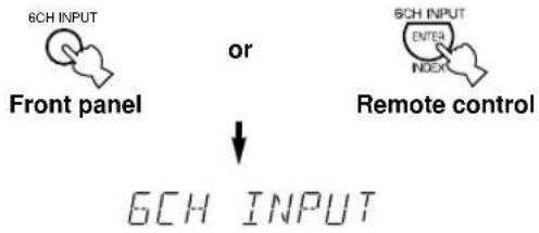
To select a source connected to the 6CH INPUT jacks
Press 6CH INPUT until "6CH INPUT" appears on the front panel display and on the video monitor.
flowchart
graph TD
    A["6CH INPUT"] --> B["Front panel"]
    C["6CH INPUT"] --> D["Remote control"]
    B --> E["6CH INPUT"]
    D --> E
    style A fill:#f9f,stroke:#333
    style C fill:#f9f,stroke:#333
    style B fill:#ccf,stroke:#333
    style D fill:#ccf,stroke:#333
Notes
- If "6CH INPUT" is shown on the front panel display and on the video monitor, no other source can be played. To select another input source with INPUT / (or the input selector buttons), press 6CH INPUT to turn off "6CH INPUT" from the front panel display and the video monitor.
- If you want to enjoy an audio source connected to the 6CH INPUT jacks together with a video source, first select the video source and then press 6CH INPUT.
4 Start playback (or select a broadcast station) on the source component.
Refer to the operation instructions for the component.
5 Adjust the volume to the desired output level.
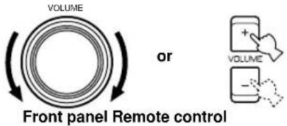
If desired, use BASS, TREBLE and BASS EXTENSION etc. These controls are only effective for sound from the main speakers.
Note
- If the component connected to the VCR 1 OUT, VCR 2/DVR OUT and MD/CD-R OUT jacks is turned off, the reproduced sound may be distorted or the volume may be lowered. In these cases, turn on the component.
6 Use the digital sound field processor.
See "Selecting a Sound Field Program".
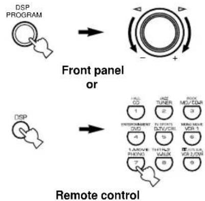
flowchart
graph TD
    A["DSP PROGRAM"] --> B["Front panel or"]
    B --> C["Remote control"]
    subgraph Control Path
        D["Hall CO 1"] --> E["SWITCHENMENT CO 2"]
        F["WAZ TUNER 2"] --> G["THYFORD CTN/COL 3"]
        H["RICK MO/COL 3"] --> I["MEDIUM VOR 1"]
        J["1,4,5,6"] --> K["THYFORD VALK 5"]
        L["7,8"] --> M["REMARK VALK 6"]
        N["9"] --> O["REMARK VALK 7"]
    end
■ To mute the sound
Use this when you want to temporarily mute audio output.
Press MUTE on the remote control.
To restore the audio output to the previous volume level, press MUTE again.


- You can also cancel mute to press any operation buttons such as VOLUME +/-.
- During muting, "MUTE ON" appears on the front panel display and on the video monitor.
■ When you have finished using this unit
Press STANDBY/ON (or STANDBY) to set this unit in the standby mode.
■ Notes on the digital signal
The digital input jacks of this unit can also handle 96-kHz sampling digital signals. (To utilize this, use a source that supports 96-kHz sampling digital signals and set the player for digital output. Refer to the operation instructions for the player.) Note the following when a 96-kHz sampling digital signal is input to this unit:
- The following indication will appear on the front panel display.
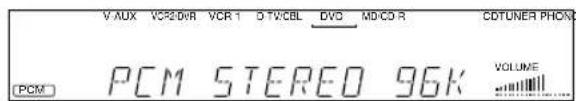
- DSP programs cannot be selected. Sound will be output as normal 2-channel stereo sound from only the left and right main speakers.
Note
- If "1B MAIN SP" on the SET MENU is set to SMALL and "1D LFE/BASS OUT" is set to SWFR, or "1D LFE/BASS OUT" is set to BOTH, the sound is also output from the subwoofer.
- Adjustment of the speaker output level (except for subwoofer output level) described on page 38 cannot be made.
■BGV (background video) function
The BGV function allows you to combine a video image from a video source with a sound from an audio source. (For example, you can listen to classical music while you are watching a video.)
Select a source from the video group and then select a source from the audio group with the input selector buttons on the remote control. The BGV function does not work if you select the sources with INPUT ◀/▷ on the front panel.
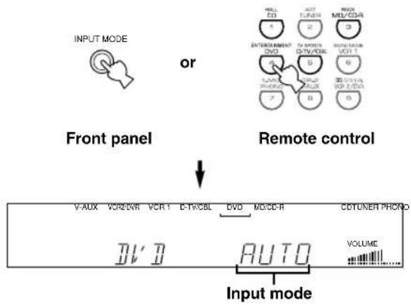
Input Modes and Indications
When using the remote control, set the selector dial to the AMP/TUN position.
This unit comes with various input jacks. If your component is connected to more than one type of input jack, you can set the priority of the input signal.
Press INPUT MODE (or the input selector button that you have pressed to select the input source on the remote control) repeatedly until the desired input mode is shown on the front panel display and on the video monitor.
flowchart
graph TD
    A["Input mode"] --> B["V-AUX"]
    A --> C["VCR2DVR"]
    A --> D["VCR1"]
    A --> E["C-TV/CBL"]
    A --> F["DVD"]
    A --> G["M/CE-R"]
    A --> H["CDTUNER PHONE"]
    A --> I["VOLUME"]
    J["Front panel"] --> K["OR"]
    K --> L["ENTERTAINMENT"]
    K --> M["EXTRUSTMENT"]
    K --> N["MOHNSURANCE"]
    K --> O["MOHNSURANCE"]
    K --> P["MOHNSURANCE"]
    K --> Q["MOHNSURANCE"]
    K --> R["MOHNSURANCE"]
    K --> S["MOHNSURANCE"]
    K --> T["MOHNSURANCE"]
    K --> U["MOHNSURANCE"]
    K --> V["MOHNSURANCE"]
    K --> W["MOHNSURANCE"]
    K --> X["MOHNSURANCE"]
AUTO: In this mode, the input signal is
automatically selected in the following order:
1) Dolby Digital or DTS signal
2) Digital (PCM) signal
3) Analog signal
DTS: In this mode, only the digital input signal encoded with DTS is selected even if another signal is input at the same time.
ANLG (ANALOG): In this mode, only the analog input signal is selected even if a digital signal is input at the same time.
Notes
- If digital signals are input from both the COAXIAL and OPTICAL jacks, the digital signal from the COAXIAL jack is selected.
- When AUTO is selected, this unit automatically determines the type of signal. If this unit detects a Dolby Digital or DTS signal, the decoder automatically switches to the appropriate setting and reproduces 5.1 channel source.
- The sound output may be interrupted for some LD players and DVD players in the following situation: When the input mode has been set to AUTO and a search is performed while playing the source encoded with a Dolby Digital or DTS signal, the sound may delay for a moment when playback is resumed.
- Depending on the LD player, playback may not be made when playing an LD that is not digitally recorded with the input mode set to AUTO. If this happens, set the input mode to ANALOG.
■Notes on playing a source encoded with a DTS signal
- If the digital output data of the player has been processed in any way, you may not be able to perform DTS decoding even if you make a digital connection between this unit and the player.
- If you play a source encoded with a DTS signal and set the input mode to ANALOG, this unit reproduces the noise of an unprocessed DTS signal. When you want to play a DTS source, be sure to connect the source to a digital input jack and set the input mode to AUTO or DTS.
- If you switch the input mode to ANALOG while playing a source encoded with a DTS signal, this unit reproduces no sound.
- The following phenomena may occur if the input mode is set to AUTO when playing back source encoded with a DTS signal.
- If you continue to play a source encoded with a DTS signal, this unit automatically switches to the “DTS-decoding” mode to prevent noise from being generated during subsequent operation. (The “dts” indicator lights up on the front panel display.) The “dts” indicator may flash immediately after playback of a source encoded with a DTS signal has finished. Only a source encoded with a DTS signal can be played back while this indicator is flashing. (The indicator will flash for less than a minute.) If you want to play a normal PCM source soon, set the input mode back to AUTO.
- The “dts” indicator may flash when a search or skip operation is performed. If this status continues for a certain length of time, the unit will automatically switch from the “DTS-decoding” mode to PCM digital signal input mode and the “dts” indicator will go out.
Selecting a Sound Field Program
You can enhance your listening experience by selecting a DSP program. For details about each program, see "SOUND FIELD PROGRAM".
■On the remote control
1 Press DSP.
The indicator lights up for about 3 seconds.


- If the selector dial is set to the DSP/TUN position, skip this step.
2 Use the numeric buttons to select the desired program before the indicator goes off.
- For example, to select the sub-program "SPECTACLE", press MOVIE THEATER 1 repeatedly.
- The name of the selected program appears on the front panel display and on the video monitor.
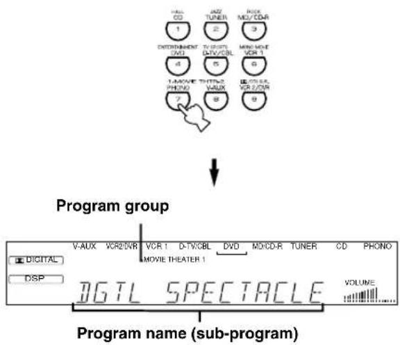
flowchart
graph TD
    A["Program group"] --> B["Program name (sub-program)"]
    B --> C["1: V-AUX"]
    B --> D["2: VCR2/VR"]
    B --> E["3: VCR 1"]
    B --> F["4: D-TV/3BL"]
    B --> G["5: DVD"]
    B --> H["6: MCD/RDAR"]
    B --> I["7: MCD/RDAR"]
    B --> J["8: MCD/RDAR"]
    B --> K["9: MCD/RDAR"]
■On the front panel
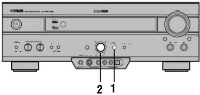
1 Press DSP PROGRAM.

2 Turn the multi jog knob to select the program.
The name of the selected program appears on the front panel display and on the video monitor.
Notes
- Choose a DSP program based on your listening preference, and not on the name of the program. The acoustics of your listening room affect the DSP program. Minimize the sound reflections in your room to maximize the effect created by the program.
- When you select an input source, this unit automatically selects the last DSP program used with that source.
- When you set this unit in the standby mode, the current source and DSP program are memorized and are automatically selected when you turn on the power again.
- If a Dolby Digital or DTS signal is input when the input mode is set to AUTO, the DSP program automatically switches to the appropriate decoding program.
- When a monaural source is being played with PRO LOGIC/NORMAL or PRO LOGIC/ENHANCED, no sound will be heard from the main speakers and the rear speakers. Sound can only be heard from the center speaker. However, if "1A CENTER SP" on the SET MENU is set to NONE, the center channel sound is output from the main speakers.
- When a source connected to the 6CH INPUT jacks of this unit is selected, the digital sound field processor cannot be used.
- When 96-kHz sampling digital signals are input to this unit, the DSP program cannot be selected. In this case, the sound is reproduced as normal 2-channel stereo.
■Virtual CINEMA DSP and SILENT CINEMA
Virtual CINEMA DSP
Virtual CINEMA DSP allows you to enjoy the sound field effects of the DSP program without rear speakers. Using YAMAHA original technology, natural surround reproduction is possible through the generation of a virtual speaker.
The sound field processing is changed to the Virtual CINEMA DSP mode by setting “1C REAR L/R SP” on the SET MENU to NONE. Virtual CINEMA DSP is performed by using the main speakers.
Note
- This unit is not set in the Virtual CINEMA DSP mode even if "1C REAR L/R SP" is set to NONE in the following cases:
- when the 5CH STEREO, PRO LOGIC/NORMAL, DOLBY DIGITAL/NORMAL or DTS/NORMAL program is selected;
- when the sound effect is turned off;
- when 6CH INPUT is selected as the input source;
- when 96-kHz sampling digital signals are input to this unit;
- when the Dolby Digital KARAOKE source is played;
- when using the test tone; or
- when connecting the headphones (you will hear SILENT CINEMA).
SILENT CINEMA
SILENT CINEMA allows you to enjoy the realistic feel of the DSP program while using headphones. This feature delivers powerful surround reproduction just as if listening through the speakers.
You can listen to SILENT CINEMA by connecting your headphones to the PHONES jack while the effect speakers are on.
Normal Stereo Reproduction
Press EFFECT to turn off the sound effect for normal stereo reproduction.
Press EFFECT again to turn the sound effect back on.
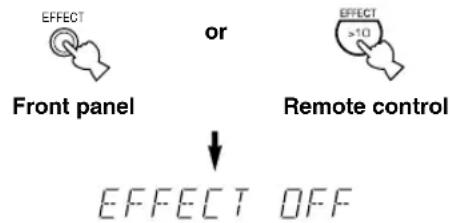

- If the selector dial is set to a position other than the DSP/TUN position, first press DSP and then EFFECT on the remote control.
Notes
- If you turn off the sound effect, no sound is output from the center and rear speakers.
- If you turn off the sound effect while a Dolby Digital or DTS signal is being output, the dynamic range of the signal is automatically compressed and the sounds of the center and rear speaker channels are mixed and output from the main speakers.
- The volume may be greatly reduced when you turn off the sound effect or if you set “6 D-RANGE” on the SET MENU to MIN. In this case turn on the sound effect.
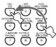
BASIC RECORDING
Recording adjustments and other operations are performed from the recording components. Refer to the operation instructions for these components.
1 Turn on the power to the unit and all connected component.
2 Select the source component you want to record from.
Front panel
or
Remote control
3 Start playback (or select a broadcast station) on the source component.
4 Start recording on the recording component.
Notes
- Do a test recording before you start an actual recording.
- When this unit is set in the standby mode, you cannot record between other components connected to this unit.
- The setting of BASS, TREBLE, BASS EXTENSION, VOLUME, “2 L/R BALANCE” on the SET MENU and DSP programs does not affect the recorded material.
- A source connected to the 6CH INPUT jacks of this unit cannot be recorded.
- S-video and composite video signals pass independently through this unit's video circuits. Therefore, when recording or dubbing video signals, if your video source component is connected to provide only an S-video (or only a composite video) signal, you can record only an S-video (or only a composite video) signal by your VCR.
- A given input source is not output on the same REC OUT channel. (For example, the signal input from VCR 1 IN is not output on VCR 1 OUT.)
- Check the copyright laws in your country to record from records, CDs, radio, etc. Recording of copyrighted material may infringe copyright laws.
If you playback a video source that uses scrambled or encoded signals to prevent it from being dubbed, the picture itself may be disturbed due to those signals.
■Special considerations when recording DTS software
The DTS signal is a digital bitstream. Attempting to digitally record the DTS bitstream will result in noise being recorded. Therefore, if you want to use this unit to record sources that have DTS signals recorded on them, the following considerations and adjustments need to be made.
For DVDs and CDs encoded with DTS
Only 2-channel analog audio signals may be recorded. Set the DVD player (or CD player) as described in the player's operation instructions so that the audio signals are output from the player's analog outputs.
SET MENU
The SET MENU consists of 10 items including the speaker mode setting features. Use the SET MENU to enjoy the optimum audio/video playback for your system.

- You can adjust the items on the SET MENU while playing a source.
- We recommend that you adjust the items on the SET MENU while using a video monitor. It is easier to see the video monitor than it is to see the front panel display on this unit while adjusting the items.
Note
- The indication on the front panel display is the abbreviation of the OSD.
1 SPEAKER SET
1A CENTER SP
1B MAIN SP
1C REAR L/R SP
1D LFE/BASS OUT
1E MAIN LEVEL
2 L/R BALANCE
3 HP TONE CTRL
4 I/O ASSIGNMENT
4A CMPNT-V INPUT
4B OPTICAL OUT
4C OPTICAL IN
4D COAXIAL IN
5 INPUT MODE
6 DOLBY D. SET
LFE LEVEL
D-RANGE
7 DTS SET
8 SP DELAY TIME
9 DISPLAY SET
BLUE BACK
OSD SHIFT
DIMMER
10 MEMORY GUARD
Adjusting the Items on the SET MENU
Adjustment should be made with the remote control.
Notes
- Some items require extra steps to change to the desired setting.
- SET MENU and the multi jog knob on the front panel can also be used to make these adjustments.
1 Set the selector dial to the AMP/TUN (or DSP/TUN) position.

2 Press SET MENU to enter the SET MENU.

SET MENU 1/3
→1 SPEAKER SET 2 L/R BALANCE 3 HP TONE CTRL 4 I/O ASSIGNMENT ▲/▼: Up/Down -/+ : Enter
3 Press ∧√ repeatedly to select the item (1 to 10) you want to adjust.
flowchart
graph TD
    A["Device"] --> B["Control Unit"]
    B --> C["Display"]
    C --> D["Arrow Right"]
    style A fill:#f9f,stroke:#333
    style B fill:#ccf,stroke:#333
    style C fill:#cfc,stroke:#333
    style D fill:#fcc,stroke:#333
SET MENU 1/3
1 SPEAKER SET 2 L/R BALANCE 3 HP TONE CTRL →4 I/O ASSIGNMENT ▲/▼ : Up/Down -/+ : Enter

- By pressing SET MENU (or SET MENU on the front panel) repeatedly, you can select items in the same order as when pressing √.
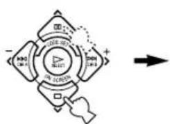
4 Press < or > once to enter the setup mode of the selected item.
The last setting you adjusted appears on the video monitor or on the front panel display.
![4A CMPNT-V INPUT →[A]…… DVD [B]…… D-TV/CBL](/content/2026/02/379921/images/b9a948dd5c4bd821a6030ef34d549baf4e1ddd2169767129ee05fcc7202e4066.jpg)

- When making adjustments through the front panel, turn the multi jog knob one step to either the left or the right to enter setup mode for the selected item.
Depending on the item, press ∧∨∨ to select a sub item.
- When making adjustments through the front panel, press SET MENU.
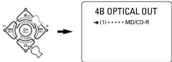
5 Press < / > repeatedly to change the setting of the item.
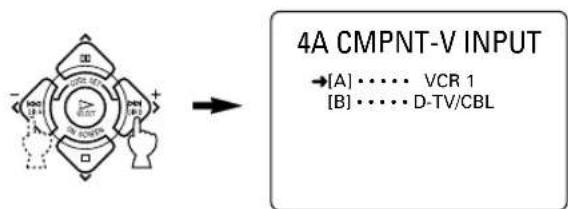
flowchart
graph LR
    A["4A CMPNT-V INPUT"] --> B["VCR 1"]
    A --> C["D-TV/CBL"]

- When making adjustments through the front panel, turn the multi jog knob to change the settings.
6 Press ∧√ repeatedly until the current DSP program appears or simply press one of the DSP program group button to exit from the SET MENU.
flowchart
graph TD
    A["Device with DSP"] --> B["Control Logic"]
    B --> C["Display/Control Logic"]
    C --> D["Output: Multi-channel Display/Control Logic"]
    style A fill:#f9f,stroke:#333
    style B fill:#ccf,stroke:#333
    style C fill:#cfc,stroke:#333
    style D fill:#fcc,stroke:#333

- When operating through the front panel, press SET MENU repeatedly until the DSP program name appears to exit from the SET MENU.
Memory back-up
The memory back-up circuit prevents the stored data from being lost even if this unit is set in the standby mode, the power cord is disconnected from the AC outlet, or the power supply is temporarily cut due to power failure. However, if the power is cut for more than one week, the settings of the SET MENU you adjusted will return to the factory settings. If so, adjust the items again.
1 SPEAKER SET (speaker mode settings)
Use this feature to select suitable output modes for your speaker configuration.
Notes
- When 96-kHz sampling digital signals are input to this unit, level adjustments in items 1B, 1D and 1E are possible, but those in items 1A, 1C are not affected.
- When 6CH INPUT is selected as the input source, level adjustments in items 1A through 1E are not affected.
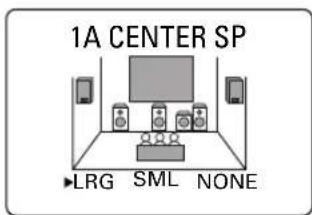
■ 1A CENTER SP (center speaker mode)
By adding a center speaker to your speaker configuration, the unit can provide good dialog localization for many listeners and superior synchronization of sound and images. The OSD shows a large, small or no center speaker depending on how you set this item.
Choices: LRG (large), SML (small), NONE Initial setting: LRG
LRG
Select this if you have a large center speaker. The entire range of the center channel signal is directed to the center speaker.
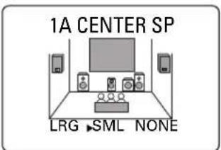
SML
Select this if you have a small center speaker. The low-frequency signals (90 Hz and below) of the center channel are directed to the speakers selected with "1D LFE/BASS OUT".
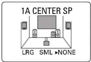
NONE
Select this if you do not have a center speaker. All of the center channel signals are directed to the left and right main speakers.
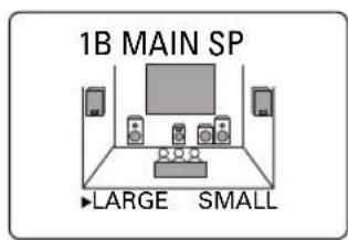
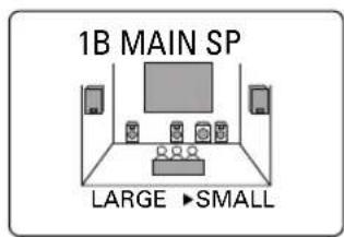
■1B MAIN SP (main speaker mode)
The OSD shows large or small main speakers depending on how you set this item.
Choices: LARGE, SMALL
Initial setting: LARGE
LARGE
Select this if you have large main speakers. The entire range of the left and right main channel signal is directed to the left and right main speakers.
SMALL
Select this if you have small main speakers. The low-frequency signals (90 Hz and below) of the main channel are directed to the speakers selected with "1D LFE/BASS OUT".
Note
- When you select MAIN for "1D LFE/BASS OUT", the low-frequency signals (90 Hz and below) of the main channel are directed to the main speakers even if you select SMALL for the main speaker mode.
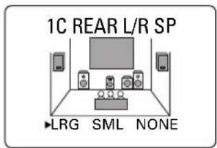
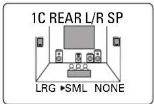
■1C REAR L/R SP (rear speaker mode)
The OSD shows large, small or no rear speakers depending on how you set this item.
Choices: LRG (large), SML (small), NONE Initial setting: LRG
LRG
Select this if you have large left and right rear speakers or if a rear subwoofer is connected to the rear speakers. The entire range of the rear channel signal is directed to the left and right rear speakers.
SML
Select this if you have small left and right rear speakers. The low-frequency signals (90 Hz and below) of the rear channel are directed to the speakers selected with "1D LFE/BASS OUT".
NONE
Select this if you do not have rear speakers.
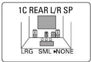

- This unit is set in the Virtual CINEMA DSP mode by selecting NONE for "1C REAR L/R SP".
SET MENU
■1D LFE/BASS OUT (bass out mode)
LFE signals carry low-frequency effects when this unit decodes a Dolby Digital or DTS signal. Low-frequency signals are defined as 90 Hz and below.
Choices: SWFR (subwoofer), MAIN, BOTH Initial setting: BOTH
SWFR
Select this if you use a subwoofer. The LFE signals are directed to the subwoofer.
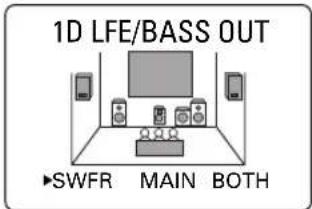
MAIN
Select this if you do not use a subwoofer. The LFE signals are directed to the main speakers.
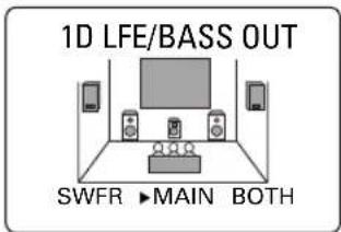
BOTH
Select this if you use a subwoofer and you want to mix the main channel low-frequency signals with the LFE signals.
Notes
- When playing a 2-channel source (CD, MD, tape, video cassette etc.), select the BOTH position to direct low bass signals (below 90 Hz) to the SUBWOOFER jack.
- When you select SMALL (SML) for items 1A, 1B and 1C, the low-frequency signals (90 Hz and below) from those channels are added to the LFE and output to the subwoofer.
■1E MAIN LEVEL (main level mode)
Change this setting if you cannot match the output level of the center and rear speakers with the main speakers because of the unusually high-efficiency performance of the main speakers.
Choices: Normal, -10 dB Initial setting: Normal
Normal
Normally select this setting.
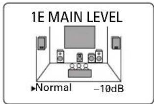
-10 dB
Select this if you cannot match the output level of your effect speakers with that of your main speakers when using the test tone. This setting decreases the main speaker output level to about one-third of the normal level.
2 L/R BALANCE (balance of the left and right main speakers)
Use this feature to adjust the balance of the output level from the left and right main speakers.
Control range: 10 for L/R Initial setting: 0
Press > to decrease the output level for the left main speaker. Press < for the right main speaker.
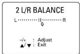
Note
- The L/R BALANCE setting also applies to when headphones are being used.
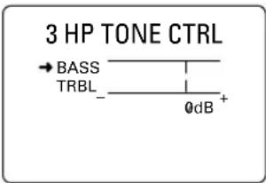
3 HP TONE CTRL (headphone tone control)
Use this feature to adjust the level of the bass and treble when you use your headphones.
Control range (dB): -6 to +3
Initial setting: 0 dB for both BASS and TRBL (treble)
4 I/O ASSIGNMENT
It is possible to assign jacks according to the component to be used if this unit's COMPONENT VIDEO input jack or DIGITAL INPUT/OUTPUT jack settings (component names for jacks) differ from that component. This makes it possible to change the jack assignment and effectively connect more component.
Once you assign, you can select that component with INPUT ◀/▷ (or the input selector buttons).
■4A CMPNT-V INPUT (for the COMPONENT VIDEO jacks)
Initial settings: [A] DVD
[B] D-TV/CBL
4A CMPNT-V INPUT
→[A] ····· DVD [B] ····· D-TV/CBL
■4B OPTICAL OUT (for the OPTICAL OUTPUT jack)
Initial setting: (1) MD/CD-R
4B OPTICAL OUT
■4C OPTICAL IN (for the OPTICAL INPUT jacks)
Initial settings: (2) MD/CD-R
(3) DVD
(4) D-TV/CBL
4C OPTICAL IN
■4D COAXIAL IN (for the COAXIAL INPUT jack)
Initial setting: (5) CD
4D COAXIAL IN
→(5) · · · · CD
Note
- You cannot select an item more than once for the same type of jack.
5 INPUT MODE (initial input mode)
Use this feature to designate the input mode when turning on the power of this unit with the source component connected to more than one type of input jacks.
Choices: AUTO, LAST
Initial setting: AUTO
5 INPUT MODE
▶ AUTO LAST
-/+ : Select ▲/▼Exit
AUTO
Select this to allow this unit to automatically detect the type of input signal and select the appropriate input mode.
LAST
Select this to set this unit to automatically select the last input mode used for that source.
6 DOLBY D. SET (Dolby Digital set)
This setting is effective only when this unit decodes Dolby Digital signals.
6 DOLBY D. SET
Use this feature to adjust the output level of the LFE (low-frequency effect) channel when playing back a Dolby Digital signal. The LFE signal carries the low-frequency special effect sound which is only added to certain scenes.
Control value (dB): -20 to 0
Initial setting: 0 dB
Notes
- Adjust the LFE level according to the capacity of your subwoofer.
- Normally, around -6 dB to -8 dB is most suitable for listening at home.
■D-RANGE (dynamic range)
Use this feature to adjust the dynamic range (the difference between the maximum level and the minimum level of sounds).
Choices: MAX, STD (standard), MIN
Initial setting: MAX
- Select MAX for feature films.
- Select STD for general use.
- Select MIN for listening to sources at an extremely low volume level.
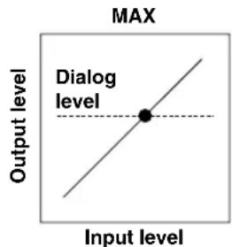
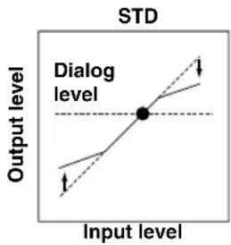
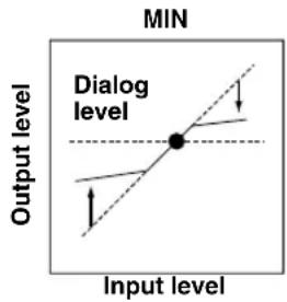
Note
- When you select MIN, the sound output may be faint because some Dolby Digital signals are not compatible with the minimum-level dynamic range. In this case, select MAX or STD.
7 DTS SET (DTS LFE level)
This setting is effective only when this unit decodes DTS signals.
Use this feature to adjust the output level of the LFE (low-frequency effect) channel when playing back a DTS signal. The LFE signal carries the low-frequency special effect sound which is only added to certain scenes.
Control range (dB): -10 to +10
Initial setting: 0 dB
7 DTS SET
- Adjust the LFE level according to the capacity of your subwoofer.
8 SP DELAY TIME
Use this feature to adjust the delay of the center channel sound. This feature works when this unit decodes a Dolby Digital or DTS signal. Ideally, the center speaker should be the same distance from the listening position as the left and right main speakers. However, in most home situations, the center speaker is placed in line with the main speakers. By delaying the sound from the center speaker, the apparent distance from the center speaker to the listening position can be adjusted to make it seem the same as the distance between the left and right main speakers to the listening position. Adjusting the delay time for the center speaker is especially important for giving depth to the dialog.
Control range (ms): 0 to 5
Initial setting: 0 ms
8 SP DELAY TIME
Center speaker image
flowchart
graph TD
    L["Node L"] --> C["C"]
    C --> R["R"]
    C --> RL["Node RL"]
    C --> RR["Node RR"]
    C -.-> C
    C -.-> RL
    C -.-> RR
    style C fill:#f9f,stroke:#333
    style L fill:#ccf,stroke:#333
    style C fill:#cfc,stroke:#333
    style R fill:#fcc,stroke:#333
    style RL fill:#cff,stroke:#333
    style RR fill:#ffc,stroke:#333

- Increasing the delay by 1 ms simulates moving the speaker about 30cm (one foot) farther away from the actual position of the center speaker.
9 DISPLAY SET
9 DISPLAY SET
→BLUE BACK ... AUTO
Selecting AUTO for the on-screen display setting displays a blue background when there's no video signal input.
Nothing is displayed on the screen including the on-screen display if OFF is selected.
Initial setting: AUTO
■OSD SHIFT (OSD off-set position)
This setting is used to adjust the vertical position of the OSD.
Control range: +5 (downward) to -5 (upward)
Initial setting: 0
Press > to lower the position of the OSD.
Press < to raise the position of the OSD.
DIMMER
You can adjust the brightness of the front panel display.
Control range: -4 to 0
Initial setting: 0
10 MEMORY GUARD
Use this feature to prevent accidental changes to DSP program parameter values and other settings on this unit.
Choices: ON, OFF
Initial setting: OFF
10 MEMORY GUARD
▶ OFF
ON
-/+
Select
Exit
Select ON to protect the following features:
- DSP program parameters
- All SET MENU items
• Center, rear speakers and subwoofer levels
• The on-screen display (OSD) mode
Notes
- When “10 MEMORY GUARD” is set to ON, you cannot use the test tone.
- When "10 MEMORY GUARD" is set to ON, you cannot select any other SET MENU items.
You can adjust the output level of each effect speaker (center, left and right rear and subwoofer) while listening to a music source.
Adjustment should be made with the remote control.
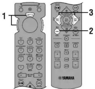

Set the selector dial to the AMP/TUN (or DSP/TUN) position.


Press LEVEL repeatedly to select the speaker(s) you want to adjust.
Each time you press LEVEL, the selected speaker changes and appears on the front panel display and on the video monitor as follows: center, right rear, left rear and subwoofer.
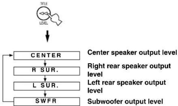
flowchart
graph TD
    A["TITLE\nLEVEL"] --> B["CENTER"]
    B --> C["R SUR."]
    C --> D["L SUR."]
    D --> E["SWFR"]
    style A fill:#f9f,stroke:#333
    style B fill:#ccf,stroke:#333
    style C fill:#cfc,stroke:#333
    style D fill:#fcc,stroke:#333
    style E fill:#cff,stroke:#333

- Once you press LEVEL, you can also select the speaker(s) to be adjusted by pressing ∨. (Pressing ∧ changes the selection in the reverse order.)
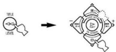
flowchart
graph TD
    A["Hand pointing at 'TITLE' symbol"] --> B["Arrow pointing right"]
    B --> C["Diagram with directional arrows and labels: 'OFF', 'ON', 'DOWN', 'OK', 'SOLD'"]

Press < / > to adjust the speaker output level.
- The control range for the center or left and right rear speakers is from +10 dB to -10 dB.
- The control range for the subwoofer is from 0 dB to -20 dB.

Notes
- If the speaker output mode is set to NONE, the output level of that speaker cannot be adjusted.
- When you adjust the output level with LEVEL, the settings you made with the test tone will be changed.
• To adjust speakers other than the subwoofer, the adjusting procedure using the test tone on page 22 is recommended.
Memory back-up
The memory back-up circuit prevents the stored data from being lost even if this unit is set in the standby mode, the power cord is disconnected from the AC outlet, or the power supply is temporarily cut due to power failure. However, if the power is cut for more than one week, the output level of the effect speakers you adjusted will return to the factory settings. If so, adjust the output level again.
SLEEP TIMER
Use this feature to automatically set this unit in the standby mode after the amount of time you have set. The sleep timer is useful when you are going to sleep while this unit is playing or recording a source. The sleep timer also automatically turns off the external components connected to AC OUTLET(S).
The sleep timer can only be set with the remote control.
Setting the Sleep Timer
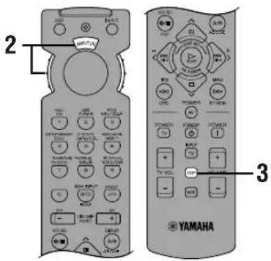
1 Select a source and start playback on the source component.
2 Set the selector dial to a position other than the TV position.

3 Press SLEEP repeatedly to set the amount of time before this unit automatically turns off.

Each time you press SLEEP, the front panel display changes as shown below.
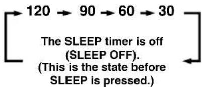
flowchart
graph LR
    A["120"] --> B["90"]
    B --> C["60"]
    C --> D["30"]
    D --> E["The SLEEP timer is off (SLEEP OFF). (This is the state before SLEEP is pressed.)"]
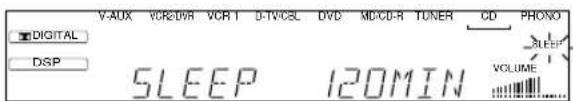
4 The "SLEEP" indicator soon lights up on the front panel display after the sleep timer has been set.
The display then returns to the previous indication.
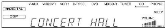
Canceling the Sleep Timer
Press SLEEP repeatedly until "SLEEP OFF" appears on the front panel display.
After a few seconds, "SLEEP OFF" disappears, the "SLEEP" indicator goes off and the display returns to the previous indication.


- The sleep timer setting can also be canceled by setting this unit in the standby mode by using STANDBY on the remote control (or STANDBY/ON on the front panel) or by disconnecting the AC power cord from the AC outlet.
REMOTE CONTROL FEATURES
It is possible to control this unit and other YAMAHA A/V components using the remote control supplied with this unit. It is also possible to control components from other manufacturers (or some YAMAHA components) by setting the proper manufacturer code (a signal assigned to each manufacturer and component).
Note
- For the notes on batteries, operating distance and names and functions of the remote control, refer to each description in this manual.
Selector Dial
Select the component (position) to be controlled by the remote control. For example, if the CD position is selected, the remote control is set in the CD operation mode, allowing the CD player to be controlled. When turning the selector dial, the position changes as follows:
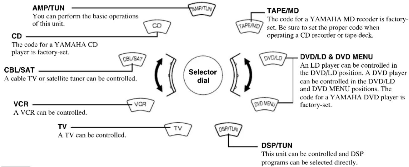
flowchart
graph TD
    A["CD"] -->|The code for a YAMAHA CD player is factory-set.| B["AMP/TUN"]
    B --> C["You can perform the basic operations of this unit."]
    C --> D["CD"]
    D --> E["Selection dial"]
    E --> F["TAPE/MD"]
    F --> G["The code for a YAMAHA MD recorder is factory-set. Be sure to set the proper code when operating a CD recorder or tape deck."]
    E --> H["DVD/LD & DVD MENU"]
    H --> I["An LD player can be controlled in the DVD/LD position. A DVD player can be controlled in the DVD/LD and DVD MENU positions. The code for a YAMAHA DVD player is factory-set."]
    E --> J["DSP/TUN"]
    J --> K["This unit can be controlled and DSP programs can be selected directly."]
    E --> L["VCR"]
    L --> M["A VCR can be controlled."]
    M --> N["TV"]
    N --> O["A TV can be controlled."]
    O --> P["CD/SAT"]
    P --> Q["CBL/SAT"]
    Q --> R["Selector dial"]
    R --> S["Tape/MD"]
    S --> T["TAPE/MD"]
    T --> U["DVD/LD & DVD MENU"]
    U --> V["DVD MENU"]
    V --> W["DSP/TUN"]
Notes
- The general operational buttons on the remote control differ depending on the position of the selector dial. See the following pages for details.
- When shipped from the factory, the YAMAHA manufacturer codes listed on page 46 are set for each dial position. If unable to operate your YAMAHA A/V component, please try using another YAMAHA code.
Commonly Used Buttons in Any Position of the Selector Dial
Regardless of the position of the selector dial, you can control this unit and your TV with the following buttons.
Note
- You have to set up the code for your TV in the TV position before you can control the TV.
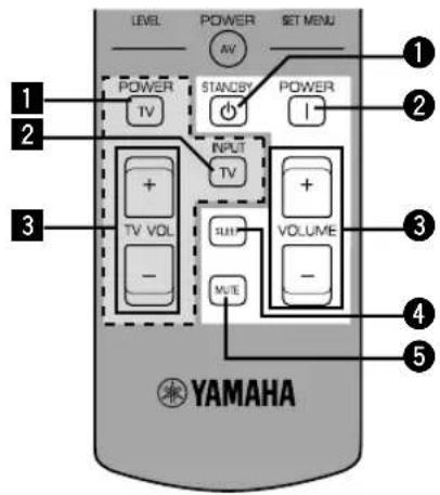
■Controlling this unit
See "Remote Control".
1STANDBY
②POWER
③VOLUME +/-
④SLEEP
Note
- If you have set up the code for your TV and set the selector dial to the TV position, this button is used to set the sleep timer for the TV.
⑤MUTE
Note
- If you have set up the code for your TV and set the selector dial to the TV position, this button is used to mute the TV sound.
■Controlling your TV
1 TV POWER
2 TV INPUT
3 TV VOLUME +/-
Controlling the Components Connected to This Unit
The example below describes the procedure for controlling a YAMAHA CD player.
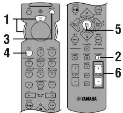
1 Set the selector dial to the CD position.

2 Turn on the power.

3 Press INPUT. The indicator lights up for about 3 seconds.

4 Press CD while the indicator is lit.

5 Press ▷. See “Button Names and Functions in Eash Position” for the CD player operation buttons.
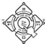
6 Adjust the volume.
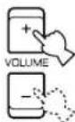
If you set the remote control with the manufacturer codes listed from page i at the end of this manual, you can control other brands of components. See "Setting the Manufacturer Codes" for details.
Button Names and Functions in Each Position
■TAPE/MD position (tape deck, MD recorder or CD recorder)
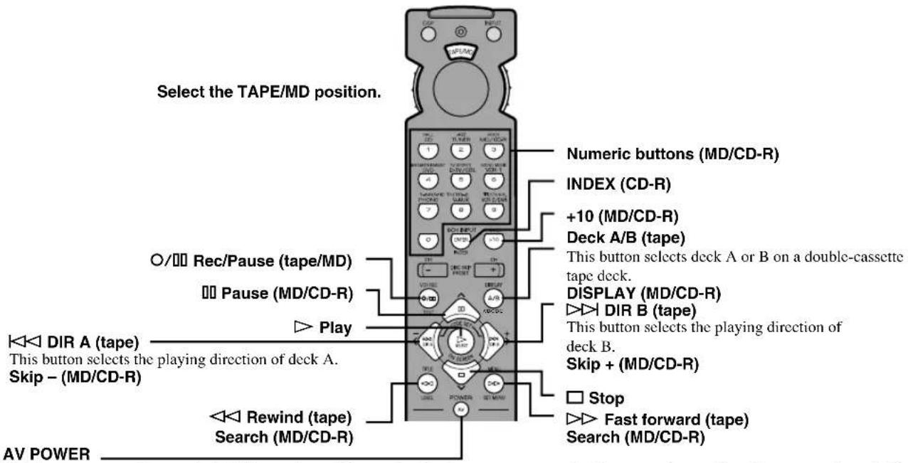
This button turns on the tape deck, MD recorder or CD recorder that has a remote control with a power button if you have set up the code for another manufacturer.
■CD position

- The dark-shaded buttons do not function even if you have set up the manufacturer code.
- Some of them may not function depending on the component you have. In this case, use the original remote control supplied with your component.
■DVD/LD position
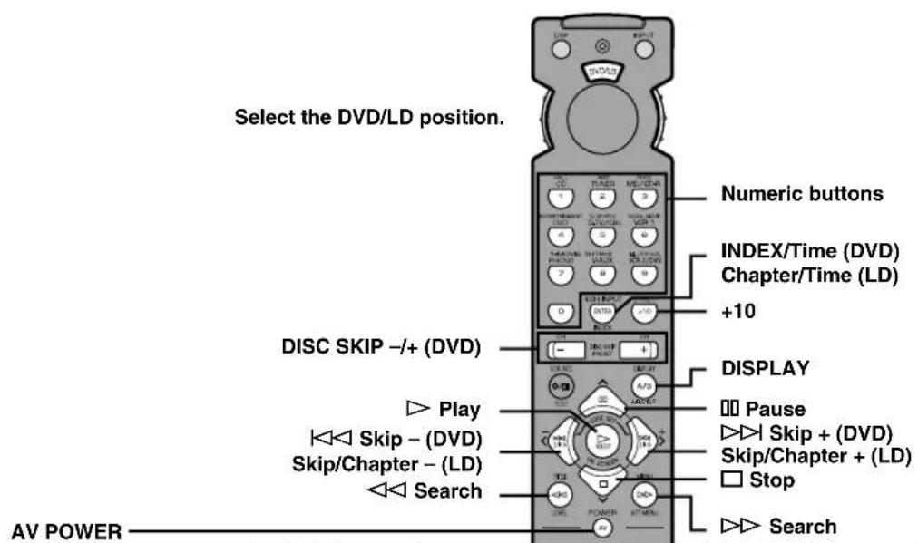
(DVD) This button turns on the DVD player that has a remote control with a power button if you have set up the code for another manufacturer.
(LD) This button turns on the LD player that has a remote control with a power button if you have set up the code for another manufacturer.
■DVD MENU position
Note
- DVD MENU operations cannot be performed for some DVD players.
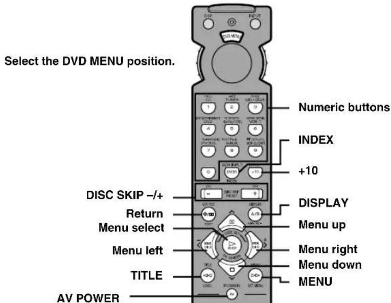
This button turns on the DVD player that has a remote control with a power button if you have set up the code for another manufacturer.
- The dark-shaded buttons do not function even if you have set up the manufacturer code.
- Some of them may not function depending on the component you have. In this case, use the original remote control supplied with your component.
■VCR position
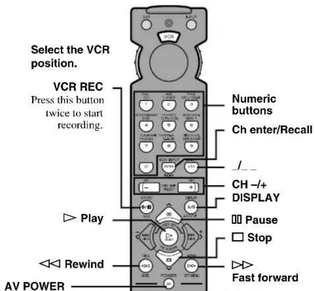
This button turns on a VCR that has a remote control with a power button if you have set up the code for your VCR.
■CBL/SAT position
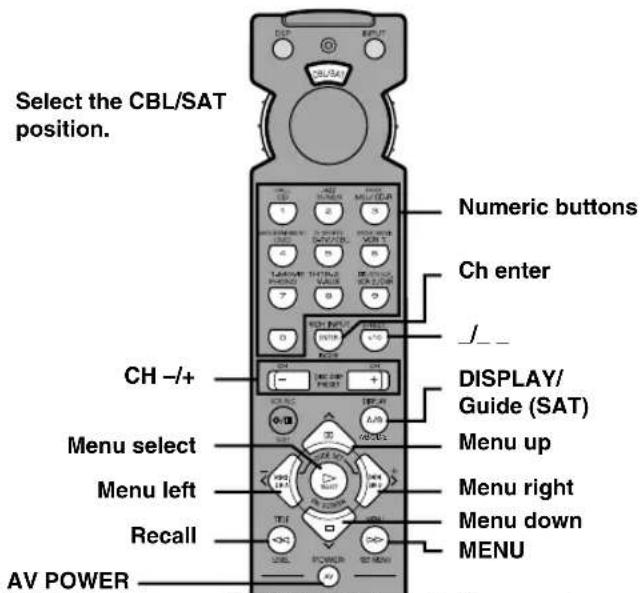
This button turns on a cable TV/satellite tuner that has a remote control with a power button if you have set up the code for your cable TV/satellite tuner.
■TV position
Note
- You can control your VCR if you have set up the code for it in the VCR position.
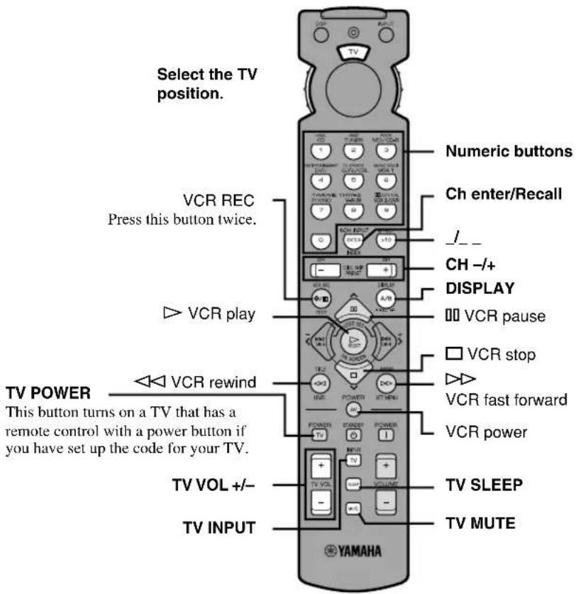
- The dark-shaded buttons do not function even if you have set up the manufacturer code.
- Some of them may not function depending on the component you have. In this case, use the original remote control supplied with your component.
Setting the Manufacturer Code
You can set up the code for the manufacturer of your component in each position of the selector dial.
1 Turn on your component to be used.
2 Set the selector dial to the desired position for the component (TAPE/MD, CD, DVD/LD, etc.).
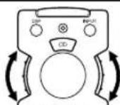
3 Press < / > at the same time for about 4 seconds.
The indicator flashes twice.
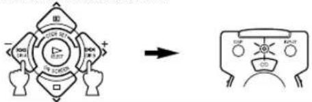
4 Use the numeric buttons to enter the four-digit manufacturer code for the component to be used. Make sure that the indicator flashes twice.
If the indicator does not flash or flashes rapidly several times, repeat step 3 and re-enter the code.
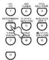
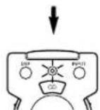
5 Press AV POWER (or any other button) to check if you have set up the code correctly.
If your component cannot be controlled with the remote control, try setting another code for the same manufacturer.

Notes
- You can set up only one code for one position.
• In the DVD/LD and DVD MENU positions:
Be sure to set the selector dial to the DVD/LD position before entering the code for the DVD/LD player. You cannot set up the code for a DVD player when the selector dial is set to the DVD MENU position. The code set up in the DVD/LD position is also simultaneously set up in the DVD MENU position. - If your component does not respond to any of the codes listed for the manufacturer, use the original remote control supplied with your component.
■To use a second (and third) VCR
You can control a second (and third) VCR in the CBL/SAT and DVD MENU positions if a cable TV/satellite tuner or DVD player is not being used.
Note
- In order to set a second (and third) VCR in the DVD MENU position, it is necessary to first set up the code for an LD player in the DVD/LD position.
1 Turn on the VCR to be used.
2 Set the selector dial to the CBL/SAT or DVD MENU position.
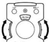
3 Press / at the same time for about 4 seconds.
The indicator flashes twice.
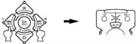
flowchart
graph TD
    A["Four-part circular structure with directional arrows"] --> B["→"]
    B --> C["Robot-like figure with 'CUP' and 'RAT' labels"]
4 Use the numeric buttons to enter the four-digit code for the second (and third) VCR. Make sure that the indicator flashes twice.
If the indicator does not flash or flashes rapidly several times, repeat step 3 and re-enter the code.
flowchart
graph TD
    A["Hall CD"] --> B["1"]
    C["MOD/CDR"] --> D["2"]
    E["JKS/MOS/CDR"] --> F["3"]
    G["EXTRUMENT DVD"] --> H["4"]
    I["1.00 MHz / 100V"] --> J["5"]
    K["1.00 MHz / 100V"] --> L["6"]
    M["7"] --> N["8"]
    O["0"] --> P["9"]
    Q["1.00 MHz / 100V"] --> R["10"]
    S["1.00 MHz / 100V"] --> T["11"]
    U["1.00 MHz / 100V"] --> V["12"]
    W["1.00 MHz / 100V"] --> X["13"]
    Y["1.00 MHz / 100V"] --> Z["14"]
5 Press AV POWER (or any other button) to check if you have set up the code correctly.
If the VCR cannot be controlled with the remote control, try setting another code for the same manufacturer.

Returning to the Factory Setting
■To return to the factory-set codes in all positions
1 Press < / > at the same time for about 4 seconds.
The indicator flashes twice.
flowchart
graph LR
    A["Central Node"] --> B["Output Node"]
    style A fill:#f9f,stroke:#333
    style B fill:#bbf,stroke:#333
2 Enter the code number "9990".
Make sure that the indicator flashes twice.
■To return to the factory-set codes in each position
1 Set the selector dial to the position for the component to be returned to the factory setting.
2 Press / at the same time for about 4 seconds.
The indicator flashes twice.
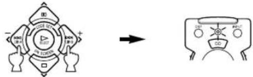
3 Enter the code number "0000".
Make sure that the indicator flashes twice.
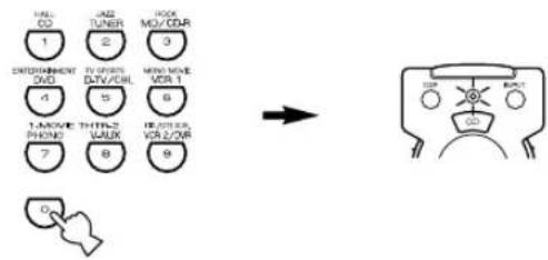
The following codes are factory set.
| Selector dial position | Component Code Set component Set code | |||
| TV TV 0101 | ||||
| CBL/SAT Satellite tuner 0006 | ||||
| VCR VCR 0002 | ||||
| DVD/LD DVD player | 0008 (YAMAHA DVD player) | |||
| CD | CD player | 0005 (YAMAHA CD player) | ||
| TAPE/MD | MD recorder | 0024 (YAMAHA MD recorder) | ||
We recommend that you write all the code numbers you have set on the table above.
SOUND FIELD PROGRAM
A digital sound field processor (DSP) based on the latest YAMAHA technology is built into this unit. It is possible to play back various sound fields for the source you are listening to.
Note
- Regardless of the program name and characteristics listed in the table below, select the sound field program that sounds best to you.
Hi-Fi DSP Programs
■For audio sources: Nos. 1 to 4
| No. | Program (group) Sub-program Features | ||
| 1 | CONCERT HALL — | A large round concert hall with a rich surround effect. Pronounced reflections from all directions emphasize the extension of sounds. The sound field has a great deal of presence, and your virtual seat is near the center, close to the stage. | |
| 2 | JAZZ CLUB | — | This is the sound field at stage front in “The Bottom Line”, a famous New York jazz club. The floor can seat 300 people to the left and right in a sound field offering a real and vibrant sound. |
| 3 | ROCK CONCERT — | The ideal program for lively, dynamic rock music. The data for this program was recorded at LA’s “hottest” rock club. The listener’s virtual seat is at the center-left of the hall. | |
| 4 | ENTERTAINMENT DISCO | This program recreates the acoustic environment of a lively disco in the heart of a big city. The sound is dense and highly concentrated. It is also characterized by a high-energy, “immediate” sound. | |
| 5CH STEREO Using this program increases the listening position range. This is a sound field suitable for background music at parties. | |||
Note
- Reverberations (sound effects) for realizing the sound field and unprocessed stereo from the left and right main speakers is output. The sound is not output from the center speaker. (The sound is output when one of these programs is selected while playing a source encoded with a Dolby Digital or DTS signal. If 5CH STEREO is selected, the sound is output from all speakers regardless of the input source.)
CINEMA DSP Programs
■For audio-video sources: Nos. 4 to 6
| No. | Program (group) Sub-program Features | ||
| 4 | ENTERTAINMENT GAME | This program adds a deep and spatial feeling to video game sounds. | |
| 5 | TV SPORTS | — | Although the presence sound field is relatively narrow, the surround sound field employs the sound environment of a large concert hall. With this program, you can enjoy watching various TV programs such as news, variety shows, music programs or sports programs. In a stereo broadcast of a sports game, the commentator is oriented at the center position, and the shouts and the atmosphere in the stadium spread on the surround side, while their spread to the rear is properly restrained. |
| 6 | MONO MOVIE | — | This program is provided for reproducing monaural video sources (such as old movies). The program produces the optimum reverberation to create sound depth by using only the presence sound field. |
■For movie programs: Nos. 7 to 9
| No. | Program (group) | Sub-program | Input source Features | ||
| 7 | MOVIE THEATER 1 | SPECTACLE | 70 mm SPECTACLE | Analog, PCM, Dolby Digital in 2-channel | This program creates the extremely wide sound field of a 70-mm movie theater. It precisely reproduces the source sound in detail, making both the video and the sound field incredibly real. This is ideal for any kind of video source encoded with Dolby Surround, Dolby Digital or DTS (especially large-scale movie productions). |
| DGTL SPECTACLE | Dolby Digital (5.1-channel) | ||||
| DTS SPECTACLE | DTS | ||||
| SCI-FI 70 mm | SCI-FI | Analog, PCM, Dolby Digital in 2-channel | This program clearly reproduces dialog and sound effects in the latest sound form of science fiction films, thus creating a broad and expansive cinematic space amid the silence. You can enjoy science fiction films in a virtual-space sound field that includes Dolby Surround, Dolby Digital and DTS-encoded software employing the most advanced techniques. | ||
| DGTL SCI-FI Dolby | Digital (5.1-channel) | ||||
| DTS SCI-FI | DTS | ||||
| 8 | MOVIE THEATER 2 | ADVENTURE | 70 mm ADVENTURE | Analog, PCM, Dolby Digital in 2-channel | This program is ideal for precisely reproducing the sound design of the newest 70-mm and multichannel soundtrack films. The sound field is made to be similar to that of the newest movie theaters, so the reverberations of the sound field itself are restrained as much as possible. |
| DGTL ADVENTURE | Dolby Digital (5.1-channel) | ||||
| DTS ADVENTURE | DTS | ||||
| GENERAL 70 | mm GENERAL Analog, PCM, Dolby Digital in 2-channel | This program is for reproducing sounds from 70-mm and multichannel soundtrack films, and is characterized by a soft and extensive sound field. The presence sound field is relatively narrow. It spatially spreads all around and toward the screen, restraining the echo effect of conversations without losing clarity. For the surround sound field, the harmony of music or chorus sounds beautifully in a wide space at the rear of the sound field. | |||
| DGTL GENERAL | Dolby Digital (5.1-channel) | ||||
| DTS GENERAL | DTS | ||||
| 9 | DD/DTS SURROUND | NORMAL PRO | LOGIC/NORMAL | Analog, PCM, Dolby Digital in 2-channel | The built-in decoder precisely reproduces sounds and sound effects from sources. The highly efficient decoding process improves crosstalk and channel separation, and makes sound positioning smoother and more precise. In this program, the digital sound field processor is not turned on. |
| DOLBY DIGITAL/NORMAL | Dolby Digital (5.1-channel) | ||||
| DTS DIGITAL SUR./NORMAL | DTS | ||||
| ENHANCED PRO | LOGIC/ENHANCED | Analog, PCM, Dolby Digital in 2-channel | This program ideally simulates the multi-surround speaker systems of the 35-mm film theaters. Dolby Pro Logic decoding, Dolby Digital decoding or DTS decoding and digital sound field processing create precise effects without altering the original sound orientation. The surround effects produced by this sound field wrap around the viewer naturally from the back to the left and right, and toward the screen. | ||
| DOLBY DIGITAL/ENHANCED | Dolby Digital (5.1-channel) | ||||
| DTS DIGITAL SUR./ENHANCED | DTS | ||||
Notes
- The “DSP” indicator does not light up when selecting the sub-program “NORMAL” of the ☐/DTS SURROUND program.
- If "1A CENTER SP" on the SET MENU is set to NONE, no sound is output from the center speaker.
- The effect sound is output from the main speakers when a monaural source is played with CINEMA DSP program groups 4 (GAME) and 5 to 8.
■MOVIE THEATER 1 and 2
Most commercially available movie software has 4-channel (left, center, right and surround) sound information encoded by Dolby Surround matrix processing and stored on the left and right tracks. These signals are processed by the Dolby Pro Logic decoder. The MOVIE THEATER programs are designed to recreate the spaciousness and delicate nuances of sound that tend to be lost in the encoding and decoding processes.
The 6-channel soundtracks found on 70-mm film produce precise sound field localization and rich, deep sound without using matrix processing. This unit's MOVIE THEATER 70 mm programs provide the same quality of sound and sound localization that 6-channel soundtracks do.
When the input source is analog, PCM or encoded with Dolby Digital in 2-channel
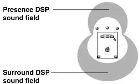
These programs express an immense sound field and a large surround effect. They also give depth to the sound from the main speakers to recreate the realistic sound of a Dolby Stereo theater.
70 mm SPECTACLE
70 mm SCI-FI
70 mm ADVENTURE
70 mm GENERAL
The built-in Dolby Digital or DTS decoder brings the professional-quality sound designed for movie theaters into your home. With the unit's MOVIE THEATER programs, you can recreate a dynamic sound that gives you the feeling of being at a public theater in your listening room by using Dolby Digital or DTS technology.
When the input source is encoded with Dolby Digital (5.1-channel) or DTS (Tri-Field CINEMA DSP)
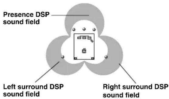
These programs use YAMAHA's tri-field DSP processing on each of the Dolby Digital or DTS signals for the front, left surround and right surround channels. This processing enables this unit to reproduce the immense sound field and surround expression of a Dolby Digital- or DTS-equipped movie theater without sacrificing the clear separation of all channels.
DGTL SPECTACLE
DTS SPECTACLE
DGTL SCI-FI
DTS SCI-FI
DGTL ADVENTURE
DTS ADVENTURE
DGTL GENERAL
DTS GENERAL

- If a Dolby Digital signal or DTS signal is input when the input mode is set to AUTO, the DSP program will be automatically switched to the Dolby Digital playback sound field or DTS playback sound field.
SOUND FIELD PROGRAM PARAMETER EDITING
What is a sound field?
What really creates the rich, full tones of a live instrument are the multiple reflections from the walls of the room. In addition to making the sound “live”, these reflections enable us to tell where the player is situated, and the size and shape of the room in which we are sitting.
■Elements of a sound field
In any environment, in addition to the direct sound coming straight to our ears from the player's instrument, there are two distinct types of sound reflections that combine to make up the sound field:
Early reflections
Reflected sounds reach our ears extremely rapidly (50 ms – 100 ms after the direct sound), after reflecting from one surface only — for example, from the ceiling or a wall. These reflections fall into specific patterns for any particular environment, and provide vital information to our ears. Early reflections actually add clarity to the direct sound.
Reverberations
These are caused by reflections from more than one surface — walls, ceiling, the back of the room — so numerous that they merge together to form a continuous sonic “afterglow”. They are non-directional, and lessen the clarity of the direct sound.
Direct sound, early reflections and subsequent reverberation taken together help us to determine the subjective size and shape of the room, and it is this information that the digital sound field processor reproduces in order to create sound fields.
If you could create the appropriate early reflections and subsequent reverberations in your listening room, you would be able to create your own listening environment. The acoustics in your room could be changed to those of a concert hall, a dance floor, or virtually any size room at all. This ability to create sound fields at will is exactly what YAMAHA has done with the digital sound field processor.
Sound Field Program Parameters
DSP programs consist of some parameters to determine the apparent room size, reverberation time, distance from you to the performer, etc. In each program, these parameters are set with values precisely calculated by YAMAHA to create a sound field unique to the program. It is recommended to use DSP programs without changing the values of parameters; however, this unit also allows you to create your own sound fields. Starting with one of the built-in programs, you can adjust those parameters.
Each DSP program has a set of parameters that allow you to change the characteristics of the acoustic environment to precisely create the effect you want. These parameters correspond to the many natural acoustic factors that create the sound field you experience in an actual concert hall or other listening environment. The size of the room, for example, affects the length of time between the early reflections. The “ROOM SIZE” parameter provided in many of the DSP programs alters the timing between these reflections, thus changing the shape of the “room” you are listening. In addition to room size, the shape of the room and the characteristics of its surfaces have a significant effect on the final sound. Surfaces that absorb sound, for example, cause the reflections and reverberations to die out more quickly, while highly reflective surfaces allow the reflections to carry on for a longer period of time. The digital sound field parameters allow you to control these and many other factors that contribute to your personal sound field, allowing you to essentially “redesign” the concert halls, theaters, etc. provided to create custom-tailored listening environments that ideally match your mood and music.
See "Sound Field Parameter Descriptions".
Changing Parameter Settings
Although it is possible to enjoy playback on your system without changing default setting parameters for the sound field program, it is also possible to enjoy specifically tailor the sound field program to the characteristics of the source and the acoustics of the listening room.
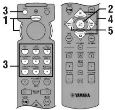
1 Set the selector dial to the DSP/TUN (or AMP/TUN) position.

or

2 Turn on the video monitor and press ON SCREEN repeatedly to select the full display mode.
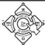
3 Select a DSP program you want to adjust.
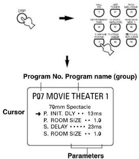
flowchart
graph TD
    A["Program No. Program name (group)"] --> B["Cursor"]
    B --> C["P07 MOVIE THEATER 1"]
    C --> D["70mm Spectacle"]
    D --> E["P. INIT. DLY •• 13ms"]
    D --> F["P. ROOM SIZE •• 1.0"]
    D --> G["S. DELAY •••• 23ms"]
    D --> H["S. ROOM SIZE •• 1.0"]
    C --> I["Parameters"]
Example of the MOVIE THEATER 1
4 Press ∨∨∨ to select the parameter.
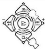
5 Press < / > to change the parameter value.
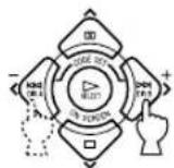

- When you set the parameter to a value other than the factory-set value, an asterisk mark (*) appears by the parameter name on the video monitor.
6 Repeat steps 3 to 5 above as necessary to change other program parameters.
Memory back-up
The memory back-up circuit prevents the stored data from being lost even if this unit is set in the standby mode, the power cord is disconnected from the AC outlet, or the power supply is temporarily cut due to power failure. However, if the power is cut for more than one week, the parameter value you edited will return to the factory setting. If so, edit the parameter value again.
Resetting a Parameter to the Factory-set Value
Select the parameter you want to reset. Then press and hold < or > until the value temporarily stops at the factory-set value. The asterisk mark (*) by the parameter name disappears on the video monitor.
Notes
- The available parameters may be displayed on more than one OSD page for some of the programs. To scroll through pages, press ∧/∨.
- You cannot change parameter values when "10 MEMORY GUARD" on the SET MENU is set to ON. If you want to change the parameter values, set "10 MEMORY GUARD" to OFF.
Sound Field Parameter Descriptions
You can adjust the values of certain sound field parameters so the sound fields are recreated accurately in your listening room.
Note
- Not all of the following parameters can be found in every program.
■INIT.DLY (initial delay)
(P.INIT.DLY — for the presence sound field)
Function: This parameter changes the apparent distance from the sound source by adjusting the delay between the direct sound and the first reflection heard by the listener.
Control range: 1 - 99 msec
Description: The smaller the value, the closer the sound source seems to the listener. The larger the value, the farther the apparent distance seems. For a small room, this parameter would be set to a small value, for a large room, set it to a large value.
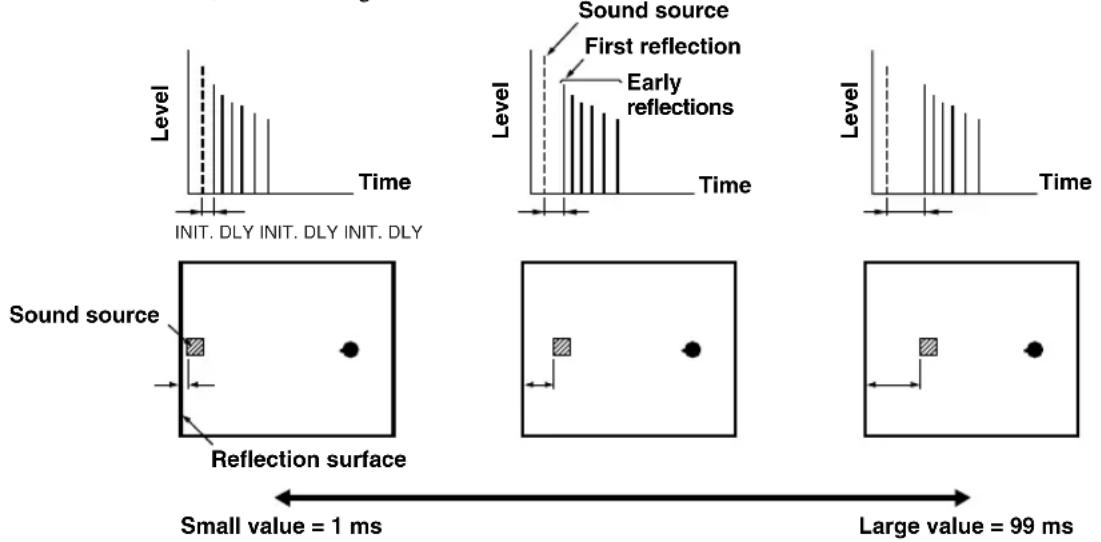
■ROOM SIZE
(P.ROOM SIZE — for the presence sound field)
Function: This parameter adjusts the apparent size of the surround sound field. The larger the value, the larger the surround sound field becomes.
Control range: 0.1 - 2.0
Description: As the sound is repeatedly reflected around a room, the larger the hall is, the longer the time between the original reflected sound and the subsequent reflections. By controlling the time between the reflected sounds, you can change the apparent size of the virtual venue. Changing this parameter from one to two, doubles the apparent length of the room.
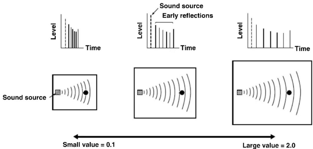
LIVENESS
Function: This parameter adjusts the reflectivity of the virtual walls in the hall by changing the rate at which the early reflections decay.
Control range: 0 - 10
Description: The early reflections of a sound source decay much faster in a room with acoustically absorbent wall surfaces than in one which has highly reflective surfaces. A room with acoustically absorbent surfaces is referred to as “dead,” while a room with highly reflective surfaces is referred to as “live”. The “LIVENESS” parameter lets you adjust the early reflection decay rate, and thus the “liveness” of the room.
■S.DELAY (surround delay)
Function: This parameter adjusts the delay between the direct sound and the first reflection in the surround sound field.
Control range: 0 - 49 msec (The range depends on the signal format.)
■S.INIT.DLY (surround initial delay)
Function: This parameter adjusts the delay between the direct sound and the first reflection on the surround side of the sound field. You can only adjust this parameter when at least two front channels and two rear channels are used.
Control range: 1 - 49 msec
■S.ROOM SIZE (surround room size)
Function: This parameter adjusts the apparent size of the surround sound field.
Control range: 0.1 - 2.0
■S.LIVENESS (surround liveness)
Function: This parameter adjusts the apparent reflectivity of the virtual walls in the surround sound field.
Control range: 0 - 10
■CT.DELAY (center delay)
Function: These parameters adjust the sound delay for each channel in 5 channel stereo mode.
Control range: 0 - 50 msec
■LS.DELAY (left surround delay)
Function: These parameters adjust the sound delay for each channel in 5 channel stereo mode.
Control range: 0 - 50 msec
■RS.DELAY (right surround delay)
Function: These parameters adjust the sound delay for each channel in 5 channel stereo mode.
Control range: 0 – 50 msec
TROUBLESHOOTING
Refer to the chart below when the unit does not function properly. If the problem you are experiencing is not listed below or if the instruction below does not help, set this unit in the standby mode, disconnect the power cord and contact the nearest authorized YAMAHA dealer or service center.
General
| Problem Cause | Remedy | Refer to page | |
| The unit fails to turn on when STANDBY/ON (or POWER) is pressed, or enters in the standby mode soon after the power has been turned on. | The power cord is not connected or the plug is not completely inserted. | Firmly connect the power cord. | 19 |
| The IMPEDANCE SELECTOR switch on the rear panel is not fully set to the left or right position. | Set the switch fully to the left or right position when the unit is in the standby mode. | 19 | |
| The protection circuitry has been activated. | Make sure all speaker wire connections on this unit and on all speakers are secure and that the wire for each connection does not touch anything other than its respective connection. | 16, 17 | |
| On-screen display does not appear. | The setting for the on-screen display is set to “DISPLAY OFF”. | Select the full display or short display mode. | 20 |
| The BLUE BACK setting under “9 DISPLAY SET” on the SET MENU is set to OFF, and no video signal is input to this unit. | Set BLUE BACK to AUTO to always show the OSD. | 37 | |
| No sound and/or no picture. | Incorrect input or output cable connections. | Connect the cables properly. If the problem persists, the cables may be defective. | 12 – 15 |
| An appropriate input source has not been selected. | Select an appropriate input source with INPUT ◀/▷ or 6CH INPUT (or the input selector buttons). | 24 | |
| The speaker connections are not secure. | Secure the connections. | 16, 17 | |
| The main speakers to be used have not been selected properly. | Select the main speakers with SPEAKERS A and/or B. | 24 | |
| The volume is turned down. | Turn up the volume. | 25 | |
| The sound is muted. | Press MUTE or any operation buttons to cancel a mute and adjust the volume. | 25 | |
| Digital signals other than PCM audio, Dolby Digital or DTS signal which this unit cannot reproduce are being input to this unit by playing a CD-ROM, etc. | Play a source whose signals this unit can reproduce. | — | |
| The picture does not appear. | The output and input for the video are connected to different types of video jacks. | Make connections using the same type of jack (between composites, S-VIDEOs, or components) for both the input and output. | 14, 15 |
| The sound suddenly goes off. | The protection circuit has been activated because of a short circuit, etc. | Check the IMPEDANCE SELECTOR switch is set to the appropriate position and then turn the unit back on. | 19 |
| Check the speaker wires are not touching each other and then turn the unit back on. | 16, 17 | ||
| The sleep timer has functioned. | Turn on the power, and play the source again. | 39 | |
| The sound is muted. | Press MUTE or any operation buttons to cancel a mute and adjust the volume. | 25 | |
| Only the speaker on one side can be heard. | Incorrect cable connections. Connect the cables | properly. If the problem persists, the cables may be defective. | 12 – 17 |
TROUBLESHOOTING
| Problem Cause | Remedy | Refer to page | |
| No sound from the effect speakers. | The sound effect is off. | Press EFFECT to turn it on. | 29 |
| A Dolby Surround, Dolby Digital or DTS decoding DSP program is being used with material not encoded with Dolby Surround, Dolby Digital or DTS. | Select another DSP program. | 47, 48 | |
| A 96-kHz sampling digital signal is being input to this unit. | 25 | ||
| No sound from the center speaker. | The output level of the center speaker is set to minimum. | Raise the level of the center speaker. | 38 |
| “1A CENTER SP” on the SET MENU is set to NONE. | Select the appropriate mode for your center speaker. | 32 | |
| One of the Hi-Fi DSP programs (1 to 4) has been selected. | Select another DSP program. | 47, 48 | |
| The source encoded with a Dolby Digital or DTS signal does not have a center channel signal. | — | ||
| No sound from the rear speakers. | The output level of the rear speakers is set to minimum. | Raise the output level of the rear speakers. | 38 |
| A monaural source is being played with the program 9. | Select another DSP program. | 47, 48 | |
| No sound from the subwoofer. | “1D LFE/BASS OUT” on the SET MENU is set to MAIN when a Dolby Digital or DTS signal is being played. | Select SWFR or BOTH. | 34 |
| “1D LFE/BASS OUT” on the SET MENU is set to SWFR or MAIN when a 2-channel source is being played. | Select BOTH. | 34 | |
| The source does not contain low bass signals (90 Hz and below). | — | ||
| Poor bass reproduction. | “1D LFE/BASS OUT” on the SET MENU is set to SWFR or BOTH and your system does not include a subwoofer. | Select MAIN. | 34 |
| The output mode for each speaker (main, center or rear) on the SET MENU does not match your speaker configuration. | Select the appropriate output mode for each speaker based on the size of the speakers in your configuration. | 32, 33 | |
| A “humming” sound can be heard. | Incorrect cable connections. | Firmly connect the audio plugs. If the problem persists, the cables may be defective. | 12 – 15 |
| No connection from the turntable to the GND terminal. | Connect the grounding cord of your turntable to the GND terminal of this unit. | 12, 13 | |
| The volume level is low while playing a record. | The record is being played on a turntable with an MC cartridge. | The turntable should be connected to the unit through an MC-head amplifier. | 12 |
| The volume level cannot be increased, or the sound is distorted. | The component connected to the REC OUT jacks of this unit is turned off. | Turn on the power to the component. | 12 |
| The effect and surround sounds cannot be recorded. | It is not possible to record the effect and surround sounds by a recording component. | 30 | |
| A source cannot be recorded by a digital recording component connected to the DIGITAL OUTPUT jack of this unit. | A source component is only connected to the analog input jacks of this unit. | Connect the source component to the digital input jacks of this unit. | 12 – 15 |
| The sound field parameters and some other settings on this unit cannot be changed. | “10 MEMORY GUARD” on the SET MENU is set to ON. | Select OFF. | 37 |
| This unit does not operate properly. | The internal microcomputer has been frozen by an external electric shock (such as lightning or excessive static electricity) or by a power supply with low voltage. | Disconnect the AC power cord from the outlet and then plug it in again after about 30 seconds. | — |
| The sound is degraded when listening with headphones connected to a tape deck or CD player that is connected to this unit. | This unit is in the standby mode. Turn on the power of the unit. | — | |
| There is noise interference from digital or high-frequency equipment, or the unit. | The unit is too close to the digital or high-frequency equipment. | Move the unit further away from such equipment. | — |
■Remote control
| Problem Cause | Remedy | Refer to page | |
| The remote control does not work nor function properly. | Wrong distance or angle. | The remote control will function within a maximum range of 6 m (20 feet) and no more than 30 degrees off-axis from the front panel. | 8 |
| Direct sunlight or lighting (from an inverter type of fluorescent lamp, etc.) is striking the remote control sensor of this unit. | Reposition the unit. | — | |
| The batteries are weak. | Replace all batteries with new ones. | 3 | |
| The unit or other component cannot be controlled. | The component to be controlled has not been selected. | Set the selector dial to the appropriate position, corresponding to the component to be controlled. | 40 |
| The remote control cannot control system components. | — | ||
| The manufacturer code has not been set up properly. | Enter the code again. | 45 | |
| Try setting another code for the same manufacturer. | |||
| Depending on the manufacturer or the model, some components cannot be controlled with this unit's remote control even though the code has been set up properly. | Use the original remote control supplied with your component. | — |
After this unit has been exposed to a strong external electric shock (such as lightning and strong static electricity) or if you mishandle the operation of this unit, it may not function properly. In these cases, set this unit in the standby mode, disconnect the power cord, plug it back in after 30 seconds, and start operating.
SPECIFICATIONS
AUDIO SECTION
- Minimum RMS Output Power for Main, Center, Rear 20 Hz to 20 kHz, 0.06% THD, 8 ohms .... 90 W 1 kHz, 0.06% THD, 8 ohms .... 100 W
• DIN Standard Output Power [Europe model only] 1 kHz, 0.7% THD, 4 ohms .... 130 W
- IEC Output Power [Europe model only] 1 kHz, 0.06% THD, 8 ohms .... 100 W
• Maximum Power (EIAJ) [China and General models only] 1 kHz, 10% THD, 8 ohms .... 115 W
• Dynamic Power (IHF) 8/6/4/2 ohms 120/140/175/210 W
- Damping Factor 20 Hz to 20 kHz, 8 ohms .... 80 or more
- Frequency Response CD to Main L/R 10 Hz to 100 kHz, -3 dB
- RIAA Equalization Deviation PHONO (MM) .... ±0.5 dB
- Total Harmonic Distortion PHONO MM (20 Hz to 20 kHz, 1 V, REC OUT) .... 0.02% or less CD, etc. (20 Hz to 20 kHz, 45 W, 8 ohms, Main L/R) .... 0.06% or less
- Signal to Noise Ratio (THF-A Network) PHONO MM to REC OUT (5 mV, shorted) [Europe and U.K. models] .... 81 dB or more [China and General models] .... 86 dB or more CD (250 mV, shorted) to Main L/R, Effect Off .... 100 dB or more
- Residual Noise (IHF-A Network) Main L/R 150 μV or less
- Channel Separation (1 kHz/10 kHz) CD (5.1 kohms terminated) to Main L/R 60 dB/45 dB
- Tone Control (Main L/R) BASS Boost/Cut ....±10 dB/50 Hz TREBLE Boost/Cut ....±10 dB/20 kHz BASS EXTENSION ....+6 dB/60 Hz
- Phones Output .... 400 mV/560 ohms
- Input Sensitivity CD, etc .... 150 mV/47 kohms PHONO .... 2.5 mV/47 kohms 6CH INPUT .... 150 mV/47 kohms
• Maximum Input Signal PHONO MM (1 kHz, 0.1% THD) .... 100 mV or more CD, etc. (1 kHz, 0.5% THD) .... 2.2 V or more
- Output Level REC OUT .... 150 mV/1.2 kohms PRE OUT [Europe and U.K. models only] .... 2.1 V/1.2 kohms SUBWOOFER .... 4.0 V/1.2 kohms
VIDEO SECTION
- Video Signal Type [Europe and U.K. models] .... PAL [China and General models] .... NTSC
- Composite Video Signal Level 1 Vp-p/75 ohms
• S-Video Signal Level Y .... 1 Vp-p/75 ohms C .... 0.286 Vp-p/75 ohms
- Component Video Signal Level Y .... 1 Vp-p/75 ohms P_B/C_B, P_R/C_R .... 0.7 Vp-p/75 ohms
- Signal to Noise Ratio 50 dB or more
- Frequency Response (MONITOR OUT) Composite, S-Video .... 5 Hz to 10 MHz, -3 dB Component .... DC to 30 MHz, -3 dB
GENERAL
• Power Supply [Europe and U.K. models] .... AC 230 V/50 Hz [China model] .... AC 220 V/50 Hz [General model] .... AC110/120/220/240 V, 50/60 Hz
• Power Consumption .... 260 W Standby Mode [Europe and U.K. models] .... 0.9 W
• Maximum Power Consumption [General model only] 5-ch, 10% THD ....610 W
- AC Outlets (Total 100 W maximum) [Europe, China and General models] .... 2 (SWITCHED) [U.K. model] .... 1 (SWITCHED)
- Dimension (W x H x D) 435 x 151 x 390 mm
- Weight 10.5 kg
- Accessories ...... Remote Control ...... Batteries ...... Quick Reference Card ...... Connection Guide
* Specifications are subject to change without notice.
GLOSSARY
■Dolby Surround
Dolby Surround uses a four analog channel recording system to reproduce realistic and dynamic sound effects: two left and right main channels (stereo), a center channel for dialog (monaural), and a rear channel for special sound effects (monaural). The rear channel reproduces sound within a narrow frequency range.
Dolby Surround is widely used with nearly all video tapes and laser discs, and in many TV and cable broadcasts as well. The Dolby Pro Logic decoder built into this unit employs a digital signal processing system that automatically stabilizes the volume on each channel to enhance moving sound effects and directionality.
■Dolby Digital
Dolby Digital is a digital surround sound system that gives you completely independent multi-channel audio. With three front channels (left, center and right), and two rear stereo channels, Dolby Digital provides five full-range audio channels. With an additional channel especially for bass effects, called LFE (low frequency effect), the system has a total of 5.1 channels (LFE is counted as 0.1 channel).
Using two-channel stereo for the rear speakers, more accurate moving sound effects and surround sound environment are possible than with Dolby Surround. The wide dynamic range (from maximum to minimum volume) reproduced by the five full-range channels and the precise sound orientation generated using digital sound processing provide listeners with previously unheard of excitement and realism.
With this unit, any sound environment from monaural up to a 5.1-channel configuration can be freely selected for your enjoyment.
■DTS (Digital Theater Systems) Digital Surround
DTS digital surround was developed to replace the analog soundtracks of movies with a six-channel digital sound track, and is now rapidly gaining popularity in movie theaters around the world. Digital Theater Systems Inc. has developed a home theater system so that you can enjoy the depth of sound and natural spatial representation of DTS digital surround in your home.
This system is practically distortion-free, clear 6-channel sound (technically, a left, right and center channels, two rear channels, plus an LFE 0.1 channel as a subwoofer, for a total of 5.1 channels).
■LFE 0.1 channel
This channel is for the reproduction of low bass signals. The frequency range for this channel is 20 Hz to 120 Hz. This channel is counted as 0.1 because it only enforces a low frequency range compared to the full-range reproduced by the other 5 channels in a Dolby Digital or DTS 5.1 channel systems.
CINEMA DSP

Since the Dolby Surround and DTS systems were originally designed for use in movie theaters, their effect is best felt in a theater having many speakers and designed for acoustic effects. Since home conditions, such as room size, wall material, number of speakers, and so on, can differ so widely, it's inevitable that there are differences in the sound heard as well. Based on a wealth of actually measured data, YAMAHA CINEMA DSP uses YAMAHA original sound field technology to combine Dolby Pro Logic, Dolby Digital and DTS systems to provide the visual and audio experience of movie theater in the listening room of your own home.
■SILENT CINEMA
YAMAHA has developed a natural, realistic sound effect DSP algorithm for headphones.
Parameters for headphones have been set for each sound field so that accurate representations of all the sound field programs can be enjoyed on headphones.
■Virtual CINEMA DSP
YAMAHA has developed a virtual CINEMA DSP algorithm that allows you to enjoy DSP sound field surround effects even without any rear speakers by using virtual rear speakers.
It is even possible to enjoy virtual CINEMA DSP in a minimum two-speaker system that does not include a center speaker.
■S VIDEO signal
With S VIDEO signal system, the video signal normally transmitted using a pin cable is separated and transmitted as the Y signal for the luminance and the C signal for the chrominance through the S VIDEO cable. Using the S VIDEO jack eliminates video signal transmission loss and allows recording and playback of even more beautiful images.
■Component video signal
With the component video signal system, the video signal is separated into the Y signal for the luminance and the P_R/C_B and P_R/C_R signals for the chrominance. Color can be reproduced more faithfully with this system because each of these signals is independent. The component signal is also called the “color difference signal” because the luminance signal is subtracted from the color signal. A monitor with component input jacks is required in order to use the component signal for output.
■PCM (Linear PCM)
Linear PCM is a signal format under which an analog audio signal is digitized, recorded and transmitted without using any compression. This is used as a method of recording CDs and DVD audio. The PCM system uses a technique for sampling the size of the analog signal per very small unit of time. Standing for “pulse code modulation”, the analog signal is encoded as pulses and then modulated for recording.
■Sampling frequency and number of quantized bits
When digitizing an analog audio signal, the number of times the signal is sampled per second is called the sampling frequency, while the degree of fineness when converting the sound level into a numeric value is called the number of quantized bits.
The range of rates that can be played back is determined based on the sampling rate, while the dynamic range representing the sound level difference is determined by the number of quantized bits. In principle, the higher the sampling frequency, the wider the range of frequencies that can be played back, and the higher the number of quantized bits, the more finely the sound level can be reproduced.
■I/O assignment (SET MENU)
Although component is normally connected according to jack names shown on the rear panel, this unit includes a function that assigns jacks according to the component being connected. If the component being used differs from the component name shown for this unit's component video input jacks or digital input/output jacks, it is possible to assign jacks according to the component being connected. This makes it possible to change the jack assignment and effectively connect more component.
INDEX
A
Accesories 3
AC outlets 19
B
Balance (L/R BALANCE) (SET MENU) 34
BGV function 26
C
CBL/SAT position 44
CD position 42
CINEMA DSP 47,60
Component video 61
Connections
Audio components (MD recorder, CD recorder,
CD player and turntable) 12
External amplifier (Europe and U.K. models only) ..... 18
External decoder 18
Power supply cords 19
Speakers 16
Video components (DVD player, VCR and
TV/digital TV or cable TV/satellite tuner) 14
D
Delay time 37
DISPLAY SET (SET MENU)
BLUE BACK 37
DIMMER 37
OSD SHIFT 37
DOLBY D. SET (SET MENU)
D-RANGE 36
LFE LEVEL 36
Dolby Digital 60
Dolby Surround (Dolby Pro Logic) 60
DSP program
CINEMA DSP program 47
Hi-Fi DSP program 47
DTS 60
DTS SET (SET MENU) 36
Dust protection cap 12
DVD/LD position 43
DVD MENU position 43
E
External decoder 18
F
Front panel 4
Front panel display 9
H
HP TONE CTRL (SET MENU) 35
|
I/O ASSIGNMENT (SET MENU) 35,61
IMPEDANCE SELECTOR switch 19
INPUT MODE (SET MENU) 35
Input modes 26
L
LFE 36,60
M
Manufacturer codes 45, i
Memory back-up 32, 38, 51
MEMORY GUARD (SET MENU) 37
Muting 25
P
PCM 61
PHONO jack 12
Playing 24
Power supply cords 19
R
Rear panel 10
Recording 30
Remote control
Basic operation 6
Batteries 3
Operation range 8
Setup codes 45
S
Sampling frequency 25,61
Selector dial 6,40
SET MENU 31
SILENT CINEMA 29,60
Sleep timer 39
Sound field 50
SP DELAY TIME (SET MENU) 37
Speaker
Output balance (test tone) 22
Output levels (LEVEL mode) 38
Output mode (SET MENU) 21
Placement 11
SPEAKER SET (SET MENU)
CENTER SP 32
LFE/BASS OUT 34
MAIN LEVEL 34
MAIN SP 33
REAR L/R SP 33
Stereo reproduction 29
Subwoofer 17
S VIDEO 61
T
TAPE/MD position 42
Test tone (TEST DOLBY SUR.) 22
TV position 44
V
VCR position 44
Video jack 14
Virtual CINEMA DSP 29,60
ATTENTION : TENIR COMPTE DES PRÉCAUTIONS CI-DESSOUS AVANT DE FAIRE FONCTIONNER L'APPAREIL.
natural_image
Illustration of four cylindrical batteries with battery terminals (no text or symbols)Guide des raccordements (Connection guide)
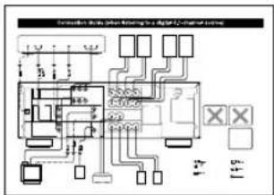
flowchart
graph TD
    A["Switch"] --> B["Relays"]
    B --> C["Meters"]
    C --> D[" meters"]
    D --> E[" meters"]
    E --> F[" meters"]
    F --> G[" meters"]
    G --> H[" meters"]
    H --> I[" meters"]
    I --> J[" meters"]
    J --> K[" meters"]
    K --> L[" meters"]
    L --> M[" meters"]
    M --> N[" meters"]
    N --> O[" meters"]
    O --> P[" meters"]
    P --> Q[" meters"]
    Q --> R[" meters"]
    R --> S[" meters"]
    S --> T[" meters"]
    T --> U[" meters"]
    U --> V[" meters"]
    V --> W[" meters"]
    W --> X[" meters"]
    X --> Y[" meters"]
⑦BASS EXTENSION ON/OFF
① Prises DIGITAL OUTPUT
② Prises DIGITAL INPUT
③ Borne GND
→ INIT. DLY....45ms ROOM SIZE 1.0. LIVENESS.....5
P01 CONCERT HALL
Remarques
7 DTS SET
8 SP DELAY TIME
9 DISPLAY SET
BLUE BACK
OSD SHIFT
DIMMER
10 MEMORY GUARD
→[A] ····· VCR 1 [B] ····· D-TV/CBL

SML (petite)
NONE (aucune)
SMALL (petites)
Remarque
SML (petites)
Options : SWFR (subwoofer), MAIN (principales), BOTH (les deux)
MAIN (principales)
Remarques
(3) DVD
(4) D-TV/CBL
4C OPTICAL IN
flowchart
graph LR
    A["Hand icon"] --> B["Arrow"]
    B --> C["Diagram with circles, arrows, and labels: MODE, SIGHT, RUT"]
    C --> D["Hand icon with arrows, labels: MODE, SIGHT, RUT"]
8/6/4/2 ohms 120/140/175/210 W
BASS : Accentuation/désaccentuation ....±10 dB/50 Hz TREBLE : Accentuation/désaccentuation ....±10 dB/20 kHz BASS EXTENSION ....+6 dB/60 Hz
DISPLAY SET (SET MENU)
BLUE BACK 37
DIMMER 37
OSD SHIFT 37
DOLBY D. SET (SET MENU)
D-RANGE 36
LFE LEVEL 36
Dolby Digital 60
Dolby Surround (Dolby Prologic) 60
DTS 60
DTS SET (SET MENU) 36
E
Enceinte
I/O ASSIGNMENT (SET MENU) 35,61
INPUT MODE (SET MENU) 35
L
Lecture 24
LFE 36,60
M
MEMORY GUARD (SET MENU) 37
SPEAKER SET (SET MENU)
CENTER SP 32
LFE/BASS OUT 34
MAIN LEVEL 34
MAIN SP 33
REAR L/R SP....33
Subwoofer.... 17
T
Télécommande
7 DTS SET (DTS LFE-Pegel) 36
Confidential Unpublished Works. ©1992-1997 Dolby
natural_image
Illustration of four cylindrical batteries arranged in a row (no text or symbols)⑦BASS EXTENSION ON/OFF
Hinweise
SET MENU 1/3
1 SPEAKER SET 2 L/R BALANCE 3 HP TONE CTRL →4 I/O ASSIGNMENT ▲/▼ : Up/Down -/+ : Enter

flowchart
graph LR
    A["Device with labeled components"] --> B["4B OPTICAL OUT"]
    B --> C["(1) ⋯⋯⋯ MD/CD-R"]

flowchart
graph TD
    A["Multi-layered circular component"] --> B["4A CMPNT-V INPUT"]
    B --> C["→ [A"] ••••• VCR 1\n["B"] •••••• D-TV/CBL]

SML
NONE
■1B MAIN SP
SMALL
Hinweis

Hinweise
-10 dB
→[A] ····· DVD [B] ····· D-TV/CBL
7 DTS SET (DTS LFE-Pegel)
flowchart
graph TD
    A["Hall CD"] --> B["1"]
    C["1-2/3/4/5/6/7/8/9/10/11/12/13/14/15/16/17/18/19/20/21/22"] --> D["2"]
    E["1-2/3/4/5/6/7/8/9/10/11/12/13/14/15/16/17/18/19/20/21"] --> F["3"]
    G["1-2/3/4/5/6/7/8/9/10/11/12/13/14/15/16/17"] --> H["5"]
    I["1-2/3/4/5/6/7/8/9/10/11"] --> J["6"]
    K["1-2/3/4/5/6/7/8/9/10"] --> L["7"]
    M["1-2/3/4/5/6/7/8/9/10"] --> N["8"]
    O["1-2/3/4/5/6/7/8/9"] --> P["9"]
    Q["Ground"] --> R["Output"]
■PCM (Lineare Pulscode-Modulation)
DISPLAY SET (SET MENU)
BLUE BACK 37
DIMMER 37
OSD SHIFT 37
DOLBY D. SET (SET MENU)
D-RANGE 36
LFE LEVEL 36
Dolby Digital 60
Dolby Surround (Dolby Pro Logic) 60
DSP-Programm
CINEMA DSP-Programm 47
DTS SET (SET MENU) 36
DVD/LD-Position 43
DVD MENU-Position 43
E
Eingangsmodi 26
I/O ASSIGNMENT (SET MENU) 35,61
IMPEDANCE SELECTOR-Wahlschalter 19
INPUT MODE (SET MENU) 35
L
SPEAKER SET (SET MENU)
CENTER SP 32
LFE/BASS OUT 34
MAIN LEVEL 34
MAIN SP 33
REAR L/R SP 33
JUSTERING AV HÖGTALARNAS UTNIVÄER 22
Innan du börjar 22
CINEMA DSP-program 47
REDIGERING AV LJUDFÄLTSPROGRAMMENS PARAMETRAR .... 50
natural_image
Line drawing of four cylindrical batteries with battery terminals (no text or symbols)Snabbreferenskort
(Quick Reference Card)
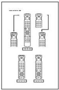
flowchart
graph TD
    A["Mobile Phone 1"] --> B["QR Code"]
    C["Mobile Phone 2"] --> D["QR Code"]
    E["Mobile Phone 3"] --> F["QR Code"]
    G["Mobile Phone 4"] --> H["QR Code"]
Anslutningsanvisningar (Connection Guide)
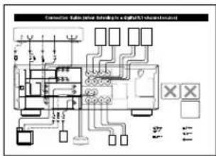
■Att observera angående batterier
⑦BASS EXTENSION ON/OFF
1 Lossa skruvknoppen.
Observera
JUSTERING AV HÖGTALARNAS UTNIVÅER
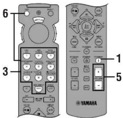
→[A] ····· DVD [B] ····· D-TV/CBL

→[A] ····· VCR 1 [B] ····· D-TV/CBL

SML
NONE
SMALL
Observera
SML

MAIN
Observera
flowchart
graph TD
    A["Hand pointing at 'TITLE' circle"] --> B["Arrow pointing right"]
    B --> C["Diagram with directional arrows and labels: 0°, 30°, 60°, 90°, +"]
    C --> D["Hand pointing at 'LEVEL' circle"]
flowchart
graph LR
    A["Circle Component"] --> B["Rectangular Device"]
    B --> C["Control buttons: Open, Close, Save, Cancel"]
2 Mata in kod nummer "9990".
■DTS (Digital Theater Systems) Digital Surround
Minnes-backup 32, 38, 51
natural_image
Line drawing of four cylindrical batteries with battery terminals (no text or symbols)⑦BASS EXTENSION ON/OFF
Spinotto a banana
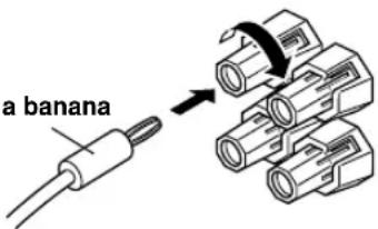
MESSAGGI SULLO SCHERMO (OSD)
Note
SML
NONE
SMALL
Nota
SML

MAIN
Note
-10 dB
natural_image
Simple line drawing of a refrigerator inside a circular frame (no text or symbols)■ S.DELAY (ritardo surround)
8/6/4/2 Ω 120/140/175/210 W
DISPLAY SET (SET MENU)
BLUE BACK.... 37
DIMMER 37
OSD SHIFT 37
DOLBY D. SET (SET MENU)
D-RANGE 36
LFE LEVEL 36
Dolby Digital 60
Dolby Surround (Dolby Pro Logic).... 60
DTS 60
DTS SET (SET MENU) 36
F
I/O ASSIGNMENT (SET MENU).... 35,61
INPUT MODE (SET MENU) 35
SPEAKER SET (SET MENU)
CENTER SP 32
LFE/BASS OUT.... 34
MAIN LEVEL.... 34
MAIN SP 33
REAR L/R SP....33
Subwoofer.... 17
T
natural_image
Line drawing of four cylindrical batteries with battery terminals (no text or symbols)⑦BASS EXTENSION ON/OFF
→ INIT. DLY....45ms ROOM SIZE 1.0. LIVENESS....5
P01 CONCERT HALL
Notas
Panel delantero
Nota
1 Pulse DSP PROGRAM.

SET MENU 1/3
1 SPEAKER SET
2 L/R BALANCE
3 HP TONE CTRL
4 I/O ASSIGNMENT
▲/▼: Up/Down
-/+ : Enter

flowchart
graph TD
    A["4A CMPNT-V INPUT"] --> B["VCR 1"]
    A --> C["D-TV/CBL"]
SML
NONE
SMALL
Nota
[Non-Text]
-10 dB
(3) DVD
(4) D-TV/CBL
4C OPTICAL IN
AUTO
Gama de control (ms): de 0 a 5
Ajuste inicial: 0 ms
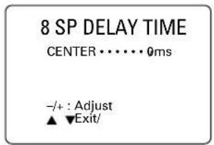
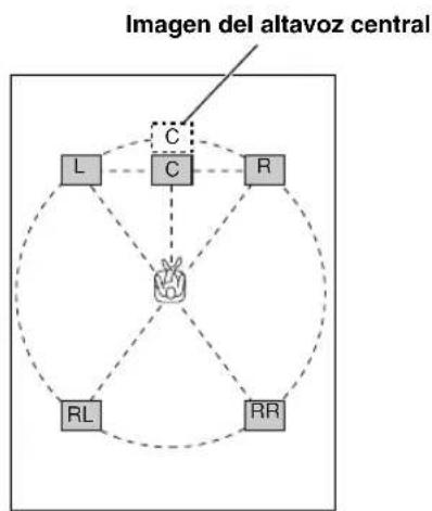
flowchart
graph TD
    A["C"] --> B["L"]
    A --> C["C"]
    A --> D["R"]
    A --> E["RL"]
    A --> F["RR"]
    G["Imagen del altavoz central"] --> A
    style A fill:#f9f,stroke:#333
    style B fill:#ccf,stroke:#333
    style C fill:#cfc,stroke:#333
    style D fill:#fcc,stroke:#333
    style E fill:#cff,stroke:#333
    style F fill:#ffc,stroke:#333

DISPLAY SET (SET MENU)
BLUE BACK 37
DIMMER 37
OSD SHIFT 37
DOLBY D. SET (SET MENU)
D-RANGE 36
LFE LEVEL 36
Dolby Digital 60
Dolby Surround (Dolby Pro Logic) 60
DTS 60
DTS SET (SET MENU) 36
E
Enmudecimiento 25
F
I/O ASSIGNMENT (SET MENU).... 35, 61
INPUT MODE (SET MENU) 35
Interruptor IMPEDANCE SELECTOR 19
L
LFE 36,60
M
MEMORY GUARD (SET MENU) 37
Modos de entrada 26
P
Panel delantero 4
Panel trasero 10
PCM....61
Posición CBL/SAT 44
Posición CD 42
Posición DVD/LD 43
SPEAKER SET (SET MENU)
CENTER SP 32
LFE/BASS OUT 34
MAIN LEVEL 34
MAIN SP 33
REAR L/R SP....33
T
natural_image
Simple line drawing of a trash bin with a cross symbol on the handle (no text or labels)INHOUD
INLEIDING
EIGENSCHAPPEN 2
VOOR GEBRUIK 3
CINEMA DSP-programma's 47
INSTELLEN VAN DE
GELUIDSVELDPROGRAMMAPARAMETERS 50
natural_image
Line drawing of four cylindrical batteries with visible battery caps (no text or symbols)■Opmerkingen betreffende de batterijen
⑦BASS EXTENSION ON/OFF
⑧DSP-programma-indicators
⑫ IMPEDANCE SELECTOR-schakelaar
Opmerkingen
VCR 1: Videorecorder 1
VCR 2/DVR: Videorecorder 2/digitale videorecorder
Opmerking
flowchart
graph TD
    A["DSP PROGRAM"] --> B["Voorpaneel of"]
    C["DSP"] --> D["Afstandsbediening"]
    B --> E["Control buttons: HALL CO, JUST TUNER, MODE MO/CDAR, 1, 2, 3, 4, 5, 6, 7, 8, 9"]
    D --> F["Control buttons: 1,2,3,4,5,6,7,8,9,10,11,12,13,14,15,16,17,18,19,20,21,22,23,24,25,26,27,28"]
flowchart
graph TD
    A["Outer Zone"] --> B["Inner Zone"]
    B --> C["Outer Zone"]
    C --> D["Inner Zone"]
    D --> E["Outer Zone"]
    E --> F["Inner Zone"]
    F --> G["Outer Zone"]
    G --> H["Inner Zone"]
    H --> I["Outer Zone"]
    I --> J["Inner Zone"]
    J --> K["Outer Zone"]
    K --> L["Inner Zone"]
    L --> M["Outer Zone"]
    M --> N["Inner Zone"]
    N --> O["Outer Zone"]
    O --> P["Inner Zone"]
    P --> Q["Outer Zone"]
    Q --> R["Inner Zone"]
    R --> S["Outer Zone"]
    S --> T["Inner Zone"]
    T --> U["Outer Zone"]
    U --> V["Inner Zone"]
    V --> W["Outer Zone"]
    W --> X["Inner Zone"]
    X --> Y["Outer Zone"]
    Y --> Z["Inner Zone"]
SET MENU 1/3
1 SPEAKER SET 2 L/R BALANCE 3 HP TONE CTRL →4 I/O ASSIGNMENT ▲/▼ : Up/Down -/+ : Enter

SML (klein)
NONE (geen)
SMALL (klein)
Opmerking

Opmerkingen
-10 dB
→[A] ····· DVD [B] ····· D-TV/CBL
(3) DVD (4) D-TV/CBL
4C OPTICAL IN
→ BLUE BACK ···· AUTO OSD SHIFT ······ 0 DIMMER ······ ···· 0
■Stand TAPE/MD (tapedeck, md-recorder of cd-recorder)
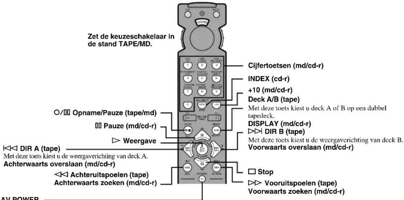
flowchart
graph LR
    A["Control Panel 1"] --> B["Directional Arrow"]
    B --> C["Control Panel 2"]
Hifi DSP-programma's
CINEMA DSP-programma's
■S.INIT.DLY (surround-beginvertraging)
■DTS (Digital Theater Systems) Digital Surround
DISPLAY SET (SET MENU)
BLUE BACK 37
DIMMER 37
OSD SHIFT 37
DTS SET (SET MENU) 36
DVD/LD-stand 43
DVD MENU-stand 43
E
Externe decoder 18
F
Fabrikantcodes 45, i
G
I/O ASSIGNMENT (SET MENU) 35,61
IMPEDANCE SELECTOR-schakelaar.... 19
Ingangsfuncties 26
INPUT MODE (SET MENU) 35
K
SPEAKER SET (SET MENU)
CENTER SP 32
LFE/BASS OUT 34
MAIN LEVEL 34
MAIN SP 33
REAR L/R SP 33
Stereoweergave 29
Stofkapje 12
Subwoofer.... 17
S VIDEO signal 61
T
TAPE/MD-stand 42
Testtoon (TEST DOLBY SUR.).... 22
TV-stand 44
V
VCR-stand 44
Vertragingstijd 37
GBC 0021,0141,1321, 1511,1621,1981
GEC 0451, 1101, 1281, 2321
GEC (UK) 0031, 0081, 0581, 0601, 1101, 1281, 1561
GELOSO 0021, 0411, 0451, 1321, 1511, 1621, 1981
ITT 0031,0041,0051, 0061,0071,0081, 0181,0411,0451, 0491,1241,1291, 1351,1501,1601, 1641,1741,1921, 1981,2091,2331, 2431
ITT-NOKIA 0031, 0041, 0051, 0061, 0071, 0081, 0181, 0411, 0451, 0491, 1241, 1291, 1351, 1501, 1601, 1641, 1741, 1921, 1981, 2091, 2331, 2431
JVC (VICTOR) 0071, 0721, 1441, 1581, 1591, 1741, 1791
KAISUI 0591, 1321, 1331
KAMOSONIC 0601
KARCHER 0591, 0601, 0841, 1091, 1321, 1511, 1561, 2051
KAWASHO 0761
KENDO 0261
KENNEDY 0021, 0351, 0951, 1981
KONKA 2701
KORTING 0431, 1011, 1021, 1081, 1541
| KTV 0601, 1171 | |
| LENOIR 0601, 1511 | |
| LEYEO 1181 | |
| LIFETEC 2591, 2601, 2611,2621, 2641, 2651,2661, 2671, 2681,2691, 2711, 2761,2771, 2781 | |
| LOEWE OPTA 0121, 0131, 0581,0611, 1081 | |
| LOGIC 1691, 2281 | |
| LOGIK 0551, 1681, 2281 | |
| LOWEWE 0831 | |
| LUMA 0351, 0451, 1901 | |
| LUXMAN 0791 | |
| LUXMAN STEREO TUNER | |
| 0791 | |
| LUXOR 0001, 0061, 0181,0341, 0421, 0451,0461, 0491, 0601,0671, 1351, 1371,1561, 1601, 1911,1921, 1981 | |
| LYCO 1181 | |
| MAGNADYNE 0021, 0061, 0261,0581, 0641, 0771,1021, 1081, 1621,1981 | |
| MAGNAFON 0261, 0491, 0581,0591, 0641, 0761,1091, 2001 | |
| MANESTH 0101 | |
| MARANTZ 0101 | |
| MARELLI 1081 | |
| MARK 0101 | |
| MATSUI 0061, 0451, 0601,0691, 1101, 1151,1241, 1271, 1301,1511, 1561, 1681,1691 | |
| MAXIMAL 0071, 1981 | |
| MCMICHAEL 1281 | |
| MEDION 2591, 2601, 2611,2621, 2641, 2651,2661, 2671, 2681,2691, 2711, 2721,2761, 2771, 2781 | |
| MEMOREX 1511 | |
| METZ 0231, 0741, 1001,1041, 1081, 1481,2071, 2081 | |
| MGA 1231 | |
| MICROMAXX 2591, 2621, 2641,2651, 2711, 2761,2771, 2781 | |
| MINERVA 0221, 0231, 0491,1381, 2141, 2151 | |
| MISTRAL 2281 | |
| MITSUBISHI 0141, 0201, 0231,0661, 1191, 1201,1231, 1671, 1691,1741 | |
| MIVAR 0491, 0501, 0581,0591, 0761, 0771,1371, 1431, 2031 | |
| MTC 0791 | |
| MULTITECH 0261, 0581, 0601,0641, 0981, 1321,1511 | |
| MURPHY 0451, 2091 | |
| MURPHY (UK) 0081, 1031 | |
| N.E.I. 0101, 0961 | |
| NAD 1341 | |
| NEC 0141, 1711, 1721,1731 |
| NECKERMANN | 0451, 0601, 0981, 1081, 1561, 1931, 1981, 2211, 2231, 2241 |
NEDIATOR 0101
| NICAMAGIC 0761 | |
| NIKKAI | 1101, 1331, 1641, 1701, 2011 |
| NOBLIKO | 0261, 0491, 0591, 0641, 1381, 1411 |
NOGAMATIC 0571
| NOKIA | 0031, 0041, 0051, 0061, 0071, 0081, 0181, 0411, 0451, 0491, 1241, 1291, 1351, 1501, 1601, 1641, 1741, 1921, 1981, 2091, 2331, 2431, 2461, 2791 |
| NORDMENDE | 0031, 0291, 0331, 0451, 0531, 0541, 0571, 1051, 1131, 1591, 1791, 1811, 1821, 1891, 1941, 2631 |
OCEANIC 0321, 1651, 1981
| OCEANIC (F) | 0031, 0061, 0321, 0441, 1661 |
ONCEAS 0601
| ONWA | 1171 |
| ORION | 0061, 0391, 0691, 0851, 1211, 1241, 1251, 1301, 1481, 1511, 1681, 1691, 1981, 2371, 2421 |
OSAKA 2011
| OSAKI 1101, 1331, 2011 | |
| OSUME | 0151 |
| OTTO VERSAND | 0021, 0121, 0141, 0221, 0601, 1561, 1741, 1981 |
PAEL 0591,1411
| PANASONIC | 0031, 0201, 0211, 0451, 0701, 1311, 1751, 1961, 2561, 2741 |
PANORAMIC 2351
| PATHE MARCONI | 0571 |
| PATHE' CINEMA (F) | 0431, 0591, 1621, 1661, 1971 |
PAUSA 1511
| PAUZA | 1511 |
| PERDIO 0891, 1101 | |
| PHILCO 0021, 0491, 0811, | |
| 0981, 1021, 1081, | |
| 1401, 1611, 1621, | |
| 1751, 2201, 2251, | |
| 2271, 2451, 2471 | |
| PHILIPS 0101, 0361, 0591, |
| 0621, 0681, 0751, |
| 0761, 1021, 1081, |
| 1281, 2031, 2281, |
| 2291, 2431, 2441, |
| 2511, 2731 |
PHOENIX 1081
| PHONOLA | 0751, 1081 |
| PIONEER | 0291, 0451, 1341, 1821 |
| PRANDONI-PRINCE | 0411, 0451, 0491, 0581, 1411 |
| PRANDONI-PROMCE0451, 0491, 0581 |
| PRIMA | 0451 |
| PROFEX | 1981 |
| PROTECH | 0641, 1181, 1981 |
| QUELLE | 0041, 0061, 0121, 0221, 0231, 0391, 0491, 0521, 0601, 0781, 1371, 1381, 1411, 1421, 1641, 1681, 2051, 2091, 2141, 2151, 2201, 2211, 2231, 2241, 2251, 2271, 2551, 2571, 2581 |
| REDIOMARELLI | 0101, 0451, 0661, 0771, 1081 |
| RADIONETTE | 0031, 2051, 2091 |
| RADIOLA | 2291 |
| RANK | 0481, 2151 |
| RBM | 2131, 2151 |
| RBM (UK) | 0481 |
| REDIFFUSION | 0451, 0661, 1641, 1981, 2331 |
| REDIFFUSION (UK) | 0061, 0081, 1031 |
| REX | 0071, 0101, 0351, 0411, 0451, 0951, 1901, 2061, 2101, 2111 |
| RFT | 0991, 2511 |
| ROADSTAR | 1321, 1511 |
| ROTEL | 0151 |
| SABA 0291, 0331, 0421, 0451, 0531, 0541, 0571, 0581, 0651, 0731, 0931, 1021, 1071, 1081, 1131, 1791, 1811, 1821, 1891, 1941, 2631 | |
| SACCS | 1971 |
| SAISHO | 0451, 0601, 1161, 1241, 1301, 1511, 1671, 1681, 1691 |
| SALORA 0011, 0041, 0061, 0071, 0341, 0451, 0671, 1291, 1351, 1521, 1561, 1601, 1641, 1911, 1921, 1931, 1981, 2321 | |
| SAMBERS | 0261, 0491, 0581, 0641, 1091, 1371, 1411, 2001 |
| SAMSUNG | 0101, 0601, 0841, 0981, 1101, 1181, 1371, 1511, 2011 |
| SANYO 0141, 0151, 0401, 0601, 0801, 0821, 0981, 1021, 1101, 1111, 1291, 1351, 1691, 1741, 2051, 2091, 2551 | |
| SBR | 0681, 0751, 1281, 2281 |
| SCHAUB LORENZ | 0451 |
| SCHNEIDER | 0021, 0071, 0091, 0451, 0511, 0591, 0601, 0751, 1321, 1361, 1621, 1641, 2101, 2111, 2291 |
| SCOTT | 1171, 1261 |
| SEG | 0261, 0601, 0821, 0991 |
| SEI | 0641, 0691, 1081, 1301, 1481, 1981 |
| SELECO | 0071, 0101, 0351, 0411, 0451, 0951, 1901, 2061, 2101, 2111 |
| SENTRA | 1601 |
| SHARP | 0141, 0151, 0191, 1761, 1781 |
| SIAREM | 0021, 0261, 0581, 0641, 1021, 1081, 1981 |
| SICATEL 1971 | |
| SIEMENS | 0151, 0221, 0231, 0451, 0741, 2011, 2201, 2211, 2221, 2231, 2241, 2261, 2571, 2581 |
| SILVER | 1181 |
| SINGER 0021, 0261, 1021, 1081 | |
| SINUDYNE | 0021, 0061, 0101, 0261, 0391, 0641, 0691, 0851, 0941, 1021, 1081, 1241, 1301, 1321, 1481, 1631, 1981 |
| SKANTIC 0451 | |
| SOLAVOX | 0451, 1641, 2011 |
| SONOKO | 0101, 1181, 1511 |
| SONY | 0141, 0171, 1121, 1681, 1691, 2751 |
| SOUNDESIGN | 1171 |
| SSS | 1171 |
| STERN | 0071, 0101, 0351, 0411, 0451, 0951, 1901, 2061, 2101, 2111 |
| SUNKAI | 0691 |
| SUPRA | 0791 |
| TANDBERG | 0161, 0331, 0611, 1021, 1421, 1771, 1791, 2081 |
| TANDY | 0191, 0451, 1331, 1531 |
| TASHIKO | 0141 |
| TATUNG | 0271, 0581, 0601, 0971, 1101, 1681, 1691 |
| TCM | 2621, 2641, 2711, 2761, 2771, 2781 |
| TECHNICS | 1311 |
| TECHWOOD | 0791 |
| TEKNIKA | 1171, 1231, 1261 |
| TELE | 1141 |
| TELEAVIA | 0571, 0651, 0731, 1821 |
| TELEFUNKEN | 0291, 0301, 0311, 0551, 0731, 1131, 1471, 1591, 1791, 1801, 1811, 1821, 1991, 2161, 2171, 2181, 2191, 2201, 2251, 2271, 2521, 2631 |
| TELETECH | 1511 |
| TEMPEST | 2381, 2391, 2401, 2411 |
| TENSAI | 1331, 2091 |
| TEXET | 0601 |
| THOMSON | 0331, 0481, 0531, 0571, 0631, 0651, 0731, 0901, 1241, 1571, 1591, 1791, 1811, 1821, 1891, 1941, 2531 |
| THORN 0741, 0861, 2091,2251, 2271, 2281 |
| THORN-FERGUSON 0281, 0371, 0551, 0651, 0781, 0861, 0881, 1131, 1181, 1361, 1461, 1971, 1991, 2281 |
TMK 0141, 0791, 1471
| TOSHIBA 0141, 0381, 0481,1221, 1271, 1701,1741, 1851, 2151,2801, 2811 |
TRANS CONTINENS 0451
| TRISTAR 2281 |
| TRIUMPH 0481, 0581, 2121 |
| UHER 0431, 0451, 0481,0491, 0511, 1311,1541 |
ULTRAVOX 0021, 0261, 0591, 1021, 1081, 1981
| UNIVERSUM 1181, 2051 |
| UNIVOX 1971 |
| VEGAVOX 0811 |
| VEXA 0101, 1511 |
| VIDEOTON 2481 |
| VORTEC 0101, 0651 |
| VOXSON 0411, 0451, 0491, 1021, 1081 |
WALTHAM 0451
| WATSON | 0431, 2201, 2241 |
| WATT RADIO | 0021, 0061, 0261, 0591, 0641, 0761, 1091, 1971, 1981, 2001 |
WEGA 0141, 1081, 1981
| WEGA COLOR 1021 |
| WELTBLICK 0101 |
WESTON 1621
| WHITE WESTINGHOUSE |
| 0101, 0261, 0431, |
| 0591, 0761, 1401, |
| 1541 |
YOKO 0601,1511
| ZANUSSI | 0071, 0101, 0351, 0411, 0451, 0951, 1901, 2061, 2101, 2111 |
| ZOPPAS | 0451 |
CABLE TV
CABLETIME 1446, 1456, 1476
| CLYDE CABLEVISION1426 |
FILMNET 1396, 1436
FRANCE TELECOM 1386
| GEC | 1426 |
JERROLD 1416
MOVIE TIME 1466
NSC 1466
PHILIPS 1386
PIONEER 0006
SAMSUNG 1496
SCIENTIFIC ATLANTA
1486, 1506
STARCOM 1416
STS 1466
TANDBERG 1366
TELE 1436
TELE +1 1436
TELESERVICE 1406, 1476
TUDI 1376
UNITED CABLE 1416
ZENITH 1406
SATELLITE TUNER
| AKAI | 1276 |
| ALBA 0826, 1276 | |
| AMSTRAD | 0166, 0796, 1016, 1026, 1296 |
ANKARO 0476
AST 0406
ASTRA 0126
BARCOM 0476
BLAUPUNKT 0966
BMC SATELLITE 0106
BRITISH TELECOM 1276
BUSH 0826
BUSH (UK) 0956
CAMBRIDGE 0196, 1276
CANAL PLUS (FRANCE)
1536
CHAPARRAL 0016, 0696, 1006
COLUMBUS 0616
CONNEXIONS 0306, 0426
DISCUS ELIPSE 0856, 0866
DISKXPRESS 0426, 0476
DRAKE 1516
| ECHOSTAR | 0226, 0236, 0606, 0626, 0666, 0926, 0996, 1046, 1056, 1066, 1106 |
ELTA 1286
ELTA SAT 0146
EURODEC 1226, 1236, 1246
| FERGUSON 0046, 0176, 0186,0296, 0846, 0956,1306 |
FINLUX 0976
FRACARRO 0026, 0536, 0776
| FUBA | 0476, 0616, 0636, 1056 |
GIUCAR RECORD 0206, 0336
| GRUNDIG | 0176, 0946, 0956, 0966 |
HIGH PERFORMANCE
0916
HIRSCHMANN 0756, 0966
| HITACHI | 0446, 0516, 0706, 0946 |
ICX INTERNATIONAL 0886
| ITT | 0066, 0126, 0176, 0446, 1156 |
ITT/NOKIA 0066, 0126, 0176,
0446, 1156
JEEMON 0146
JERROLD 0846,0986
JOHANSSON 0246
JVC 1276
| KATHREIN | 0116, 0266, 0276, 0366 |
KOSMOS 0266
KYOSTAR 1036, 1086
LENG 0246
LIFESAT 1326, 1346, 1356
| LUXOR | 0126, 0136, 0446, 0466, 0506, 1156 |
MACAB 0356
MASPRO 0016, 0116, 0256, 0956
| MEDION | 1326, 1346 |
METZ 0966
MICROMAXX 1326, 1346
Connection Guide (when listening to a digital 5.1-channel source)
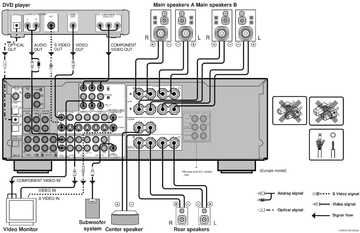
flowchart
graph TD
    A["Main speakers A Main speakers B"] -->|R+/-| B["Component Video Out"]
    A -->|L+/-| C["Component Video IN"]
    A -->|L+/-| D["Subwoofer system"]
    A -->|L+/-| E["Center speaker"]
    A -->|L+/-| F["Rear speakers"]
    B --> G["Main speakers A"]
    C --> H["Main speakers B"]
    D --> I["Subwoofer system"]
    E --> J["Center speaker"]
    F --> K["Rear speakers"]
    style A fill:#f9f,stroke:#333
    style B fill:#ccf,stroke:#333
    style C fill:#cfc,stroke:#333
    style D fill:#fcc,stroke:#333
    style E fill:#cff,stroke:#333
    style F fill:#ffc,stroke:#333
    style G fill:#fff,stroke:#333
    style H fill:#fff,stroke:#333
    style I fill:#fff,stroke:#333
    style J fill:#fff,stroke:#333
    style K fill:#fff,stroke:#333
V720170 DSP-AX620
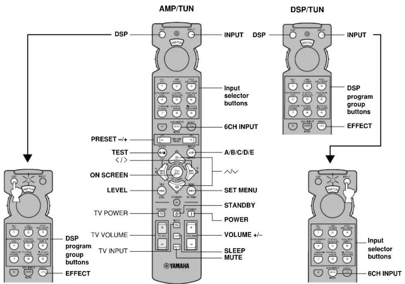
flowchart
graph TD
    A["AMP/TUN"] --> B["DSP"]
    A --> C["DSP/TUN"]
    B --> D["INPUT"]
    C --> E["INPUT"]
    D --> F["6CH INPUT"]
    E --> G["DSP program group buttons"]
    E --> H["EFFECT"]
    F --> I["PRESET -/+"]
    F --> J["TEST </><"]
    F --> K["ON SCREEN"]
    F --> L["LEVEL"]
    F --> M["TV POWER"]
    F --> N["TV VOLUME"]
    F --> O["TV INPUT"]
    F --> P["YAMAHA"]
    G --> Q["A/B/C/D/E"]
    H --> R["SET MENU"]
    H --> S["STANDBY"]
    H --> T["POWER"]
    H --> U["VOLUME +/-"]
    H --> V["SLEEP MUTE"]
    I --> W["6CH INPUT"]
    J --> X["6CH INPUT"]
    K --> Y["6CH INPUT"]
    L --> Z["6CH INPUT"]
    M --> AA["6CH INPUT"]
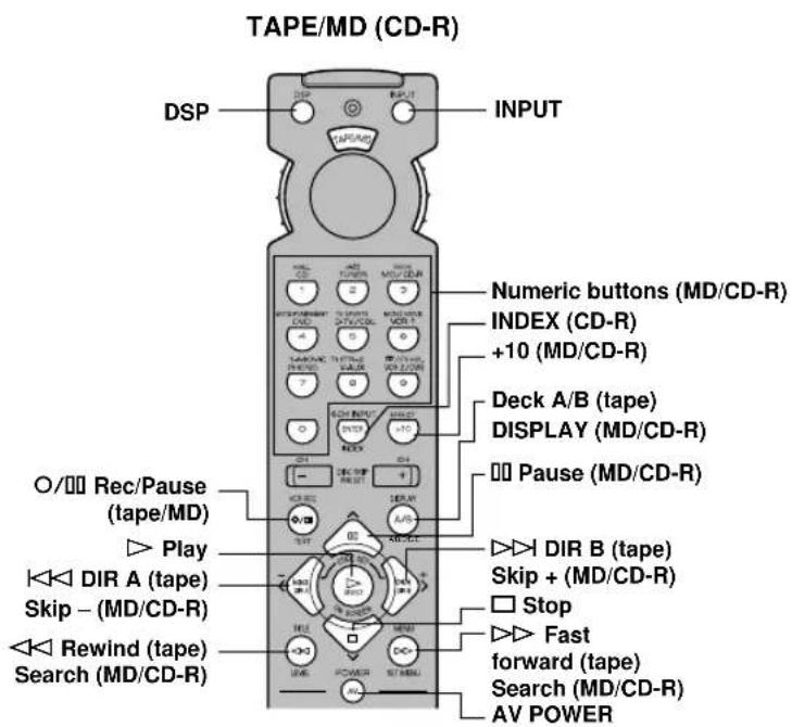
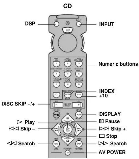
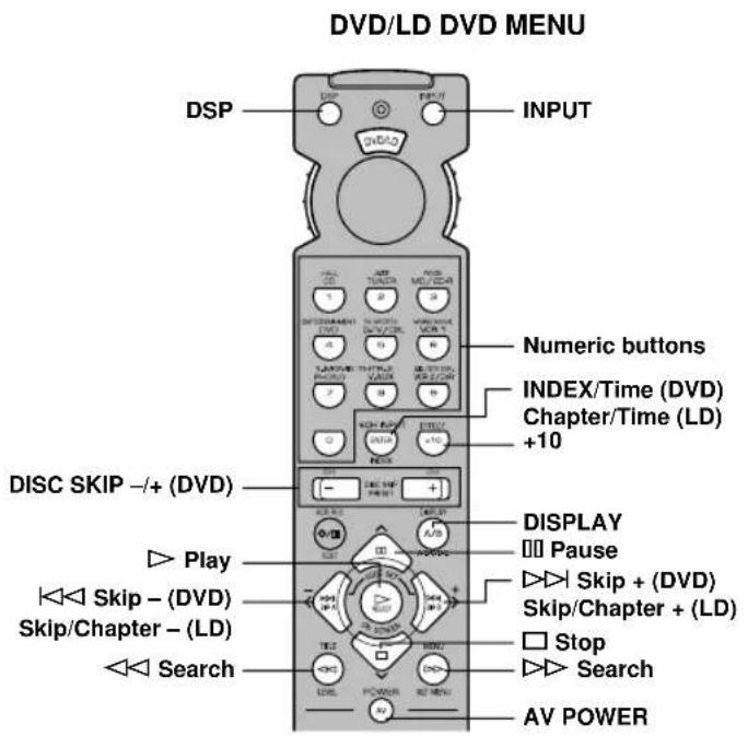
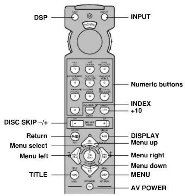
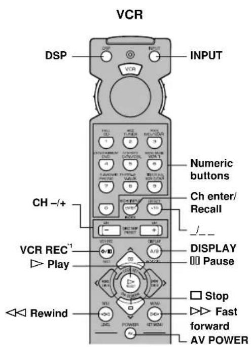
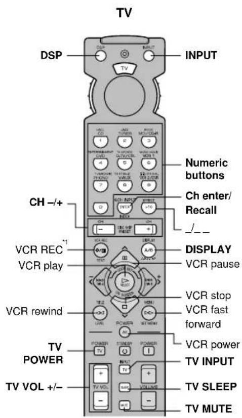
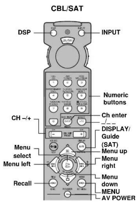
*1 Presentista le molte pericsto stato precordizire la registrazione.
Appuyer deux fois sur cette touche pour commencer l'enregistrement.
Drücken Sie diese Taste zweimal, um die Aufnahme zu starten.
Tryck två gånger på den här knappen för att börja spela in.
Presione dos veces este botón para empezar a grabar.
Druk tweemaal op deze toets om met opnemen te beginnen.
按此按钮两次即可开始录像。


