
RXV757 - Home cinema amp YAMAHA - Free user manual and instructions
Find the device manual for free RXV757 YAMAHA in PDF.

| Product Type | Home Theater Amplifier |
| Brand | YAMAHA |
| Model | RXV757 |
| Dimensions (W x H x D) | 435 x 171 x 420 mm |
| Weight | 12.5 kg |
| Power Supply | AC 230 V, 50 Hz (European model); 110-240 V, 50/60 Hz depending on version |
| Output Power (7 channels) | 100 W per channel (20 Hz – 20 kHz, 0.06% THD, 8 Ω) |
| Supported Audio Formats | Dolby Digital, Dolby Digital EX, DTS, DTS-ES, DTS Neo:6, DTS 96/24, Dolby Pro Logic II/IIx, PCM |
| Sound Field Programs | CINEMA DSP, HiFi DSP, Virtual CINEMA DSP, SILENT CINEMA |
| YPAO Function | Automatic speaker calibration (impedance, distance, level, equalization) |
| Pure Direct Mode | Bypasses DSP circuits for Hi-Fi listening |
| Audio Inputs | 8 analog inputs (including Phono), 2 optical, 2 coaxial, 1 multi-channel input (8 channels) |
| Audio Outputs | 7 speaker terminals (A/B front, center, surround, surround back), pre-out front/center/surround/subwoofer, zone 2 (RX-V757), headphone |
| Video Inputs | Composite, S-Video, Component (Y, Pb, Pr) |
| Video Outputs | Composite, S-Video, Component (with conversion) |
| Radio | AM/FM with 40 presets (RX-V757) |
| Remote Control | Infrared, programmable with learning |
| Listening Modes (Night) | NIGHT:CINEMA, NIGHT:MUSIC (dynamic compression) |
| Sleep Timer | Yes (SLEEP) |
| Memory Backup | Approximately 1 week after disconnection |
| Maintenance and Cleaning | Dry, clean cloth; avoid chemical solvents |
| Safety | Do not expose to moisture; unplug during thunderstorms; do not open the casing |
| Repairability | Consult an authorized YAMAHA service center; no user-repairable parts |
Frequently Asked Questions - RXV757 YAMAHA
User questions about RXV757 YAMAHA
0 question about this device. Answer the ones you know or ask your own.
Ask a new question about this device
Download the instructions for your Home cinema amp in PDF format for free! Find your manual RXV757 - YAMAHA and take your electronic device back in hand. On this page are published all the documents necessary for the use of your device. RXV757 by YAMAHA.
USER MANUAL RXV757 YAMAHA
1 To assure the finest performance, please read this manual carefully. Keep it in a safe place for future reference.
2 Install this sound system in a well ventilated, cool, dry, clean place - away from direct sunlight, heat sources, vibration, dust, moisture, and/or cold. Allow ventilation space of at least 30~cm on the top, 20~cm on the left and right, and 20~cm on the back of this unit.
3 Locate this unit away from other electrical appliances, motors, or transformers to avoid humming sounds.
4 Do not expose this unit to sudden temperature changes from cold to hot, and do not locate this unit in a environment with high humidity (i.e. a room with a humidifier) to prevent condensation inside this unit, which may cause an electrical shock, fire, damage to this unit, and/or personal injury.
5 Avoid installing this unit where foreign object may fall onto this unit and/or this unit may be exposed to liquid dripping or splashing. On the top of this unit, do not place:
- Other components, as they may cause damage and/or discoloration on the surface of this unit.
- Burning objects (i.e. candles), as they may cause fire, damage to this unit, and/or personal injury.
- Containers with liquid in them, as they may fall and liquid may cause electrical shock to the user and/or damage to this unit.
6 Do not cover this unit with a newspaper, tablecloth, curtain, etc. in order not to obstruct heat radiation. If the temperature inside this unit rises, it may cause fire, damage to this unit, and/or personal injury.
7 Do not plug in this unit to a wall outlet until all connections are complete.
8 Do not operate this unit upside-down. It may overheat, possibly causing damage.
9 Do not use force on switches, knobs and/or cords.
10 When disconnecting the power cord from the wall outlet, grasp the plug; do not pull the cord.
11 Do not clean this unit with chemical solvents; this might damage the finish. Use a clean, dry cloth.
12 Only voltage specified on this unit must be used. Using this unit with a higher voltage than specified is dangerous and may cause fire, damage to this unit, and/or personal injury. YAMAHA will not be held responsible for any damage resulting from use of this unit with a voltage other than specified.
13 To prevent damage by lightning, disconnect the power cord and outdoor antenna from the wall outlet during an electrical storm.
14 Do not attempt to modify or fix this unit. Contact qualified YAMAHA service personnel when any service is needed. The cabinet should never be opened for any reasons.
15 When not planning to use this unit for long periods of time (i.e. vacation), disconnect the AC power plug from the wall outlet.
16 Be sure to read the "TROUBLESHOOTING" section on common operating errors before concluding that this unit is faulty.
17 Before moving this unit, press STANDBY/ON to set this unit in the standby mode, and disconnect the AC power plug from the wall outlet.
WAR NING
TO REDUCE THE RISK OF FIRE OR ELECTRIC SHOCK,DO NOT EXPOSE THIS UNIT TO RAIN OR MOISTURE.
This unit is not disconnected from the AC power source as long as it is connected to the wall outlet, even if this unit itself is turned off. This state is called the standby mode. In this state, this unit is designed to consume a very small quantity of power.
■For U.K. customers
If the socket outlets in the home are not suitable for the plug supplied with this appliance, it should be cut off and an appropriate 3 pin plug fitted. For details, refer to the instructions described below.
Note
The plug severed from the mains lead must be destroyed, as a plug with bared flexible cord is hazardous if engaged in a live socket outlet.
Special Instructions for U.K. Model
IMPORTANT
THE WIRES IN MAINS LEAD ARE COLOURED IN ACCORDANCE WITH THE FOLLOWING CODE:
Blue: NEUTRAL Brown: LIVE
As the colours of the wires in the mains lead of this apparatus may not correspond with the coloured markings identifying the terminals in your plug, proceed as follows:
The wire which is coloured BLUE must be connected to the terminal which is marked with the letter N or coloured BLACK. The wire which is coloured BROWN must be connected to the terminal which is marked with the letter L or coloured RED.
Making sure that neither core is connected to the earth terminal of the three pin plug.
CONTENTS
INTRODUCTION
FEATURES. 2
GETTING STARTED. 3
Supplied accessories 3
Installing batteries in the remote control 3
CONTROLS AND FUNCTIONS 4
Front panel. 4
Remote control. 6
Using the remote control 7
Front panel display 8
Rear panel 10
PREPARATION
SPEAKER SETUP 11
Speaker placement. 11
Speaker connections 12
CONNECTIONS 15
Before connecting components. 15
Connecting video components. 16
Connecting audio components. 19
Connecting the FM and AM antennas (RX-V757 only) 21
Connecting the power supply cord 22
Speaker impedance setting 23
Turning on the power 23
AUTO SETUP 24
Introduction 24
Optimistic and pessimistic 24
Optimizer microphone setup. 24
Starting the setup 25
BASIC OPERATION
PLAYBACK. 30
Basic operations 30
Selecting sound field programs 32
Selecting input modes 37
FM/AM TUNING (RX-V757 ONLY) 39
Automatic and manual tuning. 39
Preseting stations. 40
Selecting preset stations. 42
Exchanging preset stations 43
Receiving Radio Data System stations. 44
Changing the Radio Data System mode 45
PTY SEEK function 46
EON function. 47
RECORDING 48
SOUND FIELD PROGRAMS
SOUND FIELD PROGRAM
DESCRIPTIONS. 49
For movie/video sources. 49
For music sources 51
ADVANCED OPERATION
Selecting the OSD mode 52
Using the sleep timer 52
Manually adjusting speaker levels. 53
SET MENU. 54
Using SET MENU 56
1 SOUND MENU. 57
2 INPUT MENU 62
3 OPTION MENU 64
ADVANCED SETUP MENU. 66
REMOTE CONTROL FEATURES 68
Control area 68
Setting remote control codes 69
Controlling other components 71
Programming codes from other remote controls ....72
Changing source names in the display window..... 73
Clearing function sets 74
Clearing individual functions 75
ZONE 2 (RX-V757 ONLY) .76
Zone 2 connections. 76
Remote controlling Zone 2 77
ADDITIONAL INFORMATION
EDITING SOUND FIELD PARAMETERS ....79
What is a sound field 79
Changing parameter settings 79
SOUND FIELD PARAMETER
DESCRIPTIONS. 81
TROUBLESHOOTING 86
RESETTING THE FACTORY PRESETS.91
GLOSSARY 92
AUDIO 92
Audio formats 92
Sound field programs. 93
Audio information 93
Video signal information 94
SPECIFICATIONS. 95
FEATURES
Built-in 7-channel power amplifier
Minimum RMS output power (0.06%) THD, 20Hz to 20kHz,8
Front: 100W + 100W Center: 100W
Surround: 100W + 100W Surround back: 100W + 100W
Sound field features
Proprietary YAMAHA technology for the creation of sound fields
Dolby Digital/Dolby Digital EX decoder
DTS/DTS-ES Matrix 6.1, Discrete 6.1, DTS Neo:6, DTS 96/24 decoder
Dolby Pro Logic/Dolby Pro Logic II/ Dolby Pro Logic IIx decoder
Virtual CINEMA DSP
SILENT CINEMA
Sophisticated AM/FM tuner (RX-V757 only)
40-station random and direct preset tuning
Automatic preset tuning
Preset station shifting capability (preset editing)
Other features
YPAO:YAMAHA Parametric Room Acoustic Optimizer for automatic speaker setup
192-kHz/24-bit D/A converter
A SET MENU that provides you with items for optimizing this unit for your audio/video system
8 additional input jacks for discrete multi-channel input
PURE DIRECT for pure fidelity sound with analog and PCM sources
On-screen display function helpful in controlling this unit
S-video signal input/output capability
Component video input/output capability
Video signal conversion (Composite video S-video Component video) capability for monitor out
Optical and coaxial digital audio signal jacks
Sleep timer
Cinema and music night listening modes
Remote control with preset remote control codes and "learning" capability
Zone 2 custom installation facility (RX-V757 only)
This document is the owner's manual for both RX-V757 and DSP-AX757SE. Model names are given where the details of functions are unique to each model. Illustrations for RX-V757 are mainly used for explanations.
- y indicates a tip for your operation.
- Some operations can be performed by using either the buttons on the main unit or on the remote control. In cases when the button names differ between the main unit and the remote control, the button name on the remote control is given in parentheses.
This manual is printed prior to production. Design and specifications are subject to change in part as a result of improvements, etc. In case of differences between the manual and product, the product has priority.

Manufactured under license from Dolby Laboratories.
"Dolby", "Pro Logic", "Surround EX", and the double-D symbol are trademarks of Dolby Laboratories.

"DTS", "DTS-ES", "Neo:6" and "DTS 96/24" are trademarks of Digital Theater Systems, Inc.

"SILENT CINEMA" is a trademark of YAMAHA CORPORATION.
GETTING STARTED
Supplied accessories
Please check that you received all of the following parts.
Remote control

Batteries (4)
(AAA, R03, UM-4)

AM loop antenna
(RX-V757 only)

Optimizer microphone

Indoor FM antenna
(RX-V757 only)
Installing batteries in the remote control
1 Press the part and slide the battery compartment cover off.
2 Insert four supplied batteries (AAA, R03, UM-4) according to the polarity markings (+ / -) on the inside of the battery compartment.
3 Slide the cover back until it snaps into place.
Notes on batteries
- Change all of the batteries if you notice the following conditions; the operation range of the remote control decreases, the indicator does not flash or its light becomes dim.
-
Do not use old batteries together with new ones.
-
Do not use different types of batteries (such as alkaline and manganese batteries) together. Read the packaging carefully as these different types of batteries may have the same shape and color.
-
If the batteries have leaked, dispose of them immediately. Avoid touching the leaked material or letting it come into contact with clothing, etc. Clean the battery compartment thoroughly before installing new batteries.
- Do not throw away batteries with general house waste; dispose of them correctly in accordance with your local regulations.
If the remote control is without batteries for more than
2 minutes, or if exhausted batteries remain in the remote control, the contents of the memory may be cleared. When the memory is cleared, insert new batteries, set up the remote control code and program any acquired functions that may have been cleared.
CONTROLS AND FUNCTIONS
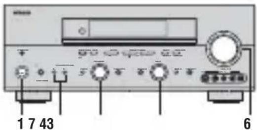
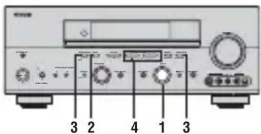
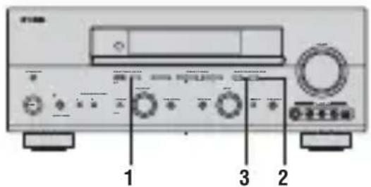
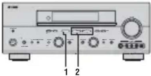
Front panel
1 STANDBY/ON
Turns on this unit or sets it to the standby mode. When you turn on this unit, you will hear a click and there will be a 4 to 5-second delay before this unit can reproduce sound.
Note
In standby mode, this unit consumes a small amount of power in order to receive infrared-signals from the remote control.
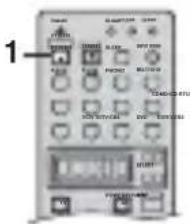
2 OPTIMIZER MIC jack
Use to connect and input audio signals from the supplied microphone for use with the AUTO SETUP function (see page 24).
3 Remote control sensor
Receives signals from the remote control.
4 Front panel display
Shows information about the operational status of this unit.
5 A/B/C/D/E
(RX-V757 only)
Selects one of the 5 preset station groups (A to E) when the unit is in tuner mode.
NEXT
Selects the speaker channel to be adjusted.
6 PRESET/TUNING1/h
(RX-V757 only)
Selects preset station number 1 to 8 when the colon (·) is displayed next to the band indication in the front panel display when the unit is in tuner mode. Selects the tuning frequency when the colon (·) is not displayed.
LEVEL-/+
Adjusts the level of the speaker channel selected using NEXT.
7 MEMORY (MAN'L/AUTO FM) (RX-V757 only)
Stores a station in the memory. Hold down this button for more than 3 seconds to start automatic preset tuning.
8 TUNING MODE (AUTO/MAN'L MONO) (RX-V757 only)
Switches the tuning mode between automatic (AUTO indicator on) and manual (AUTO indicator off).
9VIDEO AUX jacks
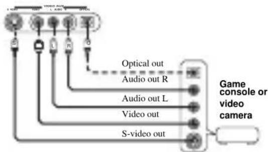
Input audio and video signals from a portable external source such as a game console. To reproduce source signals from these jacks, select V-AUX as the input source.
0 VOLUME
Controls the output level of all audio channels.
This does not affect the REC OUT level.
A PHONES (SILENT CINEMA) jack
Outputs audio signals for private listening with
headphones. When you connect headphones, no signals are output to the PRE OUT jacks or to the speakers.
All Dolby Digital and DTS audio signals are mixed down to the left and right headphone channels.
B SPEAKERS A/B
Turns on or off the set of front speakers connected to the A and/or B terminals on the rear panel each time the corresponding button is pressed.
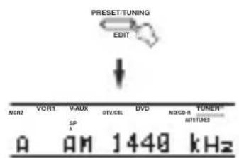
C PRESET/TUNING (EDIT)
(RX-V757 only)
Switches the function of PRESET/TUNING | /h (LEVEL) between selecting preset station numbers and tuning.
D STRAIGHT (EFFECT)
Switches the sound fields off or on. When STRAIGHT is selected, input signals (2-channel or multi-channel) are output directly from their respective speakers without effect processing.
FM/AM
(RX-V757 only)
Switches the reception band when the unit is in tune mode.
F PROGRAM
Use to select sound field programs or adjust the bass/treble balance (in conjunction with TONE CONTROL).
G TONE CONTROL
Use to adjust the bass/treble balance for the front left and right, center, presence and subwoofer channels (see page 31).
INPUT MODE
Sets the priority (AUTO, DTS, ANALOG) for the type of signals received when one component is connected to two or more of this unit's input jacks (see page 37).
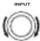
I INPUT selector
Selects the input source you want to listen to or watch.
J MULTI CH INPUT
Selects the source connected to the MULTI CH INPUT
jacks. When selected, the MULTI CH INPUT source takes priority over the source selected with INPUT (or the input selector buttons on the remote control).
K PURE DIRECT
Turns on or off PURE DIRECT mode (see page 35).
ZONE ON/OFF buttons
(RX-V757 only)
MAIN
Switches this unit's operation to control the component in the main room (see page 77).
ZONE 2
Switches this unit's operation to control the component in the second room (Zone 2) (see page 77).
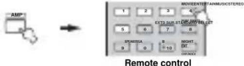
Remote control
This section describes the function of each control on the remote control used to control this unit. To operate other components, see "REMOTE CONTROL FEATURES" on page 68.
1 Infrared window
Outputs infrared control signals. Aim this window at the component you want to operate.
2 TRANSMIT indicator
Flashes while the remote control is sending signals.
3 STANDBY
Sets this unit in the standby mode.
4 SYSTEM POWER
Turns on the power of this unit.
5 Input selector buttons
Select the input source and change the control area.
6 Display window
Shows the name of the selected source component that you can control.
7 LEVEL
Selects the speaker channel to be adjusted and sets the level.
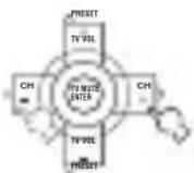
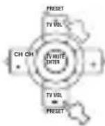
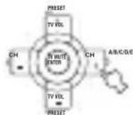
8 Cursor buttons u /d /j /i/ENTER
Use to select and adjust sound field program parameters or SET MENU items.
Press i to select a preset station group (A to E) when the unit is in tuner mode (RX-V757 only).
Press u /d to select a preset station number (1 to 8) when the unit is in tuner mode (RX-V757 only).
9 RETURN
Returns to the previous menu level when adjusting the SET MENU parameters.
0 Sound field program/numeric buttons
Use to select sound field programs.
Use numbers 1 through 8 to select preset stations when the unit is in tune mode (RX-V757 only).
Use SELECT to playback 2-channel sources in surround (see page 34).
Use EXTD SUR. to switch between 5.1 or 6.1/7.1-channel playback of multi-channel software (see page 33).
Use PURE DIRECT to turn on or off PURE DIRECT mode (see page 35).
A SPEAKERS A/B
Use to turn on or off the set of front speakers connected to the A and/or B terminal on the rear panel each time the corresponding button is pressed.
B RE-NAME
Use to change the input source name in the display window (see page 73).
C CLEAR
Use to clear functions acquired when using the learn and rename features, or setting remote control codes (see page 74).
D LEARN
Use to set up manufacturer codes or program functions from other remote controls (see pages 69 and 72).
E SLEEP
Sets the sleep timer.
F INPUT MODE
Sets the priority (AUTO, DTS, ANALOG) for the type of signals received when one component is connected to two or more of this unit's input jacks (see page 37).
G MULTI CH IN
Selects MULTI CH INPUT when using an external decoder (etc.).
H SELECT k/n
Selects another component that you can control independently of the input component selected with the input selector buttons.
I AMP
Selects the AMP mode. You must select the AMP mode to control the main unit.
J VOL+/-
Increases or decreases the volume level.
K MUTE
Mutes the sound. Press again to restore the audio output to the previous volume level.
L SET MENU
Activates the SET MENU function.
M ON SCREEN
Selects the display mode of the on-screen display (OSD) this unit sends to your video monitor.
N STRAIGHT (EFFECT)
Switches the sound fields off or on. When STRAIGHT is selected, input signals (2-channel or multi-channel) are output directly from their respective speakers without effect processing.
O NIGHT
Turns on or off the night listening modes (see page 35).
P Radio Data System tuning buttons (RX-V757 only)
FREQ/TEXT
Press this button when the unit is receiving a Radio Data System station to cycle the display between the PS mode, PTY mode, RT mode, CT mode (if the station offers those Radio Data System data services) and/or the frequency display (see page 45).
PTY SEEK MODE
Press this button to set the unit to the PTY SEEK mode (see page 46).
PTY SEEK START
Press this button to begin searching for a station after the desired program type has been selected in the PTY SEEK mode (see page 46).
EON
Press this button to select a radio program type (NEWS, INFO, AFFAIRS, SPORT) to tune in automatically (see page 47).
Using the remote control
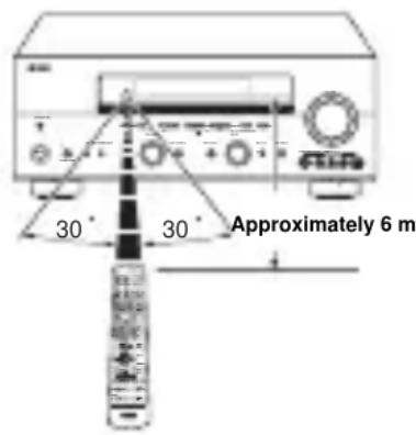
The remote control transmits a directional infrared beam. Be sure to aim the remote control directly at the remote control sensor on the main unit during operation.
■Handling the remote control
- Do not spill water or other liquids on the remote control.
- Do not drop the remote control.
- Do not leave or store the remote control in the following types of conditions:
places of high humidity, such as near a bath
- places of high temperature, such as near a heater or stove
extremely low temperatures
-dustyplaces
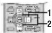
Front panel display
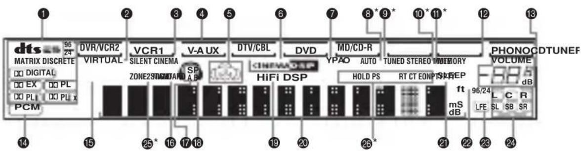
* RX-V757 only
1 Decoder indicators
When any of this unit's decoders function, the respective indicator lights up.
2 VIRTUAL indicator
Lights up when Virtual CINEMA DSP is active (see page 36).
3 SILENT CINEMA indicator
Lights up when headphones are connected and a sound field program is selected (see page 31).
4 Input source indicators
A cursor lights to show the current input source.
5 Sound field indicators
Light to indicate the active DSP sound fields.
Presence DSP sound field
Left surround
DSP sound field

ring position
Right surround
DSP sound field
Surround back DSP sound field
6 CINEMA DSP indicator
Lights up when you select a CINEMA DSP sound field program.
7 YPAO indicator
Lights up during the auto setup procedure and when the auto setup speaker settings are used without any modifications.
8 AUTO indicator (RX-V757 only)
Lights up when this unit is in automatic tuning mode.
9 TUNED indicator (RX-V757 only)
Lights up when this unit is tuned into a station.
STEREO indicator (RX-V757 only)
Lights up when this unit is receiving a strong signal for an FM stereo broadcast while the AUTO indicator is lit.
A MEMORY indicator (RX-V757 only)
Flashes to show that a station can be stored.
B MUTE indicator
Flashes while the MUTE function is on.
C VOLUME level indication
Indicates the current volume level.
D PCM indicator
Lights up when this unit is reproducing PCM (Pulse Code Modulation) digital audio signals.
E STANDARD indicator
Lights up when a decoder is selected (see page 34).
F NIGHT indicator
Lights up when you select night listening mode.
G SP A B indicators
Light up according to the set of front speakers selected. Both indicators light up when both sets of speakers are selected.
Headphones indicator
Lights up when headphones are connected.
I HiFi DSP indicator
Lights up when you select a HiFi DSP sound field program.
J Multi-information display
Shows the current sound field program name and other information when adjusting or changing settings.
K SLEEP indicator
Lights up while the sleep timer is on.
96/24 indicator
Lights up when a DTS 96/24 signal is input to this unit.
M LFE indicator
Lights up when the input signal contains the LFE signal.
N Input channel indicators
Indicate the channel components of the current digital input signal.
O ZONE 2 indicator
(RX-V757 only)
Lights up when Zone 2 power is on.
P Radio Data System indicators
(RX-V757 only)
The name(s) of the Radio Data System data offered by the currently received Radio Data System station light(s) up. EON lights up when an Radio Data System station that offers the EON data service is being received.
PTY HOLD lights up while searching for stations in the PTY SEEK mode.
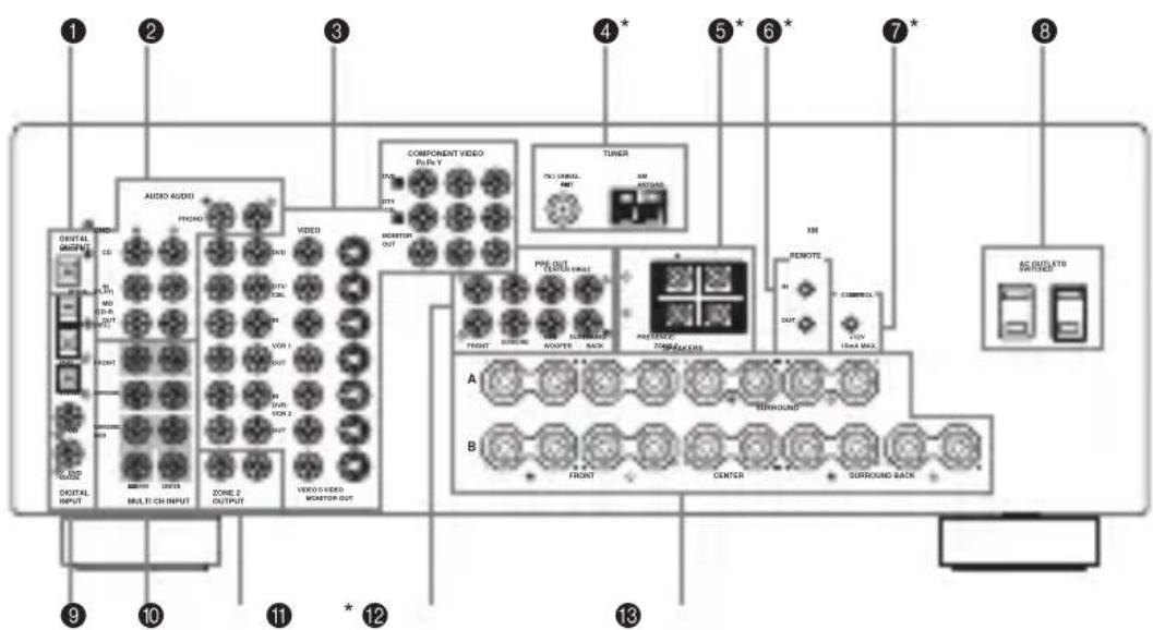
Rear panel
* RX-V757 only (or DSP-AX757SE has different jacks)
1 DIGITAL OUTPUT jacks
See page 19 for details.
2 Audio component jacks
See page 19 for connection information.
3 Video component jacks
See pages 16 and 18 for connection information.
4 Antenna terminals (RX-V757 only)
See page 21 for connection information.
5 PRESENCE/ZONE 2 speaker terminals (RX-V757 only)
PRESENCE speaker terminals (DSP-AX757SE only)
See page 13 for connection information.
6 REMOTE IN/OUT jacks (RX-V757 only)
See page 76 for details.
7 CONTROL OUT jack (RX-V757 only)
This is a control expansion terminal for commercial use.
8 AC OUTLET(S)
Use to supply power to your other A/V components (see page 22).
9 DIGITAL INPUT jacks
See pages 16, 18 and 19 for details.
0 MULTICH INPUTjacks
See page 17 for connection information.
A ZONE 2 OUTPUT jacks (RX-V757 only)
These jacks output analog signals only. See page 76 for details.
TUNER INPUT jacks (DSP-AX757SE only)
These jacks input signals from the external tuner.
B PRE OUT jacks
See page 20 for connection information.
C Speaker terminals
See page 12 for connection information.
SPEAKER SETUP
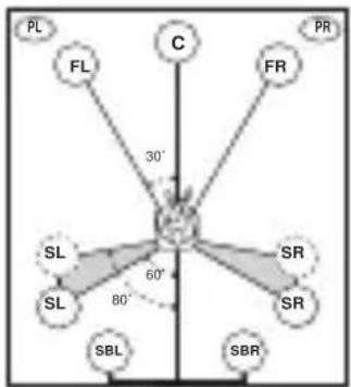
Speaker placement
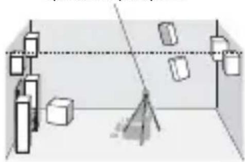
The speaker layout below shows the standard ITU-R* speaker setting. You can use it to enjoy CINEMA DSP and multi-channel audio sources.
- ITU-R is the radio communication sector of the ITU (International Telecommunication Union).
30 cm or more
Front speakers (FR and FL)
The front speakers are used for the main source sound plus effect sounds. Place these speakers an equal distance from the ideal listening position. The distance of each speaker from each side of the video monitor should be the same.
Center speaker (C)
The center speaker is for the center channel sounds (dialog, vocals, etc.). If for some reason it is not practical to use a center speaker, you can do without it. Best results, however, are obtained with the full system. Align the front face of the center speaker with the front face of your video monitor. Place the speaker centrally between the front speakers and as close to the monitor as possible, such as directly over or under it.
Surround speakers (SR and SL)
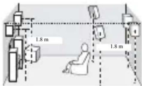
The surround speakers are used for effect and surround sounds. Place these speakers behind your listening position, facing slightly inwards, about 1.8m above the floor.
Surround back speakers (SBR and SBL)
The surround back speakers supplement the surround speakers and provide for more realistic front-to-back transitions. Place these speakers directly behind the listening position and at the same height as the surround speakers. They should be positioned at least 30~cm apart. Ideally, they should be positioned at the same width as the front speakers.
Subwoofer
The use of a subwoofer, such as the YAMAHA Active Servo Processing Subwoofer System, is effective not only for reinforcing bass frequencies from any or all channels, but also for high fidelity reproduction of the LFE (low-frequency effect) channel included in Dolby Digital and DTS software. The position of the subwoofer is not so critical, because low bass sounds are not highly directional. But it is better to place the subwoofer near the front speakers. Turn it slightly toward the center of the room to reduce wall reflections.
Presence speakers (PR and PL)
Presence speakers supplement the sound from the front speakers with extra ambient effects produced by CINEMA DSP (see page 49). These effects include sounds that filmmakers intend to locate a little farther back behind the screen in order to create more theater-like ambience. Place these speakers at the front of the room about 0.5 - 1m outside the front speakers, facing slightly inwards, and about 1.8m above the floor.
Speaker connections
Be sure to connect the left channel (L), right channel (R), "+" (red) and "-(black) properly. If the connections are faulty, no sound will be heard from the speakers, and if the polarity of the speaker connections is incorrect, the sound will be unnatural and lack bass.
CAUTION
- If you will use 4 or 6 ohm speakers, be sure to set this unit's speaker impedance setting to 4 ohms before using (see page 23).
- Before connecting the speakers, make sure that the power of this unit is off.
- Do not let the bare speaker wires touch each other or do not let them touch any metal part of this unit. This could damage this unit and/or speakers.
- Use magnetically shielded speakers. If this type of speakers still creates the interference with the monitor, place the speakers away from the monitor.
A speaker cord is actually a pair of insulated cables running side by side. One cable is colored or shaped differently, perhaps with a stripe, groove or ridges.
Connect the striped (grooved, etc.) cable to the "+" (red) terminals on this unit and your speaker. Connect the plain cable to the "−" (black) terminals.
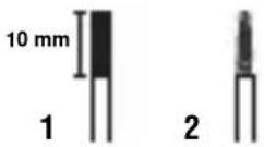
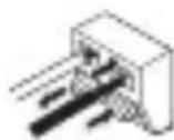
1 Remove approximately 10mm of insulation from the end of each speaker cable.
2 Twist the exposed wires of the cable together to prevent short circuits.
3 Unscrew the knob.
4 Insert one bare wire into the hole in the side of each terminal.
5 Tighten the knob to secure the wire.
Red: positive (+)
Black: negative (-)
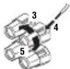
Connecting to PRESENCE/ZONE 2 or PRESENCE speaker terminals
1 Open the tab.
2 Insert one bare wire into the hole of each terminal.
3 Return the tab to secure the wire.
Front speakers (A)
You can connect both surround back and presence speakers to this unit, but they do not output sound simultaneously.
- The surround back speakers output the surround back channel included in Dolby Digital EX and DTS-ES software and only operate when the Dolby Digital EX, DTS-ES or Dolby Pro Logic IIx decoder is turned on.
The presence speakers output ambient effects created by the DSP sound fields. They do not output sound when other sound fields are selected.
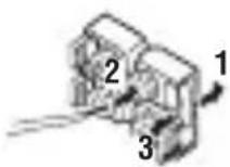
■FRONT terminals
Connect one or two speaker systems (6, 7) to these terminals. If you use only one speaker system, connect it to the FRONT A or B terminals.
CENTER terminals
Connect a center speaker (8) to these terminals.
■SURROUND terminals
Connect surround speakers (4, 5) to these terminals.
SUBWOOFER jack
Connect a subwoofer with built-in amplifier (1), such as the YAMAHA Active Servo Processing Subwoofer System, to this jack.
Connect surround back speakers (9, 10) to these terminals. If you only connect one surround back speaker, connect it to the left (L) terminals.
■PRESENCE terminals
Connect presence speakers (2, 3) to these terminals.
- If you are using RX-V757, you can also use these speakers as Zone 2 speakers (see page 65).
Speaker layout
CONNECTIONS
Before connecting components
CAUTION
Do not connect this unit or other components to the mains power until all connections between components are complete.
Cable indications
For analog signals
left analog cables
right analog cables

For digital signals
optical cables
coaxial cables
For video signals
video cables
S-video cables
component video cables

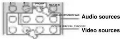
■Analog jacks
You can input analog signals from audio components by connecting audio pin cable to the analog jacks on this unit. Connect red plugs to the right jacks and white plugs to the left jacks.
Digital jacks
This unit has digital jacks for direct transmission of digital signals through either coaxial or fiber optic cables. You can use the digital jacks to input PCM, Dolby Digital and DTS bitstreams. When you connect components to both the COAXIAL and OPTICAL jacks, priority is given to the input signals from the COAXIAL jack. All digital input jacks are compatible with 96-kHz sampling digital signals.
Note
This unit handles digital and analog signals independently. Thus audio signals input to the analog jacks are only output to the analog OUT (REC) jacks. Likewise audio signals input to the digital (OPTICAL or COAXIAL) jacks are only output to the DIGITAL OUTPUT jack.
Dust protection cap
Pull out the cap from the optical jack before you connect the fiber optic cable. Do not discard the cap. When you are not using the optical jack, be sure to put the cap back in place. This cap protects the jack from dust.

Video jacks
This unit has three types of video jacks. Connection depends on the availability of input jacks on your monitor. The signals input through the SVIDEO jacks on this unit are automatically converted for output through theVIDEO jacks. WhenVIDEO CONV.is set to ON (see page 64), signals input through theVIDEO jacks can be output through the SVIDEO and COMPONENTVIDEO jacks. Likewise, signals input through the SVIDEO jacks can also be output through the COMPONENTVIDEO jacks.


VIDEO jacks
For conventional composite video signals.
SVIDEOjacks
For S-video signals, separated into luminance (Y) and color (C) video signals to achieve high-quality color reproduction.
COMPONENTVIDEOjacks
For component signals, separated into luminance (Y) and color difference (P_B,P_R) to provide the best quality in picture reproduction.
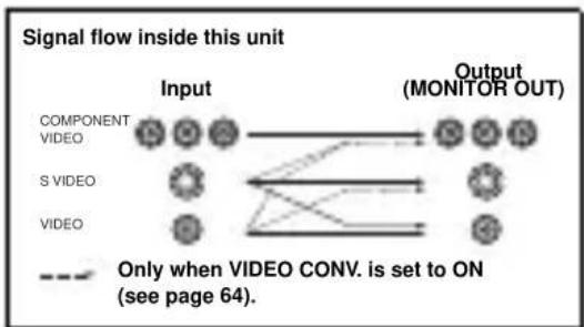
Note
When signals are input through both the SVIDEO andVIDEO jacks, signals input through the SVIDEO jack have priority.
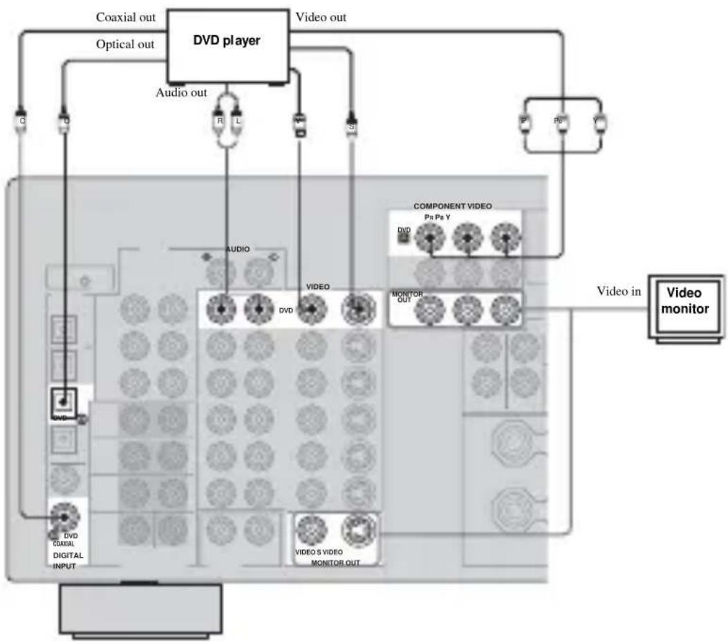
Connecting video components
Connections for DVD playback
Note
Be sure to connect your video source components in the same way you connect your video monitor to this unit ifVIDEO CONV. (see page 64) is set to OFF. For example, if you connect your video monitor to this unit using aVIDEO connection, connect your video source components to this unit using theVIDEO connections. (Even whenVIDEO CONV. is set to OFF, S-video signals input from your video source component are automatically converted to composite signals in this unit.)
Connecting to the MULTICH INPUTjacks
This unit is equipped with 8 additional input jacks (left and right FRONT, CENTER, left and right SURROUND, left and right SURROUND BACK and SUBWOOFER) for discrete multi-channel input from a multi-format player, external decoder, sound processor or pre-amplifier.
Connect the output jacks on your multi-format player or external decoder to the MULTI CH INPUT jacks. Be sure to match the left and right outputs to the left and right input jacks for the front and surround channels.
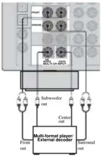
For 6-channel input
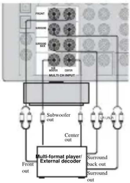
For 8-channel input
Notes
- When you select MULTI CH INPUT as the input source, this unit automatically turns off the digital sound field processor, and you cannot select sound field programs.
- This unit does not redirect signals input to the MULTI CH INPUT jacks to accommodate for missing speakers. We recommend that you connect at least a 5.1-channel speaker system before using this feature.
- When headphones are used, only front left and right channels are output.
Connections for other video components
Notes
- Be sure to connect your video source components in the same way you connect your video monitor to this unit ifVIDEO CONV. (see page 64) is set to OFF. For example, if you connect your video monitor to this unit using aVIDEO connection, connect your video source components to this unit using theVIDEO connections.
- Converted video signals are only output to MONITOR OUT jacks. When recording, you must make the same type of video connections (i.e., S-video) between each component.

VIDEO AUX jacks (on the front panel)
Use these jacks to connect any video source, such as a game console or video camera, to this unit.
Connecting audio components
Connections for audio components
Connecting a turntable
PHONO jacks are for connecting a turntable with an MM or high-output MC cartridge. If you have a turntable with a low-output MC cartridge, use an in-line boosting transformer or MC-head amplifier when connecting to these jacks.
Connect your turntable to the GND terminal to reduce noise in the signal. However you may hear less noise without the connection to the GND terminal for some record players.
Connecting to an external amplifier
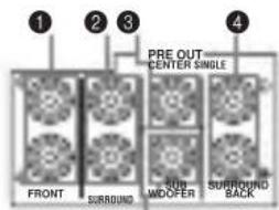
If you want to increase the power output to the speakers, or want to use another amplifier, connect an external amplifier to the PRE OUT jacks as follows.
Notes
- When audio pin plugs are connected to the PRE OUT jacks for output to an external amplifier, do not make connections to the corresponding SPEAKERS terminals. Set the volume of the amplifier connected to this unit to the maximum.
- The signals output through the FRONT PRE OUT and CENTER PRE OUT jacks are affected by the TONE CONTROL settings.
- If SPEAKERS A is turned off and SP B is set to ZONE B (see page 65), signals will only be output from the FRONT PRE OUT jacks.
5
1 FRONT PRE OUT jacks
Front channel line output jacks.
2 SURROUND PRE OUT jacks
Surround channel line output jacks.
3 CENTER PRE OUT jack
Center channel line output jack.
4 SURROUND BACK PRE OUT jacks
Surround back or presence channel line output jacks.
5 SUBWOOFER PRE OUT jack
Connect a subwoofer with built-in amplifier, such as the YAMAHA Active Servo Processing Subwoofer System, to this jack.
Notes
Each PRE OUT jack outputs the same channel signals as the corresponding speaker terminals.
- Adjust the volume level of the subwoofer with the control on the subwoofer. It is also possible to adjust the volume level using the remote control (see "Manually adjusting speaker levels" on page 53).
- Some signals may not be output from the SUBWOOFER PRE OUT jack depending on the SPEAKER SET (see page 57) and LFE/BASS OUT (see page 58) settings.
Connecting the FM and AM antennas (RX-V757 only)
Both FM and AM indoor antennas are included with this unit. In general, these antennas should provide sufficient signal strength. Connect each antenna correctly to the designated terminals.
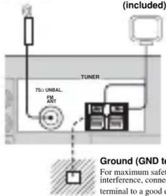
Indoor FM antenna (included)
Ground (GND terminal)
For maximum safety and minimum interference, connect the antenna GND terminal to a good earth ground. A good earth ground is a metal stake driven into moist earth.
Connecting the AM loop antenna
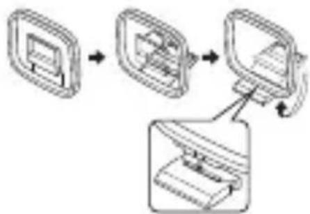
1 Set up the AM loop antenna.
2 Press and hold the tab to insert the AM loop antenna lead wires into the AM ANT and GND terminals.
3 Orient the AM loop antenna for the best reception.

Notes
- The AM loop antenna should be placed away from this unit.
- The AM loop antenna should always be connected, even if an outdoor AM antenna is connected to this unit.
- A properly installed outdoor antenna provides clearer reception than an indoor one. If you experience poor reception quality, an outdoor antenna may improve the quality. Consult the nearest authorized YAMAHA dealer or service center about outdoor antennas.
Connecting the power supply cord
Connecting the AC power cord
Plug the power cord into an AC wall outlet.
AC OUTLET(S) (SWITCHED)
DSP-AX757SE 1 outlet RX-V757 2 outlets
Use these outlets to connect the power cords from your other components to this unit. Power to the AC OUTLET(S) is controlled by this unit's STANDBY/ON (or SYSTEM POWER and STANDBY). The outlet(s) supply power to any connected component whenever this unit is turned on. For information on the maximum power (total power consumption of components), see "SPECIFICATIONS" on page 95.
Memory back-up
The memory back-up circuit prevents the stored data from being lost even if this unit is in the standby mode. However if the power cord is disconnected from the AC wall outlet, or the power supply is cut for more than one week, the stored data will be lost.
Speaker impedance setting
CAUTION
If you are using 4 or 6 ohm speakers, set the impedance to 4 or 6 ohms as follows before turning on the power.
Be sure this unit is in the standby mode.
1 Turn off the power to this unit, and while holding down STRAIGHT (EFFECT), press STANDBY/ON.
This unit turns on, and "SP IMP." appears in the front panel display.


While holding down, press

SP IMP.
2 Press STRAIGHT (EFFECT) repeatedly to select "4Ω MIN".


3 Press STANDBY/ON to turn off the power.

The setting you made is reflected the next time this unit's power is turned on.
Turning on the power
When all connections are complete, turn on the power of this unit.

1 Press STANDBY/ON (or SYSTEM POWER on the remote control) to turn on the power of this unit.

Front panel

or
Remote control
2 Turn on the video monitor connected to this unit.
AUTO SETUP
Introduction
This receiver employs YAMAHA Parametric Room Acoustic Optimizer (YPAO) technology which lets you avoid troublesome listening-based speaker setup and achieves highly accurate sound adjustments. The supplied optimizer microphone collects and analyzes the sound your speakers produce in your actual listening environment.
Notes
- Please be advised that it is normal for loud test tones to be output during the auto setup procedure.
- If auto setup stops and error messages appear on the screen, follow the troubleshooting on page 28.
YPAO performs the following checks and makes appropriate adjustments to give you the best possible sound from your system.
WIRING:
Checks which speakers are connected and the polarity of each speaker.
SIZE:
Checks the speakers frequency response and sets the crossover/high cut frequency for the subwoofer to improve the sound relationship between the speakers and the subwoofer.
DISTANCE:
Checks the distance of each speaker from the listening position and adjusts the delay of each channel so that the sound from each speaker reaches the listening position at the same time. Also checks the phase of each speaker.
EQUALIZING:
Adjusts frequency and levels of each channel's parametric equalizer to reduce coloration across the channels and create a cohesive sound field. This is particularly important if you use different brands or sizes of speakers for some channels or have a room with unique sonic characteristics.
YPAO equalizing calibration incorporates three parameters (frequency, level and Q factor) for each of the seven bands in its parametric equalizer to provide highly precise automatic adjustment of frequency characteristics.
LEVEL:
Checks and adjusts the sound level (volume) of each speaker.
Optimizer microphone setup
1 Connect the supplied optimizer microphone to the OPTIMIZER MIC jack on the front panel.
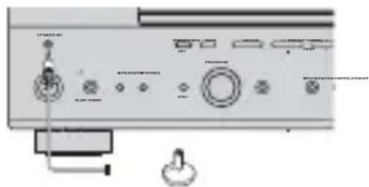
Notes
After you have completed the auto setup procedure, be sure to disconnect the optimizer microphone.
- The optimizer microphone is sensitive to heat.
- Keep it away from direct sunlight.
- Do not place it on top of this unit.
2 Place the optimizer microphone on a flat level surface with the omni-directional microphone head upward, at your normal listening position.
If possible, use a tripod (etc.) to affix the optimizer mic at the same height as your ears would be when you are seated in your listening position.
Optimizer microphone position
Starting the setup
For best results, make sure the room is as quiet as possible during the auto setup procedure (YPAO). If there is too much ambient noise, the results may not be satisfactory.
y
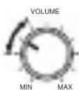
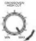
If your subwoofer has adjustable volume and crossover/high cut frequency controls, set the volume between 9 and 11 o'clock (as viewed on a conventional clockface) and set the crossover/high cut frequency to the maximum.
Subwoofer
1 Switch on this unit and your video monitor.
Make sure the OSD is displayed.
2 Press AMP.

3 Press SET MENU.

y When MEMORY GUARD is set to ON, you cannot select any other SET MENU items (see page 60).
4 Press u /d to select AUTO SETUP, then press ENTER.
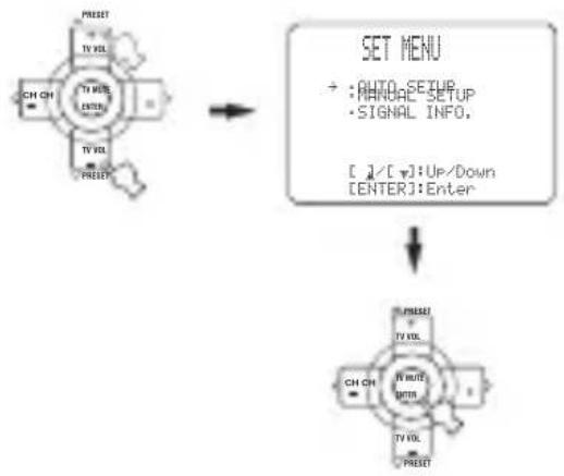
5 Press u /d to select SETUP, then press j /i to select the desired setting.
1 AUTO: MENU
SETUP· AUTO START Automatic Processing of top down [C1/C1]:Select
AUTO To perform the auto setup procedure (YPAO).
RELOAD To reload the last auto setup (YPAO) settings to override any manual changes.
UNDO To undo the last auto setup (YPAO) and restore the previous settings.
DEFAULT To restore the factory preset (default) setup parameters.
Y You can choose RELOAD or UNDO only if you have already performed the auto setup procedure.
6 Press to select "START", then press ENTER to start the setup procedure.
The screen changes as follows.
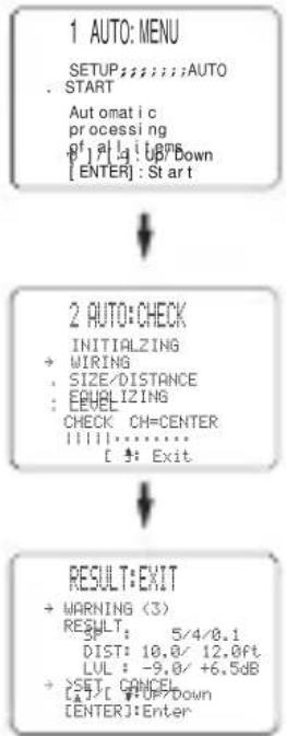
The results displayed in the RESULT:EXIT screen are as follows:
SP The number of connected speakers
displayed in the order: Front/Back/Subwoofer
DI ST The distance of the speakers from this unit displayed in the order:
Closest speaker distance/Farthest speaker distance
LVL The speaker output level displayed in
the order:
Lowest output level/Highest output
level
If you selected AUTO in step 5, "WAITING"
appears when the auto setup procedure is started,
then loud test tones are output from each speaker in turn.
-
If you selected DEFAULT, RELOAD or UNDO in step 5, no test tones are output.
-
If an ERROR screen appears, see "If an error screen appears" on page 26.
If a warning screen appears, see "If a warning
screen appears" on page 27.
y
You can display the detailed result information by using d and
- ENTER to select "RESULT". In the detailed result information,
screen, you can switch information by pressing u /d /j /i.
7
Press j / i to select SET or CANCEL, then
press ENTER to return to the SET MENU
screen.
RESULT:EXIT
WARNING(3)
RESULT
BST158120.0f 1111-9.0+5.08
SET CANCEL
EAT
SET To apply the auto setup (YPAO)
settings.
CANCEL To cancel the auto setup (YPAO)
without making any changes.
y
If you are not satisfied with the result or want to manually adjust
each setup parameter, use the manual setup parameters (see page
52)
Notes
- If E-10 appears during testing, restart the procedure from step 3.
To cancel the auto setup procedure before completion, press u.
If an error screen appears
Use u /d /j /i to select RETRY or EXIT, then press
ENTER.
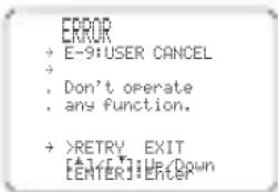
RETRY To retry the auto setup procedure.
EXITo exit auto setup.
■If a warning screen appears
1 Press ENTER to display detailed information about the warning.
Press j / i to switch between warning messages.
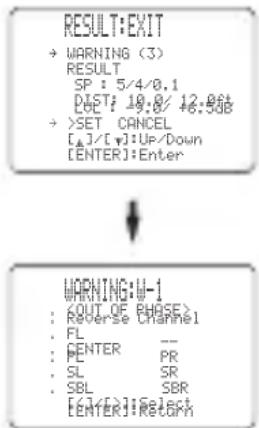
W-1 example screen
For details about each message, see page 29.
y Warnings let you know about potential problems detected during auto setup. Warnings will not cancel the auto setup.
- The number of warnings is displayed to the right of "WARNING".
- When the warning is not applicable to a speaker, "--" is displayed.
2 When you are finished, press ENTER to return to the RESULT:EXIT screen.
Continue from step 7 on page 26.
Notes
- If you change speakers, speaker positions, or the layout of your listening environment, perform auto setup again to re-calibrate your system.
- Depending on listening environments, SWFR PHASE:REV appears in AUTO:CHECK and SUBWOOFER PHASE parameter in SET MENU (see page 59) is automatically set to REVERSE. To select the desired setting, change the SUBWOOFER PHASE parameter in SET MENU.
- In the DISTANCE results, the distance displayed may be longer than the actual distance depending on the characteristics of your subwoofer.
Troubleshooting for auto setup procedure
Before auto setup
| Error message Cause | Remedy | |
| Connect MIC | Optimizer microphone is not connected. • Connect the supplied optimizer microphone to the OPTIMIZER MIC jack on the front panel. | |
| Unplug HP | Headphones are connected. • Unplug the headphones. | |
Errors during auto setup
| Error message Cause | Remedy | |
| E-1: NO FRONT SP | Front L/R channel signal(s) is (are) not detected. | • Select the front speakers with SPEAKERS A/B. • Check the front left and right speaker connections. • Turn on the power to the external amplifier (when the front speaker signals are output from an external amplifier). |
| E-2: NO SURR. SP | Only one surround channel signal is detected. • Check the surround speaker connections. | |
| E-3: NO PRES. SP | Only one presence channel signal is detected. • Check the presence speaker connections. | |
| E-4: SBR->SBL | Only right surround back channel signal is detected. | • Connect the surround back speaker to the LEFT SURROUND BACK SPEAKERS terminal if you only have one surround back speaker. |
| E-5: NOI SY | Background noise is too loud. • Try the auto setup | procedure in a quiet environment. • Turn off noisy electric equipment like air conditioners (etc.) or move them away from the optimizer microphone. |
| E-6: CHECK SUR. | Surround back speaker(s) is (are) connected, though surround L/R speakers are not. | • Connect surround speakers when you use (a) surround back speaker(s). • Check the surround speaker connections. |
| E-7: NO MIC | The optimizer microphone was unplugged during the auto setup procedure. | • Do not touch the optimizer microphone during the auto setup procedure. |
| E-8: NO SIGNAL | The optimizer microphone does not detect test tones. | • Check the microphone setting. • Check the speaker connections and placement. |
| E-9: USER CANCEL | The auto setup procedure was cancelled due to user activity. | • Perform the auto setup procedure again. Do not adjust VOLUME (etc.) during the auto setup procedure. |
| E-10: INTERNAL ERROR | A DSP communication error or hangup occurred. | • Perform the auto setup procedure again. |
Warnings after auto setup
Press j /i to display detailed information about individual warnings.
| Warning message Cause | Remedy | |
| W-1: OUT OF PHASE | Speaker polarity is not correct. This message may appear depending on the speakers even when the speakers are connected correctly. | Check the speaker connections for proper polarity(+/-). |
| W-2: OVER 24m | The distance between the speaker and the listening position is 24 m or more. | Move the speaker closer to the listening position. Check the speaker connections for proper polarity(+/-). |
| W-3: LEVEL ERROR | The difference of volume level among speakers is excessive. (No level correction is made.) | Readjust the speaker installation so that all speakers are set in locations with similar conditions. Check the speaker connections for proper polarity(+/-). Use speakers of similar quality and efficiency. |
- If the ERROR or WARNING screens appears, check the cause of the problem, then perform the auto setup procedure again.
- If warning W-1 appears, corrections are made, but they may not be optimal.
- If warning W-2 or W-3 appears, no corrections are made.
- If error E-10 occurs repeatedly, please contact a qualified YAMAHA service center.
PLAYBACK
Basic operations
1 Press STANDBY/ON (or SYSTEM POWER on the remote control) to turn on the power.

Front panel

or
Remote control
2 Turn on the video monitor connected to this unit.
3 Press SPEAKERS A or B (or press AMP to select the AMP mode, then press SPEAKERS A or B on the remote control).
Each press turns the respective speakers on or off.

Front panel
or
Remote control
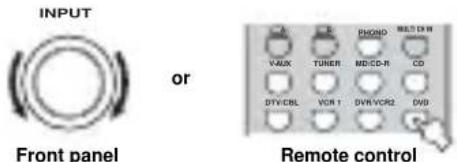
4 Select the input source.
Rotate INPUT (or press one of the input selector buttons on the remote control) to select the input you desire.
Front panel
or
Remote control
The current input source name and input mode appear in the front panel display and video monitor for a few seconds.
5 Start playback or select a broadcast station on the source component.
Refer to the operating instructions for the component.
6 Adjust the volume to the desired output level.
Front panel
or
Remote control
7 Select a sound field program if desired.
Use PROGRAM (or press AMP to select the AMP mode, then press one of the sound field program buttons) to select a sound field program. See page 49 for details about sound field programs.

PROGRAM
Front panel
or
■To listen with headphones ("SILENT CINEMA")
"SILENT CINEMA" allows you to enjoy multi-channel music or movie sound, including Dolby Digital and DTS surround, through ordinary headphones. "SILENT CINEMA" activates automatically whenever you connect headphones to the PHONES jack while listening to CINEMA DSP or HiFi DSP sound field programs. When activated, the "SILENT CINEMA" indicator lights up in the front panel display.
Notes
- This unit will not be set to "SILENT CINEMA" when MULTI CH INPUT is selected as the input source.
-SILENT CINEMA" is not effective when PURE DIRECT or the 2ch Stereo program is selected, or in STRAIGHT mode.
To adjust the tone
You can adjust the tonal quality of your front left and right, center, and subwoofer speakers or headphones (when connected). Press TONE CONTROL on the front panel repeatedly to select TREBLE or BASS, then rotate PROGRAM to the right or left to increase or decrease.
- Select TREBLE to adjust the high frequency response.
- Select BASS to adjust the low frequency response.


PROGRAM
Speaker and headphone adjustments are stored independently.
Notes
TONE CONTROL is not effective during playback in the PURE DIRECT mode, or when MULTI CH INPUT is selected (page 35).
- When TONE BYPASS is set to "AUTO" (page 61), and BASS and TREBLE are set to 0dB audio output automatically bypasses this unit's tone control circuitry.
■To mute the sound
Press MUTE on the remote control. The MUTE indicator flashes in the front panel display.
To resume the audio output, press MUTE again (or press VOL - / +
The MUTE indicator disappears from the display.
y
You can adjust the muting level (see page 61).

■Selecting MULTI CH INPUT
Press MULTI CH INPUT (or MULTI CH IN on the remote control) so that "MULTI CH INPUT" appears in the front panel display and video monitor.
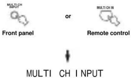
Note
When "MULTI CH INPUT" is shown in the front panel display, no other source can be played. To select another input source with INPUT (or one of the input selector buttons), press MULTI CH INPUT (or MULTI CH IN on the remote control) to turn off "MULTI CH INPUT" in the front panel display.
Playing video sources in the background
You can combine a video image from a video source with sound from an audio source. For example, you can enjoy listening to classical music while viewing beautiful scenery from the video source on the video monitor.
Use the input selector buttons on the remote control to select a video source, then select an audio source.
Note
If you want to enjoy audio from the MULTI CH INPUT jacks together with a video source, first select the video source, then press MULTI CH INPUT (or MULTI CH IN on the remote control).
Selecting sound field programs
■Front panel operation
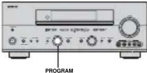
Rotate PROGRAM to select the desired program.
The name of the selected program appears in the front panel display and video monitor.
Remote control operation
Press AMP to select the AMP mode, then press one of the sound field program buttons to select the desired program.
The name of the selected program appears in the front panel display.
y
Choose a sound field program based on your listening preference, and not on the name of the program.
Notes
- When you select an input source, this unit automatically selects the last sound field program used with that source.
Sound field programs cannot be selected when MULTI CH INPUT is selected. - Sampling frequencies higher than 48kHz (except for DTS 96/24 signals) will be sampled down to 48kHz , then sound field programs will be applied.
Enjoying multi-channel software
If you connected a surround back speaker, use this feature to enjoy 6.1/7.1-channel playback for multi-channel sources using the Dolby Pro Logic IIx, Dolby Digital EX or DTS-ES decoders.
Press AMP to select the AMP mode, then press EXTD SUR. on the remote control to switch between 5.1 and 6.1/7.1-channel playback.

To select a decoder, press j / i repeatedly when PLIIxMusic (etc.) is displayed.
Auto (AUTO)
When a signal (flag) that can be recognized by the unit is input, the unit selects the optimum decoder for playing back the signal in 6.1/7.1 channels.
If the unit cannot recognize the flag or no flag is present in the input signal, it cannot automatically be played in 6.1/7.1 channels.
Decoders (select with j /i)
You can select from the following decoders depending on the format of the software you are playing.
PLI | xMovi e
For playing back Dolby Digital or DTS signals in 6.1/7.1 channels using the Pro Logic IIx movie decoder. PLI xMus i c
For playing back Dolby Digital or DTS signals in 6.1/7.1 channels using the Pro Logic IIx music decoder.
EX/ES
For playing back Dolby Digital signals in 6.1/7.1 channels using the Dolby Digital EX decoder.
DTS signals are played back in 6.1/7.1 channels using the DTS-ES decoder. EX
For playing back Dolby Digital or DTS signals in 6.1/7.1 channels using the Dolby Digital EX decoder.
Off (OFF)
Decoders are not used to create 6.1/7.1 channels.
When "SUR. B L/R SP" is set to SMLx1 or LRGx1 (see
page 58), the surround back channel will be output from the left SURROUND BACK speaker terminals.
Notes
- Some 6.1-channel compatible discs do not have a signal (flag) which this unit can automatically detect. When playing these kinds of discs with 6.1-channel, select a decoder (PLIIx Movie, PLIIx Music, EX/ES or EX) manually.
-
6.1-channel playback is not possible even if EXTD SUR. is pressed in the following cases:
-
When "SUR. L/R SP" (see page 57) or "SUR. B L/R SP" (see page 58) is set to NONE.
- When the source connected to the MULTI CH INPUT jack is being played.
- When the source being played does not contain surround left and right channel signals.
- When a Dolby Digital KARAOKE source is being played.
-
When "2ch Stereo" or PURE DIRECT is selected.
-
When the power of this unit is turned off, this setting will be reset to AUTO.
- The Pro Logic IIx decoder is not available when "SUR. B L/R SP" is set to NONE (see page 58).
- PLIIxMovie cannot be selected when "SUR. B L/R SP" is set to SMLx1 or LRGx1 (see page 58).
■Enjoying 2-channel software in surround
Signals input from 2-channel sources can also be played back on multiple channels.
Press AMP to select the AMP mode, then press STANDARD on the remote control to switch between the SUR. STANDARD and SUR. ENHANCED programs.

Or press MOVIE to select the MOVIE THEATER program.

Press SELECT on the remote control to select the decoder.

You can select from the following modes depending on the type of software you are playing and your personal preference.
When you select the SUR. STANDARD program:
PRO LOGIC
Dolby Pro Logic processing for any sources.
PLI Movie
Dolby Pro Logic II processing for movie software.
PLIIMusic
Dolby Pro Logic II processing for music software.
PLI Game
Dolby Pro Logic II processing for game software.
PLI X Movie
Dolby Pro Logic IIx processing for movie software.
PLI x Music
Dolby Pro Logic IIx processing for music software.
PLI x Game
Dolby Pro Logic IIx processing for game software.
Neo: 6 Cinema
DTS processing for movie software.
Neo:6 Music
DTS processing for music software.
When you select the SUR. ENHANCED or MOVIE THEATER program:
PRO LOGIC
Dolby Pro Logic processing for any sources.
PLI Movie
Dolby Pro Logic II processing for movie software.
PLI X Movie
Dolby Pro Logic IIx processing for movie software.
Neo: 6 Cinema
DTS processing for movie software.
y
You can also select a decoder by pressing j / i on the remote control when the decoder type is displayed in the short message display.
Note
The Pro Logic IIx decoder is not available when "SUR. B L/R SP" is set to NONE (see page 59).
■Listening to high fidelity stereo sound (PURE DIRECT)
PURE DIRECT allows you to bypass this unit's decoders and DSP processors, and turn off the video circuitry and front panel display to enjoy pure high fidelity sound from analog and PCM sources.
Press PURE DIRECT (or press AMP to select the AMP mode, then press PURE DIRECT on the remote control) to activate pure direct.
The indicator around the front panel button lights up.

Front panel Remote control
Y The front panel display switches on momentarily when an operation is performed.
To cancel, press PURE DIRECT again.
The indicator around the front panel button goes out and the previous settings are restored.
Notes
- To avoid unexpected noise, do not play DTS-encoded CDs in this mode.
- When a multi-channel signal (Dolby Digital or DTS) is input, this unit automatically switches to the corresponding analog input.
- No sound will be output from the subwoofer.
The following operations are not possible during PURE
DIRECT operation:
- switching the sound field program
- displaying the OSD
adjusting SET MENU parameters
all video functions (video conversion etc.) - PURE DIRECT is automatically cancelled whenever this unit is set to the standby mode.
Night listening modes
The night listening modes are designed to improve listenability at lower volumes or at night. Choose either NIGHT:CINEMA or NIGHT:MUSIC depending on the type of material you are playing.
Press AMP to select the AMP mode, then press NIGHT repeatedly on the remote control to select cinema or music.
When night listening is selected, the NIGHT indicator in the front panel display lights up.

- Select NIGHT:CINEMA when watching films to reduce the dynamic range of film soundtracks and make dialog easier to hear at lower volumes.
- Select NIGHT:MUSIC when listening to music sources to preserve ease-of-listening for all sounds.
- Select OFF if you do not want to use this function.
Press j /i to adjust the effect level while NIGHT:CINEMA or NIGHT:MUSIC is displayed.
This adjusts the level of compression.
Remote control
Effect.LvI:MID
- Select MIN for minimum compression.
- Select MID for standard compression.
- Select MAX for maximum compression.
Y NIGHT:CINEMA and NIGHT:MUSIC adjustments are stored independently.
Notes
- You cannot use the night listening modes with PURE DIRECT or MULTI CH INPUT.
The night listening modes may vary in effectiveness depending on the input source and surround sound settings you use.
Downmixing to 2 channels
You can enjoy 2-channel stereo playback even from multi-channel sources.
Rotate PROGRAM (or press AMP to select the AMP mode, then press STEREO on the remote control) to select 2ch Stereo.

PROGRAM
or

Remote control

Front panel
2ch Stereo
Y You can use a subwoofer with this program when SWFR or BOTH is selected in "BASS OUT".
■Listening to unprocessed input signals
In STRAIGHT mode, two channel stereo sources are output from only the front left and right speakers. Multi-channel sources are decoded straight into the appropriate channels without any additional effect processing.
Press STRAIGHT to select STRAIGHT.

STRAIGHT
Front panel
or

STRAIGHT
Remote control

STRAI GHT
Press STRAIGHT (EFFECT) again so that "STRAIGHT" disappears from the display when you want to turn the sound effect back on.
■Virtual CINEMA DSP
Virtual CINEMA DSP allows you to enjoy the CINEMA DSP programs without surround speakers. It creates virtual speakers to reproduce the natural sound field. If you set "SUR. L/R SP" to NONE (see page 57), Virtual CINEMA DSP activates automatically whenever you select a CINEMA DSP sound field program.
Note
Virtual CINEMA DSP will not activate, even when "SUR. L/R
SP" is set to NONE (see page 57) in the following cases:
-
When MULTI CH INPUT is selected as the input source.
-
When headphones are connected to the PHONES jack.
Selecting input modes
This unit comes with a variety of input jacks. Do the following to select the type of input signals you want to use.
1 Rotate INPUT (or press one of the input selector buttons on the remote control) to select the input source.
2 Press INPUT MODE to select an input mode.
In most cases, use AUTO.
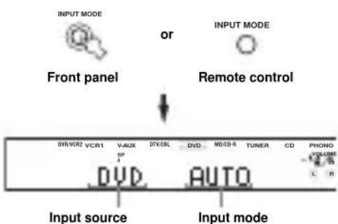
AUTO Automatically selects input signals in the following order:
1) Digital signals*
2) Analog signals
DTS Selects only digital signals encoded in DTS. If no DTS signals are input, no sound is output.
ANALOG Selects only analog signals. If no analog signals are input, no sound is output.
- If this unit detects a Dolby Digital or DTS signal, the decoder automatically switches to the appropriate decoder.

You can adjust the default input mode of this unit (see page 63).
Notes
- When playing a DTS-CD/LD, be sure to set the INPUT MODE to DTS.
- If the digital output data of the player has been processed in any way, you may not be able to perform DTS decoding even if you make a digital connection between this unit and the player depending on the player.
Displaying information about the input source
You can display the type, format and sampling frequency of the current input signal.
1 Select the input source.

2 Press STRAIGHT.

3 Press u / d to display the following information about the input signal.
(Format) Signal format display. When the unit
cannot detect a digital signal it automatically switches to analog input.
i n Number of source channels in the input
signal. For example, a multi-channel
soundtrack with 3 front channels, 2
surround channels and LFE, is
displayed as "3/2/LFE".
f S Sampling frequency. When the unit is
unable to detect the sampling
frequency "Unknown" appears.
r at e Bit rate. When the unit is unable to
detect the bit rate "Unknown" appears.
flg Flag data encoded with DTS or Dolby
Digital signals that cue this unit to
automatically switch decoders.
FM/AM TUNING (RX-V757 ONLY)
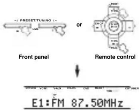
Automatic and manual tuning
There are 2 tuning methods; automatic and manual. Automatic tuning is effective when station signals are strong and there is no interference.
Automatic tuning
1 Rotate INPUT to select TUNER as the input source.

2 Press FM/AM to select the reception band. "FM" or "AM" appears in the front panel display.
3 Press TUNING MODE (AUTO/MAN'L MONO) so that the AUTO indicator lights up in the front panel display.

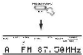
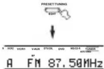
If a colon (·) appears in the front panel display, tuning is not possible. Press PRESET/TUNING (EDIT) to turn the colon (·) off.
4 Press PRESET/TUNING /h once to begin automatic tuning.
Press h to tune into a higher frequency, or press I to tune into a lower frequency.
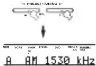
When tuned into a station, the TUNED indicator lights up and the frequency of the received station is shown in the front panel display.
Manual tuning
If the signal from the station you want to select is weak, tune into it manually. Manually tuning into an FM station will automatically switch the tuner to monaural reception to increase the signal quality.
1 Select TUNER and the reception band following steps 1 and 2 as described in "Automatic tuning".
2 Press TUNING MODE (AUTO/MAN'L MONO) so that the AUTO indicator disappears from the front panel display.


AUTO Disappears
If a colon (·) appears in the front panel display, tuning is not possible. Press PRESET/TUNING (EDIT) to turn the colon (·) off.
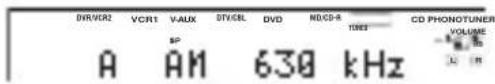
3 Press PRESET/TUNING1/h to tune into the desired station manually.
Hold down the button to continue searching.

Presetting stations
Automatically presetting FM stations
You can use the automatic preset tuning feature to store FM stations. This function enables this unit to automatically tune into FM stations with strong signals, and to store up to 40 (8 stations in 5 groups, A1 through E8) of those stations in order. You can then recall any preset station easily by selecting the preset station number.
Press FM/AM to select the FM band.


FM
2 Press TUNING MODE (AUTO/MAN'L MONO) so that the AUTO indicator lights up in the front panel display.


AUTO Lights up
If a colon (·) appears in the front panel display, tuning is not possible. Press PRESET/TUNING (EDIT) to turn the colon (·) off.
3 Press and hold MEMORY (MAN'L/AUTO FM) for more than 3 seconds.
The preset number, the MEMORY and AUTO indicators flash. After about 5 seconds, automatic presetting starts from the frequency currently displayed and proceeds toward the higher frequencies.
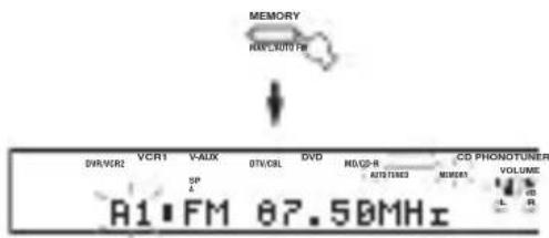
When automatic preset tuning is completed, the front panel display shows the frequency of the last preset station.
Notes
- Any stored station data existing under a preset number is cleared when you store a new station under that preset number.
- If the number of received stations does not reach 40 (E8), automatic preset tuning has automatically stopped after searching all stations.
- Only FM stations with sufficient signal strength are stored automatically by automatic preset tuning. If the station you want to store is weak in signal strength, tune into it manually, and store it by following the procedure in "Manually preseting stations".
Automatic preset tuning options:
You can select the preset number from which this unit will store FM stations and/or begin tuning toward lower frequencies.
After pressing MEMORY in step 3:
1 Press A/B/C/D/E, then PRESET/TUNING | /h to select the preset number under which the first station will be stored. Automatic preset tuning will stop when stations have all been stored up to E8.
2 Press PRESET/TUNING (EDIT) to turn off the colon (: and then press PRESET/TUNING I to begin tuning toward the lower frequencies.
Memory back-up
The memory back-up circuit prevents the stored data from being lost even if this unit is set in the standby mode, the power cord is disconnected from the AC outlet, or the power supply is temporarily cut due to power failure. However, if the power is cut for more than one week, the preset stations may be cleared. If so, store the stations again by using the preset station methods.
Manually presetting stations
You can also store up to 40 stations (8 stations in 5 groups, A1 through E8) manually.

1 Tune into a station.
See page 39 for tuning instructions.
When tuned into a station, the front panel display shows the frequency of the station received.
2 Press MEMORY (MAN'L/AUTO FM).
The MEMORY indicator flashes for about 5 seconds.

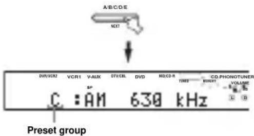
3 Press A/B/C/D/E (NEXT) repeatedly to select a preset station group (A to E) while the MEMORY indicator is flashing.
The group letter appears. Check that the colon () appears in the front panel display.
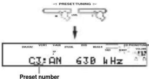
4 Press PRESET/TUNING /h to select a preset station number (1 to 8) while the MEMORY indicator is flashing.
Press h to select a higher preset station number. Press I to select a lower preset station number.
5 Press MEMORY (MAN'L/AUTO FM) on the front panel while the MEMORY indicator is flashing.
The station band and frequency appear in the front panel display with the preset group and number you have selected.

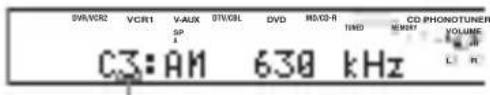
Shows the displayed station has been stored as C3.
6 Repeat steps 1 to 5 to store other stations.
Notes
- Any stored station data existing under a preset number is cleared when you store a new station under that preset number.
The reception mode (stereo or monaural) is stored along with the station frequency.
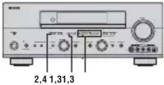
Selecting preset stations
You can tune any desired station simply by selecting the preset station number under which it was stored.
y
When performing this operation with the remote control, first press TUNER to set the remote to tuner mode.
1 Press A/B/C/D/E (NEXT) (or A/B/C/D/E i on the remote control) to select the preset station group.
The preset group letter appears in the front panel display and changes each time you press the button.

Front panel
or
Remote control
2 Press PRESET/TUNING | /h (or PRESET u /d on the remote control) to select a preset station number (1 to 8).
The preset group and number appear on the front panel display along with the station band, frequency and the TUNED indicator lights up.
Exchanging preset stations
You can exchange the assignment of two preset stations with each other. The example below describes the procedure for exchanging preset station "E1" with "A5".
1 Select preset station "E1".
See "Selecting preset stations".
2 Press and hold PRESET/TUNING (EDIT) for more than 3 seconds.
"E1" and the MEMORY indicator flash in the front panel display.

3 Select preset station "A5" using A/B/C/D/E and PRESET/TUNING | /h .
"A5" and the MEMORY indicator flash in the front panel display.
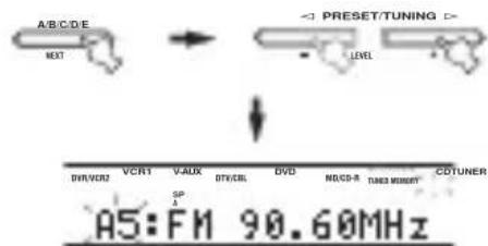
4 Press PRESET/TUNING (EDIT) again.
The stations stored at the two preset assignments are exchanged.
Receiving Radio Data System stations
Radio Data System is a data transmission system used by FM stations in many countries. The Radio Data System function is carried out among the network stations. This unit can receive various Radio Data System data such as PS (Program Service name), PTY (Program Type), RT (Radio Text), CT (Clock Time), EON (Enhanced Other Networks) when receiving Radio Data System broadcasting stations.
■PS (Program Service name) mode
The name of the Radio Data System station being received is displayed.
PTY (Program Type) mode
There are 15 program types to classify Radio Data System stations.
| NEWS | News |
| AFFAIRS | Current affairs |
| INFO | General information |
| SPORT | Sports |
| EDUCATE | Education |
| DRAMA | Drama |
| CULTURE | Culture |
| SCIENCE | Science |
| VARIED | Light entertainment |
| POP M | Pops |
| ROCK M | Rock |
| M.O.R. M | Middle-of-the-road music (easy-listening) |
| LIGHT M | Light classics |
| CLASSICS | Serious classics |
| OTHER M | Other music |
RT (Radio Text) mode
Information about the program (such as the title of the song or name of the singer) on the Radio Data System station being received is displayed using a maximum of 64 alphanumeric characters, including the umlaut symbol. If other characters are used for RT data, they are displayed with an underscore (_).
CT (Clock Time) mode
The current time is displayed and updated every minute. If the data are accidentally cut off, "CT WAIT" may appear.
■EON (Enhanced Other Networks)
See "EON function" on page 47.
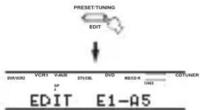
Changing the Radio Data System mode
Four modes are available for displaying Radio Data System data. The PS, PTY, RT and/or CT indicators that correspond to the Radio Data System data services offered by the station light up in the front panel display.
1 Press TUNER on the remote control to set this unit to tuner mode.

2 Press FREQ/TEXT repeatedly on the remote control to display the various Radio Data System data offered by the transmitting station.
Notes
- Do not press FREQ/TEXT until a Radio Data System indicator lights up in the front panel display. You cannot change the mode if you press the button prior to this. This is because this unit has not finished receiving all of the Radio Data System data from the station.
- Radio Data System data not offered by the station cannot be selected.
- This unit cannot utilize the Radio Data System data source if the signal received is not strong enough. In particular, the RT mode requires a large amount of data, so it is possible that the RT mode may not be displayed even if other Radio Data System modes (PS, PTY, etc.) are displayed.
- Radio Data System data may not be received under poor reception conditions. In such cases, press TUNING MODE (AUTO/MAN'L MONO) so that the AUTO indicator disappears from the front panel display. Although this will change the reception mode to manual, Radio Data System data may be displayed when you change the display to Radio Data System mode.
- If the signal strength is weakened by external interference during the reception of a Radio Data System station, the Radio Data System data service may be cut off suddenly and "...WAIT" will appear in the front panel display.
PTY SEEK function
If you select the desired program type, this unit automatically searches all preset Radio Data System stations that are broadcasting a program of the required type.
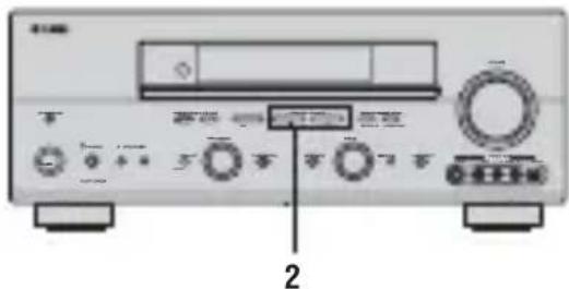
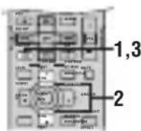
V
When performing this operation with the remote control, first press TUNER to set the remote to tuner mode.
1 Press PTY SEEK MODE on the remote control to set this unit in the PTY SEEK mode.
The program type of the station being received or "NEWS" flashes in the front panel display. To exit from the PTY SEEK mode, press PTY SEEK MODE again.

2 Press PRESET/TUNING1/h (or PRESET/CHu/d on the remote control) to select the desired program type.
The selected program type appears in the front panel display.
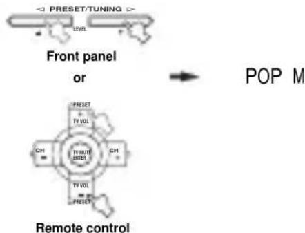
3 Press PTY SEEK START on the remote control to begin searching all preset Radio Data System stations.
The selected program type flashes and the PTY HOLD indicator lights up in the front panel display while searching for stations.
To cancel searching, press PTY SEEK START again.
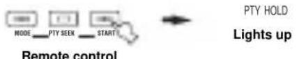
The unit stops searching when it finds a station broadcasting the selected type of program.
- If the found station is not the one you desire, press PTY SEEK START again. This unit resumes searching for another station broadcasting the same type of program.
EON function
This function uses the EON data service on the Radio Data System station network. If you select the desired program type (NEWS, INFO, AFFAIRS or SPORT), this unit automatically searches for all preset Radio Data System stations that are scheduled to broadcast the selected type of program and switches from the station currently being received to the new station when the broadcast starts.
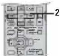
Y
When performing this operation with the remote control, first press TUNER to set the remote to tuner mode.
Note
This function can only be used when a Radio Data System station that offers the EON data service is being received. When such a station is being received, the EON indicator lights up in the front panel display.
1 Check that the EON indicator is lit in the front panel display.
If the EON indicator is not lit up, tune into another Radio Data System station so that the EON indicator lights up.
2 Press EON repeatedly on the remote control to select the desired program type (NEWS, INFO, AFFAIRS or SPORT).
The selected program type name appears in the front panel display.


NEWS
Remote control
- If a preset Radio Data System station type starts broadcasting the selected type of program, the unit automatically switches from the program being received to that program. (The EON indicator flashes.)
- When broadcasting of the selected program ends, the unit returns to the previous station (or another program on the same station).
■To cancel this function
Press EON repeatedly until no program type name is shown in the front panel display.
RECORDING
Recording adjustments and other operations are performed from the recording components. Refer to the operating instructions for those components.
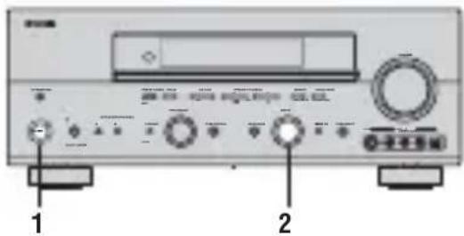

1 Turn on the power of this unit and all connected components.
2 Select the source component you want to record from.
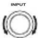
Front panel
or
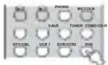
Remote control
3 Start playback (or select a broadcast station) on the source component.
4 Start recording on the recording component.
y
Do a test recording before you start an actual recording.
Notes
- When this unit is set in the standby mode, you cannot record between other components connected to this unit.
- The setting of TONE CONTROL, VOLUME, "SPEAKER LEVEL" (page 59) and programs does not affect recorded material.
- A source connected to the MULTI CH INPUT jacks of this unit cannot be recorded.
- S-video and composite video signals pass independently through this unit's video circuits. Therefore, when recording or dubbing video signals, if your video source component is connected to provide only an S-video (or only a composite video) signal, you can record only an S-video (or only a composite video) signal to your VCR.
- Digital signals input to the DIGITAL INPUT jacks are not output to the analog AUDIO OUT (L/R) jacks for recording. Likewise, analog signals input to the AUDIO IN (L/R) jacks are not output to the DIGITAL OUTPUT jack. Therefore, if your source component is connected to provide only digital (or analog) signals, you can only record digital (or analog) signals.
- A given input source is not output on the same REC OUT channel. (For example, the signal input from VCR 1 IN is not output on VCR 1 OUT.)
- Check the copyright laws in your country to record from records, CDs, radio, etc. Recording of copyrighted material may infringe copyright laws.
If you playback a video source that uses scrambled or encoded signals to prevent it from being dubbed, the picture itself may be disturbed due to those signals.
Special considerations when recording DTS software
The DTS signal is a digital bitstream. Attempting to digitally record the DTS bitstream will result in noise being recorded. Therefore, if you want to use this unit to record sources that have DTS signals recorded on them, the following considerations and adjustments need to be made.
For DVDs and CDs encoded with DTS, when your player is compatible with the DTS format, follow its operating instructions to make a setting so that the analog signal will be output from the player.
SOUND FIELD PROGRAM DESCRIPTIONS
This unit is equipped with a variety of precise digital decoders that allow you to enjoy multi-channel playback from almost any sound source (stereo or multi-channel). This unit is also equipped with a YAMAHA digital sound field processing (DSP) chip containing several sound field programs which you can use to enhance your playback experience. Most of these sound field programs are precise digital recreations of actual acoustic environments found in famous concert halls, music venues, and movie theaters.
y
The YAMAHA CINEMA DSP modes are compatible with all Dolby Digital, DTS, and Dolby Surround sources. Set the input mode to AUTO (see page 37) to enable this unit to automatically switch to the appropriate digital decoder according to the input signal.
Notes
This unit's DSP sound field programs are recreations of real-world acoustic environments made from precise measurements taken in the actual hall, etc. Thus you may notice variations in the strength of the reflections coming from the front, back, left and right.
Feel free to choose a sound field program based on your listening preference, and not purely on the name of the program itself.
For movie/video sources
You can select from the following sound fields when playing movie or video sources. The sound fields marked "MULTI" can be used with multi-channel sources, like DVD, digital TV, etc. Those marked "2-CH" can be used with 2-channel (stereo) sources like TV programs, video tapes, etc.
Program selection methods vary depending on sound field program types. For details on how to select sound field programs, see "Selecting sound field programs" on pages 32 to 36.
| Remote control button | Program Features Sources | ||
| 1 | STEREO:2ch Stereo | Downmixes multi-channel sources to 2 channel (left and right) or plays back 2-channel sources as is. | MULTI 2-CH |
| 2 | MUSIC:POP/ ROCK | This program lends an enthusiastic atmosphere to the sound, giving you the feeling you are at an actual jazz or rock concert. | |
| 3 | ENTERTAI NMENT:TV Sports | Though the presence sound field is relatively narrow, the surround sound field employs the sound environment of a large concert hall. This effect enhances the experience of watching various TV programs such as news, variety shows, music programs or sports programs. | |
| ENTERTAI NMENT:Mono Movie | This program is provided for reproducing monaural video sources (such as old movies). The program produces the optimum reverberation to create sound depth using only the presence sound field. | ||
| ENTERTAI NMENT:Game | This program adds a deep and spatial feeling to video game sounds. | ||
| 4 | MOVIE THEATER:Spectacle | CINEMA DSP processing. This program creates the extremely wide sound field of a 70-mm movie theater. It precisely reproduces the source sound in detail, making both the video and the sound field incredibly real. This is ideal for any kind of video source encoded with Dolby Surround, Dolby Digital or DTS (especially large-scale movie productions). | |
| MOVIE THEATER:Sci-Fi | CINEMA DSP processing. This program clearly reproduces dialog and sound effects in the latest sound form for science fiction films, thus creating a broad and expansive cinematic space amid silence. You can enjoy science fiction films in a virtual-space sound field that includes Dolby Surround, Dolby Digital and DTS-encoded software employing the most advanced techniques. | ||
| MOVIE THEATER:Adventure uere | CINEMA DSP processing. This program is ideal for precisely reproducing the sound design of the newest 70-mm and multi-channel soundtrack films. The sound field is made to be similar to that of the newest movie theaters, so the reverberations of the sound field itself are restrained as much as possible. | ||
| MOVIE THEATER:General | CINEMA DSP processing. This program is for reproducing sounds from 70-mm and multi-channel soundtrack films, and is characterized by soft and extensive sound field. | ||
SOUNDFIELDPROGRAM DESCRIPTIONS
| Remote control button | Program Features Sources | ||
| 5 | SUR. STANDARD | Standard processing for the selected decoder. | MULTI 2-CH |
| SUR. ENHANCED | Enhanced processing for the selected decoder. | ||
For music sources
You can select from the following sound fields when playing music sources, like CD, FM/AM broadcasting, tapes, etc.
Program selection methods vary depending on sound field program types. For details on how to select sound field programs, see "Selecting sound field programs" on pages 32 to 36.
| Remote control button | Program Features Sources | |
| 1 | STEREO:2ch Stereo | 2-channel (left and right) playback. |
| STEREO:7ch Stereo | Use to increase the output stereo sources (in stereo) from all speakers. This provides a larger sound field and is ideal for background music at parties, etc. | |
| 2 | MUSI C:Hal I in Vi enna | HiFi DSP processing. A classic shoe-box type concert hall with approximately 1700 seats. Pillars and ornate carvings create extremely complex reflections which produce a very full, rich sound. |
| MUSI C:The Bt m Line | HiFi DSP processing. This is the sound field at stage front in “The Bottom Line”, a famous New York jazz club. The floor can seat 300 people to the left and right in a sound field offering a real and vibrant sound. | |
| MUSI C:The Roxy Th r | HiFi DSP processing. The ideal program for lively, dynamic rock music. The data for this program was recorded at LA's “hottest” rock club. The listener's virtual seat is at the center-left of the hall. | |
| 3 | ENTERTAI NMENT:Di sco | HiFi DSP processing. This program recreates the acoustic environment of a lively disco in the heart of a big city. The sound is dense and highly concentrated. It is also characterized by high-energy, “immediate” sound. |
| 5 | SUR. STANDARD | Standard processing for the selected decoder. |
| SUR. ENHANCED | Enhanced processing for the selected decoder. |
ADVANCED OPERATIONS
Selecting the OSD mode
You can display this unit's operating information on a video monitor. If you display the SET MENU and sound field program parameter settings on a monitor, it is much easier to see the available options and parameters than it is by reading this information on the front panel display.
1 Turn on the video monitor connected to this unit.
2 Press ON SCREEN repeatedly to change the OSD mode.
The OSD mode changes in the following order: full display, short display, and display off.

Full display
Always shows the sound field program parameter settings as well as the contents of the front panel display.
Short display
Briefly shows the contents of the front panel display at the bottom of the screen each time you operate this unit.
Display off
Only operations performed using ON SCREEN are displayed. The OSD is displayed when using SET MENU, even if the OSD mode is set to "Display off".
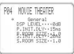
Full display
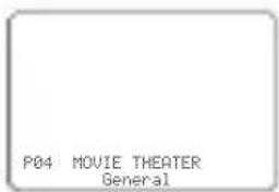
Short display
Notes
The OSD signal is not output to the REC OUT jack, and will not be recorded.
- You can set the OSD to turn on (gray background) or off when a video source is not being reproduced (or the source component is turned off) by using "DISPLAY SET" (see page 64).
- When using component video signals, the "Short display" is not output to the COMPONENT VIDEO MONITOR OUT jacks.
To display the OSD with component video signal input, set the OSD mode to "Full display" while GRAY BACK in DISPLAY SET (see page 64) is set to AUTO.
Using the sleep timer
Use this feature to automatically set this unit in the standby mode after a certain amount of time. The sleep timer is useful when you are going to sleep while this unit is playing or recording a source. The sleep timer also automatically turns off any external components connected to AC OUTLET(S).
Setting the sleep timer
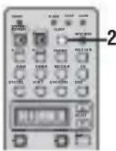
1 Select a source and start playback on the source component.
2 Press SLEEP repeatedly to set the amount of time.
Each time you press SLEEP, the front panel display changes as shown below. The SLEEP indicator flashes while switching the amount of time for the sleep timer.


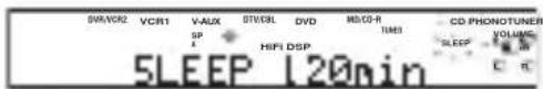
The SLEEP indicator lights up in the front panel display, and the display returns to the selected sound field program.
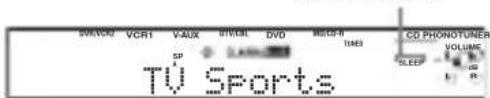
SLEEP indicator
■Canceling the sleep timer
Press SLEEP repeatedly until "SLEEP OFF" appears in the front panel display.
After a few seconds, "SLEEP OFF" disappears, and the SLEEP indicator goes off.


SLEEP OFF
y
The sleep timer setting can also be canceled by pressing STANDBY on the remote control (or STANDBY/ON on the front panel) to set this unit to the standby mode.
Manually adjusting speaker levels
You can adjust the output level of each speaker while listening to a music source. This is also possible when playing sources through the MULTI CH INPUT jacks.
Please note that this operation will override the level adjustments made in "AUTO SETUP" (page 24), "SPEAKER LEVEL" (page 59).

1 Press AMP.
2 Press LEVEL repeatedly to select the speaker you want to adjust.
FRONT L Front left speaker level
CENTER Center speaker level
FRONT R Front right speaker level
SUR. R Surround right speaker level
SUR. L Surround left speaker level
SUR. B. R Surround back right speaker level
SUR. B. L Surround back left speaker level
SWFR Subwoofer level
PRES. L Presence left speaker level
PRES. R Presence right speaker level
y
Once you press LEVEL, you can also select the speaker by pressing u /d.
3 Press j /i to adjust the speaker output level.
The control range is from +10 dB to -10 dB.
4 Press ENTER when you have completed your adjustment.
y
This operation can also be performed using the controls on the front panel. Press NEXT repeatedly to select the speaker you want to adjust, then press LEVEL - / + to adjust the output level.
SET MENU
You can use the following parameters in SET MENU to adjust a variety of system settings and customize the way this unit operates. Change the initial settings (indicated in bold under each parameter) to reflect the needs of your listening environment.
AUTO SETUP
Use to specify which speaker parameters auto setup will adjust, and to activate the auto setup procedure (see page 24).
■MANUAL SETUP
Use to manually adjust speaker and system parameters.
1 SOUND MENU
Use to manually adjust any speaker setting, alter the quality and tone of the sound output by the system or compensate for video signal processing delays when using LCD monitors or projectors.
y
Most of the parameters described in SOUND MENU are set automatically when you run auto setup (see page 24). You can use SOUND MENU to make further adjustments, but we recommend running auto setup first
| Item Features | Page | |
| A) SPEAKER SET | Selects the size of each speaker, the speakers for low-frequency signal output, and the cross over frequency. | 57 |
| B) SPEAKER LEVEL | Adjusts the output level of each speaker. | 59 |
| C) SP DI STANCE | Adjusts the delay time of each speaker. | 60 |
| D) EQUALI ZER | Adjusts the tonal quality of the center speaker. | 60 |
| E) LFE LEVEL | Adjusts the output level of the LFE channel for Dolby Digital or DTS signals. | 61 |
| F) DYNAMI C RANGE | Adjusts the dynamic range for Dolby Digital or DTS signals. | 61 |
| G) AUDIO O SET | Customizes the muting level, audio delay and tone bypass settings. | 61 |
2 INPUT MENU
Use to reassign digital input/outputs, select the input mode or rename your inputs.
| Item Features | Page | |
| A) I / O ASSI GNMENT | Assigns jacks according to the component to be used. | 62 |
| B) I INPUT MODE | Selects the initial input mode of the source. | 63 |
| C) I INPUT RENAME | Changes the name of the inputs. | 63 |
| D) VOLUME TRI M | Adjusts the output volume of each jack. | 63 |
3 OPTION MENU
Use to adjust the optional system parameters.
| Item Features Page | ||
| A) DI SPLAY SET | Adjusts the brightness of the display and converts video signals. | 64 |
| B) MEMORY GUARD | Locks sound field program parameters and other SET MENU settings. | 64 |
| C) PARAM. I NI | Initializes the parameters of a group of sound field programs. | 65 |
| D) MULTI ZONE SET | Specifies the location of the speakers connected to the SPEAKERS B terminals or selects how the ZONE 2 speakers will be amplified.* | 65 |
- The Zone 2 amplifier feature is only available for RX-V757.
■SIGNAL INFO
Use to check audio signal information (see page 37).
Using SET MENU
Use the remote control to access and adjust each parameter.
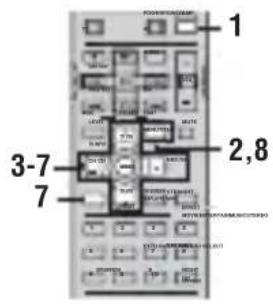
y
- You can change SET MENU parameters while the unit is reproducing sound.
- If you press a sound field program button during SET MENU operation, the SET MENU is canceled.
Note
You cannot change some SET MENU parameters while the unit is in either cinema or music night listening mode.
1 Press AMP.

2 Press SET MENU.

3 Press u /d to select MANUAL SETUP.
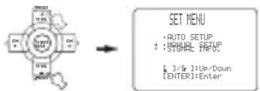
4 Press ENTER to enter MANUAL SETUP.
1 SOUND MENU appears on the front panel display.
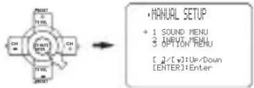
5 Press u /d to select the desired menu.
6 Press ENTER to enter the selected menu.
7 Press u /d and ENTER to select the submenu, then press u /d to select the item and j /i to change the parameter.
- Repeat this operation to select and adjust each setting.
To return to the previous menu level, press RETURN.
8 To exit, press SET MENU when finished.

Memory back-up
The memory back-up circuit prevents the stored data from being lost even if this unit is in the standby mode. However, if the power cord is disconnected from the AC outlet, or the power supply is cut for more than one week, the stored data will be lost. If so, adjust the items again.
1 SOUND MENU
Use to manually adjust any speaker setting or compensate for video signal processing delays when using LCD monitors or projectors. Most of the SOUND MENU parameters are set automatically when you run auto setup (see page 24).
1 SOUND MENU 1/2
Use to manually adjust any speaker setting.
y
If you are not satisfied with the bass sounds from your speakers, you can change these settings according to your preference.
Front speakers FRONT SP
Choices: LARGE, SMALL
- Select SMALL if you have small front speakers. The unit directs the low-frequency signals of the front channel to the speakers selected with "LFE/BASS OUT".
- Select LARGE if you have large front speakers. The unit directs the entire range of the front left and right channel signals to the front left and right speakers.
Center speaker CENTER SP
Choices: LRG, SML, NONE
- Select LRG if you have a large center speaker. The unit directs the entire range of the center channel signal to the center speaker.
- Select SML if you have a small center speaker. The unit directs the low-frequency signals of the center channel to the speakers selected with "LFE/BASS OUT".
- Select NONE if you do not have a center speaker. The unit directs all of the center channel signal to the front left and right speakers.
Surround left/right speakers SUR. L/R SP
Choices: LRG, SML, NONE
- Select LRG if you have large surround left and right speakers. The entire range of the surround channel signal is directed to the surround left and right speakers.
- Select SML if you have small surround left and right speakers. The low-frequency signals of the surround channel are directed to the speakers selected with "LFE/BASS OUT".
- Select NONE if you do not have surround speakers. This will set the unit to the Virtual CINEMA DSP mode (see page 36) and automatically set the surround back speaker setting (SUR. B L/R SP) to NONE.
Surround back speakers SUR. B L/R SP
Choices: LRGx1, LRGx2, SMLx2, SMLx1, NONE
- Select LRGx1 if you have a large surround back speaker. The unit directs the entire range of the surround back channel signal to the left surround back speaker.
- Select LRGx2 if you have 2 large surround back speakers. The unit directs the entire range of the surround back channel signal to the surround back speakers.
- Select SMLx2 if you have 2 small surround back speakers. The low-frequency signals of the surround back channels are directed to the speakers selected with "LFE/BASS OUT".
- Select SMLx1 if you have a small surround back speaker. The low-frequency signals of the surround back channel are directed to the speakers selected with "LFE/BASS OUT", and the rest of the frequency signals are directed to the left surround back speaker.
- Select NONE if you do not have a surround back speaker. The unit directs all of the surround back channel signal to the surround left and right speakers.
Note
If you select SMLx1 or LRGx1, connect the speaker to the left. SURROUND BACK speaker terminals.
Presence speakers PRESENCE SP
Choices: YES, NONE
- Select YES if you have presence speakers.
- Select NONE if you do not have presence speakers.
y
When YES is selected, the unit automatically adjusts the dialog lift parameter. To adjust it manually, see page 92.
Bass out LFE/ BASS OUT
Low-frequency (bass) signals can be directed to the subwoofer and/or the front left and right speakers according to the characteristics of your system. This setting also determines the routing of the LFE (low-frequency effect) signals found in Dolby Digital or DTS sources.
Choices: SWFR, FRNT, BOTH
- Select SWFR if you connect a subwoofer. LFE and low-frequency signals from other channels are directed to the subwoofer according to the speaker settings.
- Select FRNT if you do not use a subwoofer. LFE and low frequency signals from other channels are directed to the front speakers according to the speaker settings (even if you have previously set front speakers to SML).
- Select BOTH if you connect a subwoofer and you want to output low-frequency signals from front channels to both the front speakers and subwoofer. LFE and low-frequency signals from other channels are also directed to the subwoofer according to the speaker settings. Use this function to reinforce low-frequency signals using the subwoofer when playing back sources such as CDs.
Cross over CROSS OVER
Use this feature to select a cross-over (cut-off) frequency for all low-frequency signals. All frequencies below the selected frequency will be sent to the subwoofer. Choices: 40Hz , 60Hz , 80Hz , 90Hz , 100Hz , 110Hz , 120Hz , 160Hz , 200Hz

Subwoofer phase SUBWOOFER PHASE
If bass sounds are lacking or unclear, use this feature to switch the phase of your subwoofer.
Choices: NORMAL, REVERSE
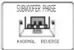
- Select NORMAL if you do not want to reverse the phase of your subwoofer.
- Select REVERSE to reverse the phase of your subwoofer.
Presence/Surround back channel priority
PRIORI TY
You can select to prioritize either the surround back or presence speakers when playing sources that contain surround back channel signals using CINEMA DSP sound field programs.
Choices: PRch, SBch
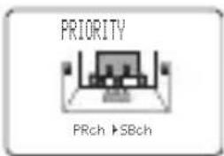
- Select PRch to use presence speakers even when surround back channel signals are input. The signals for the surround back channel will be output from surround speakers.
- Select SBch to use surround back speakers when a surround back channel signal is detected in a CINEMA DSP program. Presence channel signals will be output from front speakers.
Use these settings to manually balance the speaker level of each speaker selected in SPEAKER SET (page 57).
Choices: -10.0dB to +10.0dB
Initial setting: 0 dB
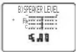
- FL adjusts the balance of the front left speaker.
- FR adjusts the balance of the front right speaker.
- C adjusts the balance of the center speaker.
- SL adjusts the balance of the surround left speaker.
- SR adjusts the balance of the surround right speaker.
- SBL * adjusts the balance of the surround back left speaker.
- SBR * adjusts the balance of the surround back right speaker.
- SWFR adjusts the balance of the subwoofer.
- PL adjusts the balance of the presence left speaker.
- PR adjusts the balance of the presence right speaker.
Instead of SBL and SBR, SB will be displayed if you selected only one surround back speaker in SUR. B L/R SP (page 58).
■Speaker distance C) SP DI STANCE
Use this feature to manually input the distance of each speaker and adjust the delay applied to respective channel. Ideally, each speaker should be the same distance from the main listening position. However, this is not possible in most home situations. Thus, a certain amount of delay must be applied to the sound from each speaker so that all sound will arrive at the listening position at the same time.

Unit UNI T
Choices: meters (m), feet (ft)
- Select meters to input speaker distances in meters.
- Select feet to input speaker distances in feet.
Speaker distances
Choices: 0.3 to 24.0m
- FRONT L adjusts the distance of the front left speaker.
Initial setting: 3.0m
- FRONT R adjusts the distance of the front right speaker. Initial setting: 3.0m
- CENTER adjusts the distance of the center speaker.
Initial setting: 3.0m
- SUR. L adjusts the distance of the surround left speaker. Initial setting: 3.0m
- SUR. R adjusts the distance of the surround right speaker. Initial setting: 3.0m
- SB L * adjusts the distance of the surround back left speaker. Initial setting: 2.10m
- SB R * adjusts the distance of the surround back right speaker. Initial setting: 2.10m
- SWFR adjusts the distance of the subwoofer. Initial setting: 3.0m
- PRES L adjusts the distance of the presence left speaker. Initial setting: 3.0m
- PRES R adjusts the distance of the presence right speaker. Initial setting: 3.0m
* Instead of SB L and SB R, SUR. B will be displayed if you selected only one surround back speaker in SUR. B L/R SP (page 58).
Center graphic equalizer D) EQUALI ZER
Use this feature to select the parametric (AUTO PEQ) or graphic equalizer (CNTR GEQ).
Equalizer EQ TYPE SELECT
Select to change the type of equalizer used by this unit. Choices: AUTO PEQ, CNTR GEQ, EQ OFF
- Select AUTO PEQ to use the equalizer adjusted in auto setup.
- Select CNTR GEQ to adjust the built-in 5-band graphic equalizer so that the tonal quality of the center speaker matches that of the front left and right speakers.
- Select EQ OFF to cancel equalizing.
Center graphic equalizer CENTER GEQ
When CNTR GEQ is selected, use this feature to output a test tone and adjust the tonal quality so that it matches that of the front left speaker.
You can adjust 5 frequency bands:
100Hz, 300Hz, 1kHz, 3kHz, 10kHz
Choices: -6 to +6 dB
Initial setting: 0 dB
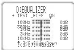
- Select ON to output test tones from the front left and center speakers, and adjust the tonal quality of the center speaker.
- Select OFF to stop the test tone and output the currently selected source component.
Press u /d to select a frequency band. - Press j / i to adjust the selected frequency band.
Low-frequency effect level E) LFE LEVEL
Use to adjust the output level of the LFE (low-frequency effect) channel according to the capacity of your subwoofer or headphones. The LFE channel carries low-frequency special effects which are only added to certain scenes. This setting is effective only when this unit decodes Dolby Digital or DTS signals. Choices: -20 to 0 dB
E)LFLELEVEL
SPEAKER... ...0dB
HEADFPOHPON... ...0dB
[[]]UP/Down
[[]]RAdjust
Speaker SPEAKER
Select to adjust the speaker LFE level.
Headphone HEADPHONE
Select to adjust the headphone LFE level.
Note
Depending on the settings of "LFE LEVEL", some signals may not be output from the SUBWOOFER OUTPUT jack.
Dynamic range F) DYNAMIC RANGE
Use to select the amount of dynamic range compression to be applied to your speakers or headphones. This setting is effective only when the unit is decoding Dolby Digital and DTS signals.
Choices: MIN (minimum), STD (standard), MAX (maximum)
F)DYNAMIC RANGE
+能!MINSTB
E
Speaker SP
Select to adjust the speaker compression.
Headphone HP
Select to adjust the headphone compression.
- Select MIN if you regularly listen at low volume levels.
- Select STD for general use.
- Select MAX to preserve the greatest amount of dynamic range.
Audio settings G) AUDIO SET
Use to customize this units overall audio settings.
6)AUDIO SET
→MUTING TYPE·FULLOUIDATE
AODTO DELRY·*BMS TONE BYPASS·AUTO
[]/][v]Up/Down
[[]Select
Muting type MUTING TYPE
Use to adjust how much the mute function reduces the output volume.
Choices: FULL, -20dB
- Select FULL to completely halt all output of sound.
- Select -20dB to reduce the current volume by 20 dB.
Audio delay AUDIOO DELAY
Use to delay the sound output and synchronize it with the video image. This may be necessary when using certain LCD monitors or projectors.
Choices: 0 to 160ms
Tone bypass TONE BYPASS
Use to select whether audio output bypasses tone control circuitry when TREBLE and BASS are set to 0 dB (see page 31).
Choices: AUTO, OFF
- Select AUTO if you want signals to bypass tone control circuitry to provide the purest signal possible.
- Select OFF if you do not want signals to bypass tone control circuitry.
2 INPUT MENU
Use to reassign digital input/outputs, select the input mode or rename your inputs.
■Input/output assignment
A) I/O ASSIGNMENT
You can assign jacks according to the component to be used if this unit's initial settings do not correspond to your needs. Change the following parameters to reassign the respective jacks and effectively connect more components. Once the inputs have been reassigned, you can select the corresponding component by using INPUT on the front panel or the input selector buttons on the remote control.
For COMPONENTVIDEOjacksA(CMPNT-V I NPUT[A])andB(CMPNT-VI NPUT[B])
Choices: [A] DVD, DTV/CBL, V-AUX, VCR1, DVR/VCR2 [B] DVD, DTV/CBL, V-AUX, VCR1, DVR/VCR2
![YAMAHA RXV757 - For COMPONENTVIDEOjacksA(CMPNT-V I NPUT[A])andB(CMPNT-VI NPUT[B]) - 1](/content/2026/02/379053/images/45b662b901e70ec3d518d5c8c0c422e9d7e61aef0b027fed758b7ff5afd9dd6b.jpg)
For OPTICAL OUTPUT jack 1 (OPTICAL OUT (1))
Choices:PHONO,CD,MD/CD-R,DVD,DTV/CBL V-AUX,VCR1,DVR/VCR2
For OPTICAL INPUT jack 2 (OPTICAL IN (2)), 3 (OPTICAL IN (3)) and 4 (OPTICAL IN (4))
Choices: (2) PHONO, CD, (TUNER*), MD/CD-R, DVD, DTV/CBL, VCR1, DVR/VCR2
(3)PHONO,CDTUNER*MD/CD-R,DVD DTV/CBL,VCR1,DVR/VCR2 (4)PHONO,CD(TUNER*),MD/CD-R,DVD, DTV/CBL,VCR1,DVR/VCR2
- DSP-AX757SE only
For COAXIAL INPUT jacks 5 (COAXI AL IN (5)) and 6 (COAXI AL IN (6))
Choices: (5) PHONO, CD, (TUNER), MD/CD-R, DVD, DTV/CBL, V-AUX, VCR1, DVR/VCR2 (6) PHONO, CD, (TUNER), MD/CD-R, DVD, DTV/CBL, V-AUX, VCR1, DVR/VCR2 *DSP-AX757SE only
Notes
- You cannot select a specific item more than once for the same type of jack.
- When you connect a component to both the COAXIAL and OPTICAL jacks, priority is given to the input signals from the COAXIAL jack.
■Input mode B) I NPUT MODE
Use this feature to designate the input mode for sources connected to the DIGITAL INPUT jacks when you turn on this unit (see page 37 for details about the input mode). Choices: AUTO, LAST
B>INPUT MODE
AUTO LAST
白白
- Select AUTO to allow this unit to automatically detect the type of input signal and select the appropriate input mode.
- Select LAST to set this unit to automatically select the last input mode used for that source.
Note
Even if LAST is selected, the last setting for the EX/ES button will not be recalled.
■Input rename C) I NPUT RENEAME
Use this feature to change the name of the inputs on the OSD and front panel display.
C)INPUTRENAME
DUD DUD
[1] [2] 把此值计算
1 Press an input selector button to select the input you want to change the name of.
2 Press AMP.
3 Press j /i to place the (under-bar) under the space or the character you want to edit.
4 Press u /d to select the character you want, then use j /i to move to the next space.
- You can use up to 8 characters for each input.
- Press d to change the character in the following order, or press u to go in the reverse order: A to Z, a space, 0 to 9, a space, a to z, a space, symbols (#, *, -, +, etc.)
5 Repeat steps 1 through 4 to rename each input.
6 To exit, press SET MENU when finished.
Volume Trim D) VOLUME TRI M
Use this feature to adjust the level of the signal input to each jack. This is useful if you want to balance the level of each input source to avoid sudden changes in volume when switching between input sources.
Choices: PHONO, CD, MD/CD-R, TUNER, DVD, DTV/CBL, V-AUX, VCR1, DVR/VCR2
3 OPTION MENU
Use to adjust the optional system parameters.
■Display settings A) DI SPLAY SET

Dimmer DI MMER
Use to adjust the brightness of the front panel display. Choices: -4 to 0
Video conversion VI DEO CONV.
Use this feature to turn on/off conversion of composite (VIDEO) signals to both S-video and component signals. This allows you to output converted video signals from the SVIDEO or COMPONENT VIDEO jacks when no S-video or component signals are input. This feature also converts S-video signals to component signals when no component signals are input.
Choices: ON, OFF
- Select OFF not to convert any signals (except S-video signals to composite signals).
- Select ON to convert composite signals to S-video and component signals, and to convert S-video signals to component signals.
- Regardless of the setting, S-video signals are always converted to composite signals.
Notes
- Converted video signals are only output to the MONITOR OUT jacks. When recording you must make the same type of video connections (i.e., S-video) between each component.
- When converting composite video or S-video signals from a VCR to component video signals, the picture quality may suffer depending on your VCR.
OSD shift OSD SHI FT
Use to adjust the vertical position of the OSD.
Choices: +5 (downward) to -5 (upward)
- Press + to lower the position of the OSD.
- Press - to raise the position of the OSD.
Gray back GRAY BACK
Selecting AUTO for the on-screen display setting displays a gray background when there's no video signal input. Nothing is displayed if OFF is selected. Choices: AUTO, OFF
Notes
- When only the component video signals are input, the OSD is not displayed if GRAY BACK is set to OFF. To display the OSD with component video signal input, set GRAY BACK to AUTO while the OSD mode (see page 52) is set to "Full display".
- When video signals are not being input, set GRAY BACK to AUTO to display the OSD.
Component OSD CMPNT OSD
Use this feature to turn on/off OSD output to the COMPONENTVIDEOMONITOROUTjacks when using the SET MENU.
Choices: ON, OFF
- Select ON to output the OSD signals from COMPONENTVIDEO MONITOR OUT jacks.
- Select OFF if you do not want to output the OSD signals from COMPONENTVIDEO MONITOR OUT jacks.
Note
SET MENU functions even when OFF is selected.
■Memory guard B) MEMORY GUARD
Use this feature to prevent accidental changes to DSP program parameter values and other system settings. Choices: OFF, ON
Select ON to protect:
DSP program parameters
- All SET MENU items
All speaker levels
The on-screen display (OSD) mode
Note
When MEMORY GUARD is set to ON, you cannot select any other SET MENU items.
Parameter initialization C) PARAM. I NI
Use this feature to initialize the parameters for each sound field program within a sound field program group. When you initialize a sound field program group, all of the parameter values within that group revert to their initial settings.
Press the corresponding numeric button for the sound field program that you want to initialize.
Choices:
An asterisk (^*) appears next to program numbers that have been changed from their initial settings.
Choices: STEREO, MUSIC, ENTERTAINMENT, MOVIE, STANDARD
C)PARM.INI
STEREO
SISI
MOHTEHEATER
+STANDARD
Press DSP Key
Notes
- You cannot automatically revert to the previous parameter
settings once you initialize a sound field program group. - You cannot separately initialize individual sound field programs.
- You cannot initialize any program groups when "MEMORY GUARD" is set to ON.
Zone set D) MULTI ZONE SET
Use to specify the location of speakers connected to the SPEAKERS B terminals.
D)MULTI ZONE SET
→SPB·FRONT
ZONE2 AMP-EXT
[<]/[>]:Select
Speaker B setting SP B
Use this feature to select the location of the front speakers connected to the SPEAKERS B terminals.
Choices: FRONT, ZONE B
- Select FRONT to turn on/off SPEAKERS A and B when the speakers connected to the SPEAKERS B terminals are set in the main room.
- Select ZONE B if the speakers connected to the SPEAKERS B terminals are set in another room. If SPEAKERS A is turned OFF and SPEAKERS B is turned ON, all the speakers including the subwoofer in the main room are muted and the unit outputs sound from SPEAKERS B only.
Notes
- If you connect headphones to the PHONES jack on the unit when "SP B" is set to ZONE B, the sound is output from both headphones and SPEAKERS B.
- If a DSP program is selected when "SP B" is set to ZONE B, the unit automatically enters the Virtual CINEMA DSP mode.
Zone 2 amplifier ZONE2 AMP
(RX-V757 only)
Use to select how the ZONE 2 speakers will be amplified.
Choices: INT,EXT
- Select EXT if you do not use Zone 2 speakers or if you connect your Zone 2 speakers through an external amplifiers connected to this unit's ZONE 2 OUTPUT jacks.
- Select INT to use this unit's internal amplifier if you connect your Zone 2 speakers directly to this unit's PRESENCE/ZONE 2 speaker terminals.
ADVANCED SETUP MENU
The ADVANCED SETUP menu is displayed in the front panel display.
y During the advanced setup procedure, audio output is muted.
- During the advanced setup procedure, only the STANDBY/ON, STRAIGHT (EFFECT) buttons, and PROGRAM selector on the front panel are available for operation.
CAUTION
Be sure to set the speaker impedance before using this unit to play back audio or video signals.
1 Turn off the power to this unit, and while holding down STRAIGHT (EFFECT), press STANDBY/ON.
This unit turns on, and the ADVANCED SETUP menu appears in the front panel display.

STRAIGHT
While holding down, press

2 Rotate PROGRAM to move through the menu and select the item you want to set up.
See the end of this section for a complete list of available parameters.

PROGRAM
3 Press STRAIGHT (EFFECT) repeatedly to toggle between the available parameters.

STRAIGHT
4 Press STANDBY/ON to confirm your selection.

This completes the advanced setup procedure.
The settings you made are reflected the next time this unit's power is turned on.
■ADVANCED SETUP menu items
Change the initial settings (indicated in bold under each parameter) to reflect the needs of your listening environment.
Speaker impedance SP IMP.
Use to switch the speaker impedance for this unit. Choices: 8Ω MIN, 4Ω MIN
- Select 8 MIN to set the speaker impedance to 8
- Select 4 MIN to set the speaker impedance to 4
Remote REMOTE
Use to switch the ID for the remote control of this unit.
Choices: ID1, ID2
- Select ID1 to operate this unit using the default code.
- Select ID2 to operate this unit using an alternative code.
Note
You must also make settings for the remote control (see page 69).
| SP IMP. | Speaker Impedance | level |
| 4 Ω MIN | Front | If you use one set (A or B), the impedance of each speaker must be 4 Ω or higher. |
| If you use two sets (A and B), the impedance of each speaker must be 8 Ω or higher. | ||
| Center | The impedance of each speaker must be 6 Ω or higher. | |
| Surround | ||
| Surround back | ||
| 8 Ω MIN | Front | If you use one set (A or B), the impedance of each speaker must be 8 Ω or higher. |
| If you use two sets (A and B), the impedance of each speaker must be 16 Ω or higher. | ||
| Center | The impedance of each speaker must be 8 Ω or higher. | |
| Surround | ||
| Surround back |
Factory presets PRESET
Use to reset all parameters to the factory presets (see page 91).
Choices: CANCEL, RESET
- Select CANCEL if you do not want this unit's parameters to be initialized when you reset the factory presets.
- Select RESET if you want all of this unit's parameters to be initialized when you reset the factory presets.
Note
This setting does not affect ADVANCED SETUP menu item parameters.
REMOTE CONTROL FEATURES
In addition to controlling this unit, the remote control can also operate other A/V components made by YAMAHA and other manufacturers. To control other components, you must set up remote control with the appropriate remote control codes. This remote control also has a learn feature which allows the remote to acquire functions from other remote controls equipped with an infrared remote control transmitter.
Control area
Controlling this unit
The shaded areas below can be used to control this unit after pressing AMP to activate the AMP mode.
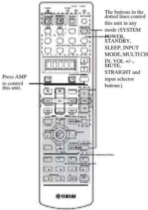
Fixing the remote to AMP mode
You can fix the remote permanently to AMP mode (fixed AMP mode) so that the shaded areas above always control this unit.
This is useful, if you primarily want to use the remote control in AMP mode. To fix AMP mode, hold down AMP for at least 3 seconds so that "A:_" appears in the display window.
A:DVD
Fixed AMP mode

DVD
Component control mode
To temporarily switch to component control mode, press AMP. To cancel fixed AMP mode, hold down AMP for at least 3 seconds.
Controlling other components
The shaded areas below can be used to control other components. Each button has a different function depending on the selected component. Select the component you want to control by pressing an input selector button or SELECT k/n. The name of the selected component appears in the display window.
The A/B and input selector buttons switch the function of the component control area below.
Use the A/B buttons to control other components regardless of whether they are connected to this unit. Factory setting:
A...LD player B...CD recorder
SELECT k/n switches control to another component without changing the input source on this unit.
Component control area
You can control up to 11 different components by setting appropriate remote control codes (see page 69).
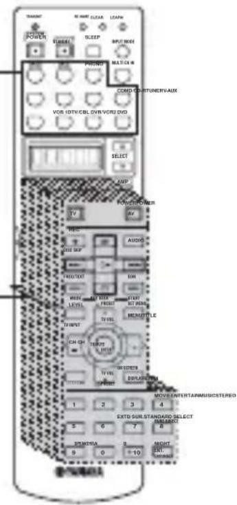
Setting remote control codes
You can control other components by setting the appropriate manufacturer codes. Codes can be set up for each input area.
The following table shows the factory preset component (Library: component category) and the remote control code for each area.
Remote Control Code Default Settings
| Input area | Component category (Library) | Manufacturer |
| A | L | D Y |
| B | C | D - |
| PHONO | TV | - |
| V-AUX | VCR | - |
| TUNER TURNER Yamaha-3 | ||
| MD/CD-R MD | Yamaha-1 | |
| CD CD Yamaha-1 | ||
| DTV/CBL TV | ||
| VCR 1 VCR | ||
| DVR/VCR2 DVR Yamaha | ||
| DVD | DVD Yamaha a l | |
Note
You may not be able to operate your YAMAHA component even if a YAMAHA remote control code is initially set as listed above. In this case, try to set other YAMAHA remote control code(s).
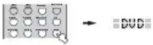
1 Press an input selector button to select the source component you want to set up.
2 Press and hold LEARN for about 3 seconds using a ballpoint pen or similar object.
"SETUP" and the selected component name appear alternately in the display window.
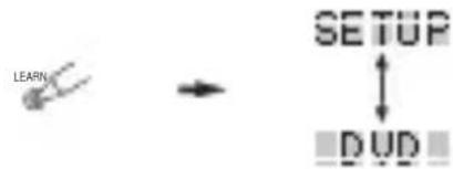
Be sure to press and hold LEARN for at least 3
a seconds, otherwise the learning process will start.
Y a m a Complete each of the following steps in 30 seconds. Otherwise, the learning mode will be automatically canceled. In this case, press LEARN again.
If you want to change a library (component category), press j / i. You can set a different type of component.
Library choices:L:DVD,L:DVR,L:LD,L:CD, L:CDR, L:MD, L:TAP (tape), L:TUN, L:AMP*, L:TV, L:CAB (cable), L:DBS, L:SAT, L:VCR
The amplifier Library (L:AMP) code is preset to "ID1" to operate this unit. However, you can switch between the following two codes if necessary.
The initial setting for "Amplifier library" is "ID1".
| AMP library code (remote control setting) | Function | Remote control ID (this unit's setting: see page 67) |
| ID1(initial setting) | To operate this unit using the default code. | ID1(initial setting) |
| IDTZ | To operate this unit using the default code.To operate Zone 2 or Zone 3 features (see page 76).(RX-V757 only) | |
| ID2 | To operate this unit using an alternative code. | ID2 |
| ID2Z | To operate this unit using an alternative code.To operate Zone 2 or Zone 3 features (see page 76).(RX-V757 only) |
When using multiple YAMAHA receivers/amplifiers, you may be able to operate the other components simultaneously with the default code setting. In this case, set one of the alternative codes to operate this unit separately
3 Press u /d to select the name of your component's manufacturer.
You will find the names of most worldwide audio-video manufacturers in alphabetical order in the display window.
4 Press one of the buttons shaded below to see if you can control your component. If you can, the remote control code is correct.
If the manufacturer of your component has more than one codes, try each of them until you find the correct one.
- If you continuously want to set up a code for another component, press TV MUTE/ENTER and repeat steps 1, 3 and 4.
5 Press LEARN again to exit from the setup mode.

Notes
- The supplied remote control does not contain all possible manufacturer codes for commercially available AV components (including YAMAHA AV components). If operation is not possible with any of the manufacturer codes, program the new remote control function with the Learn feature (see below) or use the remote control supplied with the component.
- If you have already programmed a remote control function for a button, the function by learning programming takes priority over the setup remote control code's function.
- "ERROR" appears in the display window if you press a button not indicated in the respective step, or when you press more than one button at the same time.
Controlling other components
Once you set the appropriate remote control codes, you can use this remote to control your other components. Note that some buttons may not correctly operate the selected component. Use the input selector buttons to select the component you want to operate. The remote control automatically switches to the appropriate control mode for that component.
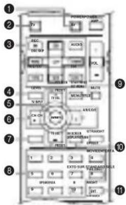
| DVD player/DVD recorder | VCR | Digital TV/Cable TV | LD player CD player | MD/CD recorder | Tuner | ||
| 1 AV POWER | Power * 1 | Power *2 | VCR power *3 | Power *3 | Power *4 | Power *1 | Power *1 |
| 2 TV POWER | TV power *2 | TV power *2 | TV power | TV power *2 | TV power *2 | TV power *2 | TV power *2 |
| 3 REC/DISC SKIP | Disc skip (player)Rec (recorder) | Rec | VCR rec *3 | Disc skip | Rec (MD) | ||
| h | Play | Play | VCR play *3 | Play | Play | Play | |
| I I | Search backward | Search backward | VCR search backward *3 | Search backward | Search backward | Search backward | |
| h h | Search forward | Search forward | VCR search forward *3 | Search forward | Search forward | Search forward | |
| AUDIO | Audio | Sound | |||||
| e | Pause e | Pause | VCR pause *3 | Pause | Pause | Pause | |
| b | Skip backward | Skip backward | Skip backward | Skip backward | |||
| a | Skip forward | Skip forward | Skip forward | Skip forward | |||
| s | Stop | Stop | VCR stop *4 | Stop | Stop | Stop | |
| 4 TITLE/TV INPUT | Title | TV input *2 | TV input | TV input *2 | TV input *2 | TV input *2 | |
| 5 TV MUTE/ENTER | Select | TV mute *2 | TV mute | TV mute *2 | TV mute *2 | TV mute *2 | |
| 6 TV VOL + | Up | TV volume + *2 | TV volume + | TV volume + *2 | TV volume + *2 | TV volume + *2 | Preset up (1-8) |
| TV VOL - | Down | TV volume - *2 | TV volume - | TV volume - *2 | TV volume - *2 | TV volume - *2 | Preset down (1-8) |
| CH + | Right | VCR channel + | TV channel + | TV channel + *2 | TV channel + *2 | TV channel + *2 | Preset up (A-E) |
| CH - | Left | VCR channel - | TV channel - | TV channel - *2 | TV channel - *2 | TV channel - *2 | |
| 7 RETURN | Return | ||||||
| 8 1-9,0,+10 | Numeric buttons | Numeric buttons | Numeric buttons | Numeric buttons | Numeric buttons | Numeric buttons | Preset stations (1-8) |
| 9 MENU | Menu | ||||||
| 0 DISPLAY | Display | Display | Display | Display | Display | ||
| A ENT. | Title/Index | Enter | Enter | Chapter/Time | Index | Index | |
1 This button functions only when the original remote control of the component has a POWER button.
^2 These buttons can operate your TV without switching the input if the remote control code is set in DTV/CBL or PHONO. When the remote control code for your TV is set up in both the DTV/CBL and PHONO areas, priority is given to the signal in the DTV/CBL area.
*3 These buttons can operate your VCR without switching the input to VCR 1 if the remote control code is set in VCR 1.
Programming codes from other remote controls
If you want to program functions not included in the basic operations covered by the remote control code, or an appropriate remote control code is not available, do the following. You can program any of the buttons available in the component control area (see page 68). The buttons can be programmed independently for each component.
Note
This remote control transmits infrared rays. If the other remote control also uses infrared rays, this remote control can learn most of its functions. However, you may not be able to program some special signals or extremely long transmissions. (Refer to the operating instructions for the remote control of your component.)
1 Press an input selector button to select a source component.
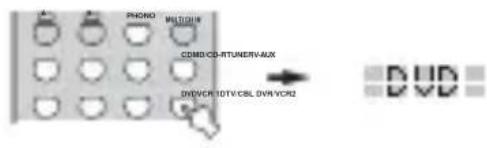
2 Place this remote control about 5 to 10cm apart from the other remote control on a flat surface so that their infrared transmitters are aimed at each other.
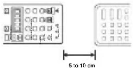
3 Press LEARN using a ballpoint pen or similar object.
Do not press and hold LEARN. If you hold it down for more than three seconds, the remote enters the remote control code setting mode.

y
Complete each of the following steps in 30 seconds. Otherwise, the learning mode will be automatically canceled. In this case, press LEARN again.
4 Press the button at which you want to program the new function.
"LEARN" is displayed.
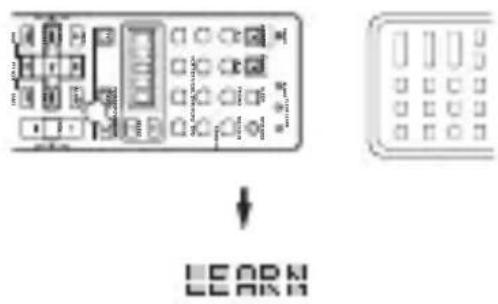
5 Press and hold the button you want to program on the other remote control until "OK" appears in the display window.
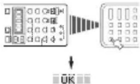
Notes
- "NG" appears in the display window if programming was unsuccessful. In this case, start over from step 4.
- This remote control can learn approximately 120 functions. However depending on the signals learned, "FULL" may appear in the display before you program 120 functions. In this case, clear unnecessary programmed functions to make room for further learning.
6 Repeat steps 4 and 5 to program additional functions.
7 Press LEARN again to exit from the learning mode.

Notes
- Learning may not be possible in the following cases:
- When the batteries in the remote control for this unit or other components are weak.
- When the distance between the two remote controls is too great or too small.
- When the remote control infrared windows are not facing at the appropriate angle.
- When the remote control is exposed to direct sunlight.
- When the function to be programmed is continuous or uncommon.
- "ERROR" appears in the display window if you press more than one button at the same time.
Changing source names in the display window
You can change the name that appears in the display window on the remote control if you want to use a different name to the one that is set as the factory preset.
This is useful when you have set the input selector to control a different component.
1 Press an input selector button to select the source component you want to rename.
The selected component name appears in the display window.
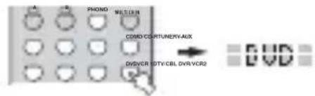
2 Press RE-NAME using a ballpoint pen or similar object.

3 Press u /d to select and enter a character.
Pressing d changes the character as follows:
A to Z, a to z, 0 to 9, space, -(hyphen), and /(slash).
(Pressing u changes the characters in reverse order.)

4 Press j / i to move the cursor to the next position.
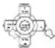
y
If you want to continue setting up names for other components, press TV MUTE/SELECT and repeat steps 1, 3 and 4.
5 Press RE-NAME again to exit from the renaming mode.

Clearing function sets
You can clear all changes made in each function set, such as learned functions, renamed source names and setup manufacturer codes.
1 Press CLEAR by using a ballpoint pen or similar object.

Complete each of the following steps in 30 seconds. Other wise, the learning mode will be automatically canceled. In this case, press CLEAR again.
2 Press u /d to select the clear mode.
L: DVD (L: name of a component)
Cleared all learned functions in the respective
component control area. Press an input selector
button to select the component.
L: AMP Casks all learned functions for this unit's control area.
L:ALL Clears all learned functions.
RNAME Clears all renamed source names.
FCTRY Clears all remote functions and returns the remote
to the factory settings.
3 Press and hold CLEAR again for about 3 seconds.
"C:OK" appears in the display window.
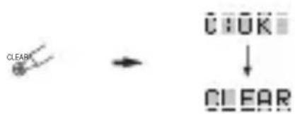
Note
"C:NG" appears in the display window if the operation is unsuccessful. In this case, start over from step 2.
4 Press CLEAR to exit from the clearing mode.
Once you have cleared a learned function for a button, the button reverts to the factory preset setting.

Note
"ERROR" appears in the display window under the following circumstances:
- When a button other than the cursor is pressed.
- When more than one button is pressed at the same time.
Clearing individual functions
■ Clearing a learned function
You can clear the function learned in a certain programmed button in each area.
4 Repeat step 3 to clear other learned functions.
5 Press LEARN again to exit.
1 Press an input selector button to select the source component containing the function you want to clear.
The selected component name appears in the display window.

2 Press LEARN using a ballpoint pen or similar object.
"LEARN" and the selected component name appear alternately in the display window.

y Complete each of the following steps in 30 seconds. Otherwise the learning mode will be automatically canceled. In this case, press LEARN again.
3 Press and hold CLEAR using a ballpoint pen or similar object, then press the button you want to clear for about 3 seconds.
"C:OK" appears in the display window.
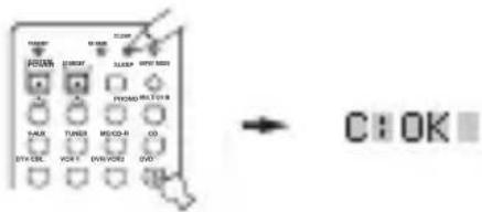
When you clear a learned function, the button reverts to the factory preset setting (or manufacturer setting if you have set manufacturer codes).
ZONE 2 (RX-V757 ONLY)
This unit allows you to configure a multi-room audio system. You can control this unit from the second room using the supplied remote control.
Only analog signals are sent to the second room. Any source you want to listen to in the second room must be connected using the analog (AUDIO L/R) input jacks on this unit.
Zone 2 connections
You need the following additional equipment to use the multi-room functions of this unit:
An infrared signal receiver in the second room.
- An infrared emitter in the main room. This emitter transmits the infrared signals from the remote control in the second room to the main room (to a CD player, for example).
- An amplifier and speakers for the second room.
y
- Since there are many possible ways to connect and use this unit in a multi-room installation, we recommend that you consult with your nearest authorized YAMAHA dealer or service center about the Zone 2 connections that best meet your requirements.
- Some YAMAHA models are able to connect directly to the REMOTE CONTROL OUT jack of this unit. If you own these products, you may not need to use an infrared emitter. Up to 6 YAMAHA components can be connected as shown.
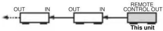
System configuration and connections example
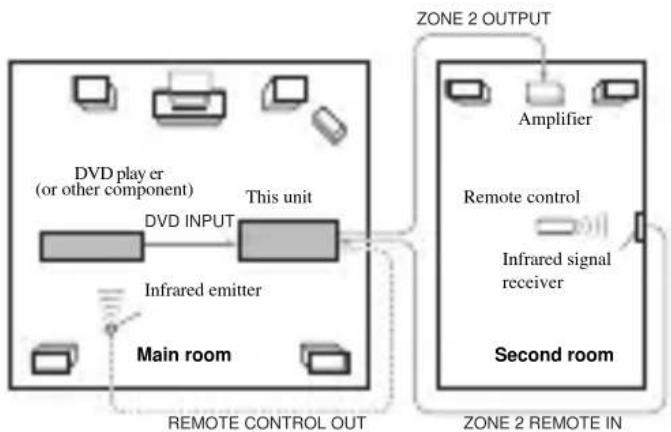
Notes
- When not using the main room, turn down the volume of this unit in the main room. Adjust the volume control on the amplifier in the second room.
- To avoid unexpected noise, DO NOT USE the Zone 2 feature with CDs encoded in DTS.
Using this unit's internal amplifier
To use this unit's internal amplifier, set "ZONE2 AMP" to "INT" in SET MENU (see page 65).
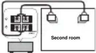
This unit
Remote controlling Zone 2
The supplied remote control can be used to control Zone 2. You can even select the input source and control components located in the main room directly from the second room regardless of the listening condition in the main room.
y
You can also turn on/off the MAIN and Zone 2 mode by pressing MAIN or ZONE 2 on the front panel.
To enable Zone 2 mode on the remote control
You will be able to switch the remote control mode from one room to another, and use STANDBY, SYSTEM POWER, MUTE and VOL - / + to control the selected room.
1 Repeat steps 1 and 2 of the procedure in "Setting remote control codes" on page 69.
2 Press j /i to select "L:AMP".
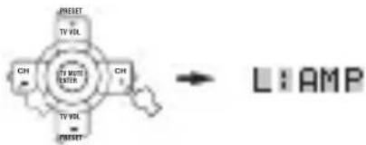
3 Press u /d to select "ID1Z".
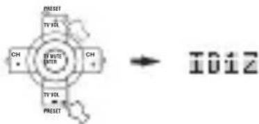
Notes
To select the Zone feature with ID2, select "ID2Z".
- Since the Zone 2 code is common to "ID1Z" and "ID2Z", the Zone 2 code does not change even if the AMP library code (remote control setting) is switched.
4 Press LEARN to complete the Zone setup.
The remote control will be able to operate this unit and Zone 2.

■To control Zone 2
1 Press SELECT k repeatedly to display "ZONE2" in the display window.

2 Press SYSTEM POWER to turn Zone 2 power on.
3 Press an input selector button to select the input source you want to listen to in the second room.
The display window shows "2: name of selected input" if the remote control is in the Zone 2 mode.
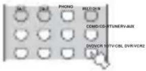
4 You can control Zone 2 using the input selector, STANDBY, SYSTEM POWER, MUTE and VOL - / +
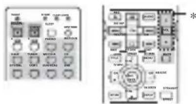
- If “ZONE2 AMP” in OPTION MENU is set to INT, you can use VOL - / + to adjust sound output from speakers connected to the PRESENCE/ZONE 2 speaker terminals (see page 65). However, VOL - / + cannot be used to adjust sound output from the ZONE2 OUTPUT JACKS.
5 Press SELECT k/n to exit from the Zone 2 mode.
Notes
- "ZONE2" will appear in the display window only when k is pressed, and SYSTM only when n is pressed.
- If you press SELECT k when the unit is set to Zone 2 mode, the unit switches to Zone 3 mode. However, this unit does not support Zone 3 mode. To exit Zone 3 mode, press SELECT n.
- Since the Zone 2 code is common to "ID1Z" and "ID2Z", the Zone 2 code does not change even if the AMP library code (remote control setting) is switched.
■Turning this unit to either on or standby
SYSTEM POWER and STANDBY work differently depending on the selected mode that appears on the display window.
- When normal, Zone 2 mode is selected, you can turn the main unit, Zone 2 to on/standby individually.
- When system mode is selected, or when ID1/ID2 is selected as the amplifier library (L:AMP) code, you can turn the main unit, Zone 2 to on/standby all together simultaneously.
| LCD display | SYSTEM POWER/ STANDBY | |
| Normal mode* | Name of component | Turns the main unit on/standby |
| Zone 2 mode | “ZONE2” or “2:name of component” | Turns Zone 2 to on/ standby |
| System mode | “SYSTM” | Turns everything (the main unit and Zone 2) on/standby |
- "MAIN" appears for a few seconds when SYSTEM POWER or STANDBY is pressed.
Special considerations for DTS software
The DTS signal is a digital bitstream. If you attempt to send the DTS signal to the second room you will only hear digital noise (that may damage your speakers). Thus, the following considerations and adjustments need to be made when playing DTS-encoded discs.
For DVDs encoded in DTS
Only 2 channel analog audio signals may be sent to the second room.
Use the disc menu to set the DVD player's mixed 2-channel left and right audio outputs to the PCM or Dolby Digital soundtrack.
For CDs encoded in DTS
To avoid unexpected noise, DO NOT USE the Zone 2 feature with CDs encoded in DTS.
EDITING SOUND FIELD PARAMETERS
What is a sound field Changing parameter settings
What really creates the rich, full tones of a live instrument are the multiple reflections from the walls of the room. In addition to making the sound "live", these reflections enable us to tell where the player is situated, and the size and shape of the room in which we are sitting.
■Elements of a sound field
In any environment, in addition to the direct sound coming straight to our ears from the player's instrument, there are two distinct types of sound reflections that combine to make up the sound field:
Early reflections
Reflected sounds reach our ears extremely rapidly (50 ms - 100 ms after the direct sound), after reflecting from one surface only - for example, from the ceiling or a wall. Early reflections actually add clarity to the direct sound.
Reverberations
These are caused by reflections from more than one surface - walls, ceiling, the back of the room - so numerous that they merge together to form a continuous sonic "afterglow". They are non-directional, and lessen the clarity of the direct sound.
Direct sound, early reflections and subsequent reverberation taken together help us to determine the subjective size and shape of the room, and it is this information that the digital sound field processor reproduces in order to create sound fields.
If you could create the appropriate early reflections and subsequent reverberations in your listening room, you would be able to create your own listening environment.
The acoustics in your room could be changed to those of a concert hall, a dance floor, or virtually any size room at all. This ability to create sound fields at will is exactly what YAMAHA has done with the digital sound field processor.
You can enjoy good quality sound with the factory preset parameters. Although you do not have to change the initial settings, you can change some of the parameters to better suit the input source or your listening room.
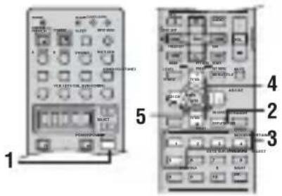
1 Press AMP.


2 Turn on the video monitor and press ON SCREEN repeatedly to select the full display mode.
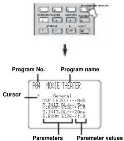
3 Select the sound field program you want to adjust.
4 Press u /d to select the parameters.
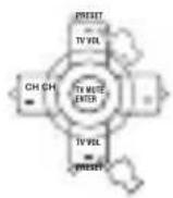
Resetting parameters to the factory presets
To reset all parameters
Use PARAM. INI (see page 65).
5 Press j /i to change the parameter value.
When you set a parameter to a value other than the factory-set value, an asterisk mark (*) appears by the parameter name on the on-screen display.
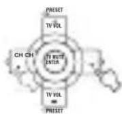
y
If you press and hold / to change the parameter value, the front panel display automatically stops at the factory preset parameter momentarily.
6 Repeat steps 3 through 5 as necessary to change other program parameters.
Note
You cannot change parameter values when "MEMORY GUARD" is set to ON. If you want to change the parameter values, set "MEMORY GUARD" to OFF (see page 64).
Memory back-up
The memory back-up circuit prevents the stored data from being lost even if this unit is set in the standby mode, the power cord is disconnected from the AC outlet, or the power supply is temporarily cut due to power failure. However, if the power is cut for more than one week, the parameter values will return to the factory settings. If this happens, edit the parameter value again.
SOUND FIELD PARAMETER DESCRIPTIONS
You can adjust the values of certain digital sound field parameters so the sound fields are recreated accurately in your listening room. Not all of the following parameters are found in every program.
DSP LEVEL (DSP level)
Function: Adjusts the level of all the DSP effect sounds within a narrow range.
Description: Depending on the acoustics of your listening room, you may want to increase or decrease the DSP effect level relative to the level of the direct sound.
Control range: -6dB to +3dB
■INIT. DLY/P. INIT. DLY (Initial delay)
Function: Changes the apparent distance from the source sound by adjusting the delay between the direct sound and the first reflection heard by the listener.
Description: The smaller the value, the closer the sound source seems to the listener. The larger the value, the farther it seems. For a small room, set to a small value. For a large room, set to a large value.
Control range: 1 to 99 msec
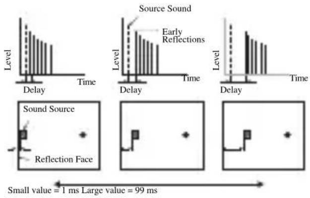
ROOM SIZE/P. ROOM SIZE (Room size)
Function: Adjusts the apparent size of the surround sound field. The larger the value, the larger the surround sound field becomes.
Description: As the sound is repeatedly reflected around a room, the larger the hall is, the longer the time between the original reflected sound and the subsequent reflections. By controlling the time between the reflected sounds, you can change the apparent size of the virtual venue. Changing this parameter from one to two, doubles the apparent length of the room.
Control range: 0.1 to 2.0
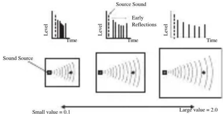
LIVENESS (Liveness)
Function: Adjusts the reflectivity of the virtual walls in the hall by changing the rate at which the early reflections decay.
Description: The early reflections of a sound source decay much faster in a room with acoustically absorbent wall surfaces than in one which has highly reflective surfaces. A room with acoustically absorbent surfaces is referred to as "dead", while a room with highly reflective surfaces is referred to as "live". The LIVENESS parameter lets you adjust the early reflection decay rate, and thus the "liveness" of the room.
Control range: 0 to 10
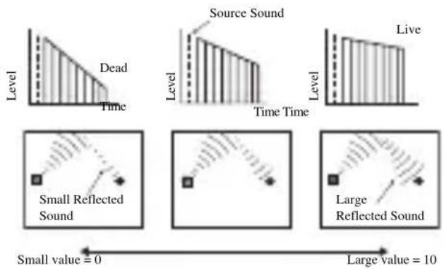
■S. INIT. DLY (Surround initial delay)
Function: Adjusts the delay between the direct sound and the first reflection on the surround side of the sound field. You can only adjust this parameter when at least two front channels and two surround channels are used.
Control Range: 1 to 49 msec
S. ROOM SIZE (Surround room size)
Function: Adjusts the apparent size of the surround sound field.
Control Range: 0.1 to 2.0
S. LIVENESS (Surround liveness)
Function: Adjusts the apparent reflectivity of the virtual walls in the surround sound field.
Control Range: 0 to 10
■SB INI. DLY (Surround back initial delay)
Function: Adjusts the delay between the direct sound and the first reflection in the surround back sound field.
Control Range: 1 to 49 msec
SB ROOM SIZE (Surround back room size)
Function: Adjusts the apparent size of the surround back sound field.
Control Range: 0.1 to 2.0
SB LIVENESS (Surround back liveness)
Function: Adjusts the apparent reflectivity of the virtual wall in the surround back sound field.
Control Range: 0 to 10
■REV.TIME (Reverberation time)
Function: Adjusts the amount of time it takes for the dense, subsequent reverberation sound to decay by 60 dB (at 1kHz ). This changes the apparent size of the acoustic environment over an extremely wide range.
Description: Set a longer reverberation time for "dead" sources and listening room environments, and a shorter time for "live" sources and listening room environments.
Control Range: 1.0 to 5.0 sec
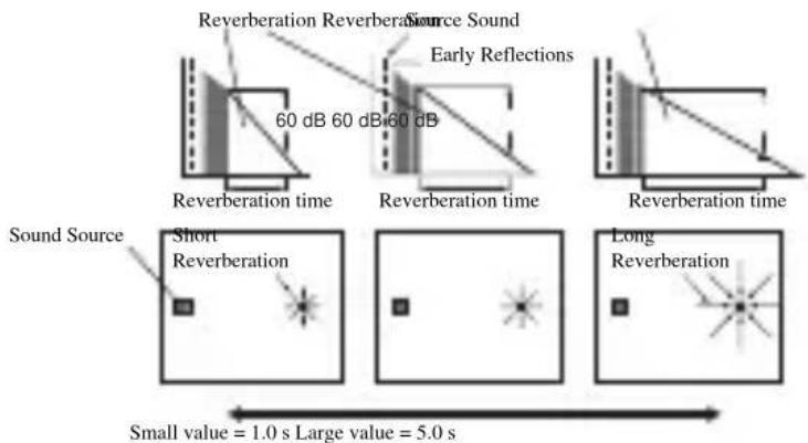
■REV DELAY (Reverberation delay)
Function: Adjusts the time difference between the beginning of the direct sound and the beginning of the reverberation sound.
Description: The larger the value, the later the reverberation sound begins. A later reverberation sound makes you feel like you are in a larger acoustic environment.
Control Range: 0 to 250 msec
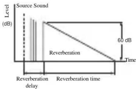
■REV. LEVEL (Reverberation level)
Function: Adjusts the volume of the reverberation sound.
Description: The larger the value, the stronger the reverberation becomes.
Control Range: 0 to 100%
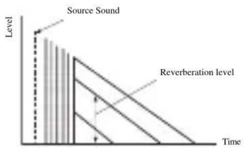
■DIALG.LIFT (Dialog lift)
Function: Adjusts the height of the front and center channel sounds by assigning some of the front and center channel elements to the presence speakers.
Description: The larger the parameter, the higher the position of the front and center channel sound.
Choices: 0/1/2/3/4/5, initial setting is 0.
For 2ch Stereo:
DIRECT (Direct)
Function: Bypasses this unit's decoders and DSP processors for pure high fidelity sound when playing 2-channel analog sources.
Choices: AUTO, OFF
Notes
- When multi-channel signals (Dolby Digital and DTS) are input, they are downmixed to 2 channels and output from the front left and right speakers.
- When "BASS OUT" is set to BOTH, or "FRONT SP" set to SMALL and "BASS OUT" set to SWFR, front left and right speaker low-frequency signals are redirected to the subwoofer.
For 7ch Stereo:
Function: These parameters adjust the volume level for each channel in 7-channel stereo mode.
Control Range: 0 - 100%
CT LEVEL (Center level)
■SL LEVEL (Surround left level)
■SR LEVEL (Surround right level)
SB LEVEL (Surround back level)
PL LEVEL (Presence left level)
■PR LEVEL (Presence level)
For PRO LOGIC IIx Music and PRO LOGIC II Music:
PANorama (Panorama)
Function: Sends stereo signals to the surround speakers as well as the front speakers for a wraparound effect.
Choices: OFF, ON
DIMENSION (Dimension)
Function: Gradually adjusts the sound field either towards the front or towards the rear.
Control range: -3 (towards the rear) to +3 (towards the front), initial setting is STD (standard).
CENTERWIDTH (Center width)
Function: Adjusts the center image from all three front speakers to varying degrees. A larger value adjusts the center image towards the front left and right speakers.
Control range: 0 (center channel sound is output only from center speaker) to 7 (center channel sound is output only from front left and right speakers)
Initial setting: 3
Note
This parameter can be set only when SUR.STANDARD is selected.
For DTS Neo:6 Music:
C. IMAGE (Center image)
Function: Adjusts the center image from all three front speakers to varying degrees. Control range: 0 to 1.0
Initial setting: 0.3
Note
This parameter can be set only when SUR.STANDARD is selected.
TROUBLESHOOTING
Refer to the chart below when this unit does not function properly. If the problem you are experiencing is not listed below or if the instruction below does not help, set this unit to the standby mode, disconnect the power cord, and contact the nearest authorized YAMAHA dealer or service center.
General
| Problem Cause | Remedy | Refer to page | |
| This unit fails to turn on when STANDBY/ON (or SYSTEM POWER) is pressed, or enters the standby mode soon after the power has been turned on. | The power cord is not connected or the plug is not completely inserted. | Connect the power cord firmly. | - |
| The impedance setting is incorrect. Set the impedance to match your speakers. | 67 | ||
| The protection circuitry has been activated. | Make sure all speaker wire connections on this unit and on all speakers are secure and that the wire for each connection does not touch anything other than its respective connection. | 11-14 | |
| This unit has been exposed to a strong external electric shock (such as lightning or strong static electricity). | Set this unit in the standby mode, disconnect the power cord, plug it back in after 30 seconds, then use it normally. | - | |
| On-screen display does not appear. | The setting for the on-screen display is set to “DISPLAY OFF”. | Select the full display or short display mode. | 52 |
| “GRAY BACK” in SET MENU is set to OFF, and no video signal is currently being received. | Set “GRAY BACK” to AUTO to always show the OSD. | 64 | |
| No sound Incorrect input | or output cable connections. | Connect the cables properly. If the problem persists, the cables may be defective. | 15-20 |
| The optimizer microphone is connected. Disconnect the optimizer microphone. | 24 | ||
| The input mode is set to DTS or ANALOG. | Select AUTO. | 37 | |
| No appropriate input source has been selected. | Select an appropriate input source with INPUT, MULTI CH INPUT (or MULTI CH IN on the remote control) or the input selector buttons. | 30 | |
| Speaker connections are not secure. Secure the connections. | 12 | ||
| The front speakers to be used have not been selected properly. | Select the front speakers with SPEAKERS A and/or B. | 30 | |
| The volume is turned down. Turn up the volume. | - | ||
| The sound is muted. Press MUTE or any operation button of this unit to resume audio output, then adjust the volume. | 31 | ||
| The input mode is set to ANALOG while playing a source encoded with a DTS signal. | Set the input mode to AUTO or DTS. | 37 | |
| Signals this unit cannot reproduce are being received from a source component, such as a CD-ROM. | Play a source whose signals can be reproduced by this unit. | - | |
| No picture The output and | input for the picture are connected to different types of video jacks. | Turn on the video conversion function. | 64 |
| The sound suddenly goes off. | The protection circuitry has been act ivated because of a short circuit, etc. | Check that the impedance selector setting is correct. | 67 |
| Check that the speaker wires are not touching each other and then turn this unit back on. | - | ||
| The sleep timer has turned the unit off. Turn on the power, and play the source again. | - | ||
| The sound is muted. Press MUTE to cancel a mute. | 31 | ||
| Only the speaker on one side can be heard. | Incorrect cable connections. Connect the cables properly. If the problem persists, the cables may be defective. | 12 | |
| Incorrect balance settings in SET MENU. Adjust the SPEAKER LEVEL settings. | 59 | ||
| Only the center speaker outputs substantial sound. | When playing a monaural source with a CINEMA DSP program, the source signal is directed to the center channel, and the front and surround speakers output effect sounds. | ||
| No sound from the effect speakers. | The sound field programs are turned off. Press STRAIGHT (EFFECT) to turn them on. | 36 | |
| You are using a source or program combination that does not output sound from all channels. | Try another sound field program. | 49 | |
| No sound from the center speaker. | The output level of the center speaker is set to minimum. | Raise the level of the center speaker. | 59 |
| “CENTER SP” in SET MENU is set to NONE. | Select the appropriate setting for the center speaker. | 57 | |
| One of the HiFi DSP programs (except for 7ch Stereo) has been selected. | Try another sound field program. | 49 | |
| No sound from the surround speakers. | The output level of the surround speakers is set to minimum. | Raise the output level of the surround speakers. | 59 |
| “SUR. L/R SP” in SET MENU is set to NONE. | Select the appropriate setting for the surround left and right speakers. | 57 | |
| A monaural source is being played with STRAIGHT. | Press STRAIGHT (EFFECT) to turn on the sound fields. | - | |
| No sound from the surround back speakers. | Presence speakers are selected. Select surround back speakers in SUR. B L/R SP. | 58 | |
| “SUR. L/R SP” in SET MENU is set to NONE. | If the surround left and right speakers are set to NONE, the surround back speaker setting is automatically set to NONE. Select the appropriate setting for the surround speakers. | 57 | |
| “SUR. B L/R SP” in SET MENU is set to NONE. | Select LRGx1 or SMLx1. | 58 | |
| No sound from the subwoofer. | “LFE/BASS OUT” in SET MENU is set to FRNT when a Dolby Digital or DTS signal is being played. | Select SWFR or BOTH. | 58 |
| “LFE/BASS OUT” in SET MENU is set to SWFR or FRNT when a 2-channel source is being played. | Select BOTH. | 58 | |
| The source does not contain low bass signals. | |||
NOLLWHOENI
VANIOLLAD
| Problem Cause | Remedy | Refer to page | |
| Dolby Digital or DTS sources cannot be played. (Dolby Digital or DTS indicator on the front panel display does not light up.) | The connected component is not set to output Dolby Digital or DTS digital signals. | Make an appropriate setting following the operating instructions for your component. | - |
| The input mode is set to ANALOG. Set the | nput mode to AUTO or DTS. | 37 | |
| A "humming" sound can be heard. | Incorrect cable connections. Firmly connect | he audio plugs. If the problem persists, the cables may be defective. | - |
| No connection from the turntable to the GND terminal. | Connect the grounding cord of your turnable to the GND terminal of this unit. | 19 | |
| The volume level is low while playing a record. | The record is being played on a turntable with an MC cartridge. | The turntable should be connected to this unit through an MC-head amplifier. | 19 |
| The volume level cannot be increased, or the sound is distorted. | The component connected to the OUT (REC) jacks of this unit is turned off. | Turn on the power to the component. | - |
| The sound effect cannot be recorded. | It is not possible to record the sound effect with a recording component. | ||
| A source cannot be recorded by a digital recording component connected to this DIGITAL OUTPUT jack. | The source component is not connected to this unit's DIGITAL INPUT jacks. | Connect the source component to the DIGITAL INPUT jacks. | 15-19 |
| Some components cannot record the Dolby Digital or DTS sources. | |||
| A source cannot be recorded by an analog component connected to the AUDIO OUT jacks. | The source component is not connected to this unit's analog AUDIO IN jacks. | Connect the source component to the analog AUDIO IN jacks. | 15-19 |
| The sound field parameters and some other settings on this unit cannot be changed. | "MEMORY GUARD" in SET MENU is set to ON. | Select OFF. | 64 |
| This unit does not operate properly. | The internal microcomputer has been frozen by an external electric shock (such as lightning or excessive static electricity) or by a power supply with low voltage. | Disconnect the AC power cord from the outlet and then plug it in again after about 30 seconds. | - |
| "CHECK SP WIRES" appears in the front panel display. | Speaker cables are short circuited. Make sure all speaker cables are connected correctly. | 12 | |
| There is noise interference from digital or radio frequency equipment, or this unit. | This unit is too close to the digital or high-frequency equipment. | Move this unit further away from such equipment. | - |
| The picture is disturbed. | The video source uses scrambled or encoded signals to prevent dubbing. | ||
| There is noise when the OSD is displayed. | The OSD may be disturbed when displaying OSD through component video connections. | Select OFF in CMPNT OSD. | 64 |
| This unit suddenly turns into the standby mode. | The internal temperature becomes too high and the overheat protection circuitry has been activated. | Wait about 1 hour for this unit to cool down and then turn it back on. | - |
■Tuner (With the exception of U.K. model)
| Problem Cause Remedy | Refer to page | |||
| FM | FM stereo reception is noisy. | The characteristics of FM stereo broadcasts may cause this problem when the transmitter is too far away or the antenna input is poor. | Check the antenna connections.Try using a high-quality directional FM antenna. | 21 |
| Use the manual tuning method. | 40 | |||
| There is distortion, and clear reception cannot be obtained even with a good FM antenna. | There is multipath interference. Adjust the antenna position to eliminate multipath interference. | — | ||
| The desired station cannot be tuned in with the automatic tuning method. | The signal is too weak. Use a high-quality directional FM antenna. | 21 | ||
| Use the manual tuning method. | 40 | |||
| Previously preset stations can no longer be tuned in. | This unit has been disconnected for a long period. | Preset the stations again. | 40 | |
| AM | The desired station cannot be tuned in with the automatic tuning method. | The signal is weak or the antenna connections are loose. | Tighten the AM loop antenna connections and orient it for the best reception. | — |
| Use the manual tuning method. | 40 | |||
| There are continuous crackling and hissing noises. | Noises result from lightning, fluorescent lamps, motors, thermostats and other electrical equipment. | Use an outdoor antenna and a ground wire.This will help somewhat, but it is difficult to eliminate all noise. | — | |
| There are buzzing and whining noises. | A TV set is being used nearby. Move this unit away from the TV. | — | ||
Remote control
| Problem Cause | Remedy | Refer to page | |
| The remote control does not work nor function properly. | Wrong distance or angle. The remote control | will function within a maximum range of 6 m and no more than 30 degrees off-axis from the front panel. | 7 |
| Direct sunlight or lighting (from an inverter type of fluorescent lamp, etc.) is striking the remote control sensor of this unit. | Reposition this unit. | — | |
| The batteries are weak. Replace all batteries | 3 | ||
| The remote control code was not correctly set. | Set the remote control code correctly. | 69 | |
| Try setting another code for the same manufacturer. | 69 | ||
| The remote control ID and this unit's ID do not match. | Switch the library code. | 67, 69 | |
| Even if the remote control code is correctly set, there are some models that do not respond to the remote control. | Program the necessary functions independently into the programmable buttons using the Learn feature. | 72 | |
| The remote control does not "learn" new functions. | The batteries of this remote control and/or the other remote control are too weak. | Replace the batteries. | 3 |
| The distance between the two remote controls is too much or too little. | Place the remote controls at the proper distance. | 72 | |
| The signal coding or modulation of the other remote control is not compatible with this remote control. | Learning is not possible. | — | |
| Memory capacity is full. Delete other unnecessary functions to make room for the new functions. | 75 |
RESETTING THE FACTORY PRESETS
If you want to reset all of your unit's parameters for any reason, do the following. This procedure completely resets ALL parameters, including the SET MENU, level, assign and tuner presets.
Be sure this unit is in standby mode.
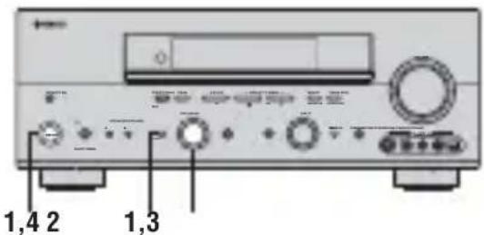
1 With the unit in the standby mode, hold down STRAIGHT (EFFECT) on the front panel and press STANDBY/ON.
The ADVANCED SETUP menu appears in the front panel display.


While holding down, press

To cancel the initialization procedure without making any changes, press STANDBY/ON.
2 Rotate PROGRAM to move through the menu and select "PRESET".

PROGRAM
3 Press STRAIGHT (EFFECT) to select the desired setting.

RESET To reset the unit to its factory presets.
CANCEL To cancel without making any changes.
4 Press STANDBY/ON to confirm your selection.

If you selected "RESET", the unit is reset to its factory presets and switches to standby mode. If you selected "CANCEL", the unit switches to standby mode and nothing is reset.
GLOSSARY
Audio formats
Dolby Digital
Dolby Digital is a digital surround sound system that gives you completely independent multi-channel audio. With 3 front channels (left, center, and right), and 2 surround stereo channels, Dolby Digital provides 5 full-range audio channels. With an additional channel especially for bass effects, called LFE (low frequency effect), the system has a total of 5.1-channels (LFE is counted as 0.1 channel). By using 2-channel stereo for the surround speakers, more accurate moving sound effects and surround sound environment are possible than with Dolby Surround. The wide dynamic range (from maximum to minimum volume) reproduced by the 5 full-range channels and the precise sound orientation generated using digital sound processing provide listeners with previously unheard of excitement and realism.
With this unit, any sound environment from monaural up to a 5.1-channel configuration can be freely selected for your enjoyment.
Dolby Digital EX
Dolby Digital EX creates 6 full-bandwidth output channels from 5.1-channel sources. This is done using a matrix decoder that derives 3 surround channels from the 2 in the original recording. For the best results, Dolby Digital EX should be used with movie sound tracks recorded with Dolby Digital Surround EX. With this additional channel, you can experience more dynamic and realistic moving sound especially with scenes with "flyover" and "fly-around" effects.
Dolby Pro Logic II
Dolby Pro Logic II is an improved technique used to decode vast numbers of existing Dolby Surround software. This new technology enables a discrete 5-channel playback with 2 front left and right channels, 1 center channel, and 2 surround left and right channels (instead of only 1 surround channel for conventional Pro Logic technology). Music and Game modes are also available for 2-channel sources in addition to the Movie mode.
Dolby Pro Logic IIx
Dolby Pro Logic IIx is a new technology enabling discrete multi-channel playback from 2-channel or multi-channel sources. There is a Music mode for music, a Movie mode for movies and a Game mode for games.
Dolby Surround
Dolby Surround uses a 4 channel analog recording system to reproduce realistic and dynamic sound effects: 2 front left and right channels (stereo), a center channel for dialog (monaural), and a surround channel for special sound effects (monaural). The surround channel reproduces sound within a narrow frequency range. Dolby Surround is widely used with nearly all video tapes and laser discs, and in many TV and cable broadcasts as well. The Dolby Pro Logic decoder built into this unit employs a digital signal processing system that automatically stabilizes the volume on each channel to enhance moving sound effects and directionality.
DTS 96/24
DTS 96/24 offers an unprecedented level of audio quality for multi-channel sound on DVD-Video, and is fully backward-compatible with all DTS decoders. "96" refers to a 96kHz sampling rate (compared to the typical 48kHz sampling rate). "24" refers to 24-bit word length. DTS 96/24 offers sound quality transparent to the original 96/24 master, and 96/24 5.1-channel sound with full-quality full-motion video for music programs and motion picture soundtracks on DVD-video.
DTS (Digital Theater Systems) Digital Surround
DTS digital surround was developed to replace the analog soundtracks of movies with a 6-channel digital sound track, and is now rapidly gaining popularity in movie theaters around the world. Digital Theater Systems Inc. has developed a home theater system so that you can enjoy the depth of sound and natural spatial representation of DTS digital surround in your home. This system produces practically distortion-free 6-channel sound (technically, a left, right and center channels, 2 surround channels, plus an LFE 0.1 channel as a subwoofer, for a total of 5.1-channels). The unit incorporates DTS-ES decoder that enables 6.1-channel reproduction by adding the surround back channel to existing 5.1-channel format.
Neo:6
Neo:6 decodes the conventional 2-channel sources for 6 channel playback by the specific decoder. It enables playback with the full-range channels with higher separation just like digital discrete signal playback. Two modes are available: "Music mode" for playing music sources and "Cinema mode" for movies.
Sound field programs Audio information
CINEMA DSP
Since the Dolby Surround and DTS systems were originally designed for use in movie theaters, their effect is best felt in a theater having many speakers and designed for acoustic effects. Since home conditions, such as room size, wall material, number of speakers, and so on, can differ so widely, it's inevitable that there are differences in the sound heard as well. Based on a wealth of actually measured data, YAMAHA CINEMA DSP uses
YAMAHA original sound field technology to combine Dolby Pro Logic, Dolby Digital and DTS systems to provide the visual and audio experience of movie theater in the listening room of your own home.
■SILENT CINEMA
YAMAHA has developed a natural, realistic sound effect DSP algorithm for headphones.
Parameters for headphones have been set for each sound field so that accurate representations of all the sound field programs can be enjoyed on headphones.
■Virtual CINEMA DSP
YAMAHA has developed a Virtual CINEMA DSP algorithm that allows you to enjoy DSP sound field surround effects even without any surround speakers by using virtual surround speakers.
It is even possible to enjoy Virtual CINEMA DSP using a minimal two-speaker system that does not include a center speaker.
■ITU-R
ITU-R is the radio communication sector of the ITU (International Telecommunication Union). ITU-R recommends a standard speaker placement which is used in many critical listening rooms, especially for mastering purposes.
LFE 0.1 channel
This channel is for the reproduction of low bass signals. The frequency range for this channel is 20Hz to 120Hz . This channel is counted as 0.1 because it only enforces a low frequency range compared to the full-range reproduced by the other 5/6 channels in Dolby Digital or DTS 5.1/6.1-channel systems.
PCM (Linear PCM)
Linear PCM is a signal format under which an analog audio signal is digitized, recorded and transmitted without using any compression. This is used as a method of recording CDs and DVD audio. The PCM system uses a technique for sampling the size of the analog signal per very small unit of time. Standing for "pulse code modulation", the analog signal is encoded as pulses and then modulated for recording.
Sampling frequency and number of quantized bits
When digitizing an analog audio signal, the number of times the signal is sampled per second is called the sampling frequency, while the degree of fineness when converting the sound level into a numeric value is called the number of quantized bits.
The range of rates that can be played back is determined based on the sampling rate, while the dynamic range representing the sound level difference is determined by the number of quantized bits. In principle, the higher the sampling frequency, the wider the range of frequencies that can be played back, and the higher the number of quantized bits, the more finely the sound level can be reproduced.
Video signal information
■Component video signal
With the component video signal system, the video signal is separated into the Y signal for the luminance and the B and R signals for the chrominance. Color can be reproduced more faithfully with this system because each of these signals is independent. The component signal is also called the "color difference signal" because the luminance signal is subtracted from the color signal.
A monitor with component input jacks is required in order to use the component signal for output.
Composite video signal
With the composite video signal system, the video signal is composed of three basic elements of a video picture; color, brightness and synchronization data. A composite video jack on a video component transmits these three elements combined.
S-video signal
With the S-video signal system, the video signal normally transmitted using a pin cable is separated and transmitted as the Y signal for the luminance and the C signal for the chrominance through the S-video cable. Using the SVIDEO jack eliminates video signal transmission loss and allows recording and playback of even more beautiful images.
SPECIFICATIONS
AUDIO SECTION
Minimum RMS Output Power for Front, Center, Surround, Surround back 20Hz to 20kHz 0.06% THD, 8 100 W
Maximum Power (EIAJ) [China, Korea and General models] 1 kHz, 10% THD,8Ω 140 W
Dynamic Power (IHF) 8/6/4/2Ω 135/170/200/245 W
DIN Standard Output Power [U.K. and Europe models] 1 kHz, 0.7% THD,4Ω 150 W
- IEC Output Power [U.K. and Europe models] 1 kHz, 0.06% THD, 8Ω 110 W
Damping Factor (IHF) 20 Hz to 20 kHz, 8 Ω 120 or more
Frequency Response CD terminal to Front L/R 10 Hz to 100kHz -3dB
Total Harmonic Distortion PHONO to REC OUT (20Hz to 20kHz,1V) .. 0.02% or less CD, etc. to Front L/R (20Hz to 20kHz,50W,8) . 0.06% or less
- Signal to Noise Ratio (IHF-A Network)
Phono (5 mV) to REC OUT
[U.K., Europe and Australia models] 81 dB or more
[Other models] 86 dB or more
CD (250 mV) to Front L/R, Effect Off 100 dB or more
- Residual Noise (IHF-A Network)
Front L/R 150 V or less
- Channel Separation (1 kHz/10 kHz)
PHONO (shorted) to Front L/R 60 dB/55 dB or more
CD (5.1 kΩ terminated) to Front L/R 60 dB/45 dB or more
- Tone Control (Front L/R)
BASS Boost/Cut ± 6 dB/50 Hz
BASS Turnover Frequency 350Hz TREBLE Boost/Cut ± 6 dB/20 kHz
TREBLE Turnover Frequency 3.5kHz
- Phones Output 150 mV/100 Ω
- Input Sensitivity/Input Impedance
PHONO 2.5 mV/47 kΩ
CD, etc. 200 mV/47 kΩ
MULTI CH INPUT 200 mV/47 kΩ
- Output Level/Output Impedance
REC OUT 200 mV/1.2 kΩ
PRE OUT 2 V/1.2 kΩ
SUBWOOFER 4 V/1.7 kΩ
ZONE 2 OUTPUT
[U.S.A., Canada, Australia and Europe models] 200 mV/1.2 kΩ
VIDEO SECTION
- Video Signal Type PAL/NTSC
- Signal to Noise Ratio 50 dB or more
Frequency Response (MONITOR OUT) Composite, S-video 5 Hz to 10MHz -3dB Component 5 Hz to 60MHz -3dB
FM SECTION*
Tuning Range [U.S.A. and Canada models] 87.5 to 107.9MHz [General model] 87.5/87.50 to 108.0/108.00 MHz [Other models] 87.50 to 108.00MHz
- Usable Sensitivity (IHF) 1.0 μV (11.2 dBf)
- Signal to Noise Ratio (IHF)
Mono/Stereo 76 dB/70 dB
- Harmonic Distortion (1 kHz)
Mono/Stereo 0.2%/0.3%
- Stereo Separation (1 kHz) 42 dB
Frequency Response 20 Hz to 15 kHz, +0.5, -2 dB
AM SECTION*
Tuning Range [U.S.A. and Canada models] 530 to 1710kHz [General model] 530/531 to 1710/1611 kHz [Other models] 531 to 1611kHz
- Usable Sensitivity 300 V/m
GENERAL
Power Supply [U.S.A.and Canada models] AC 120 V,60 Hz [Australia model] AC 240 V,50 Hz [China model] AC 220 V,50 Hz [Korea model] AC 220 V,60 Hz [U.K.and Europe models] AC 230 V,50 Hz [General model] AC 110/120/220/230-240V,50/60 Hz
Power Consumption [U.S.A. and Canada models] 400 W/500 VA [Other models] 440 W
- Standby Power Consumption 0.1 W or less
- A C O u t l e t s [U.K. and Australia models] 1 (Total 100 W maximum) [U.S.A., Canada and China models] ...2 (Total 100 W maximum) [Europe and General models] 2 (Total 50 W maximum)
Dimensions (W× H× D) 435x171x420mm
Weight 12.5 kg
*Except DSP-AX757SE
ATTENTION: VEUILLEZ LIRE CE QUI SUIT AVANT D'UTILISER L'APPAREIL.
Raccordements Zone 2 76
Commande a distance Zone 2. 77
INFORMATIONS COMPLEMENTAIRIES

Piles (4) (AAA, R03, UM-4)

Antenne cadre AM (RX-V757 unquement)
(RX-V757 unquipment)
(RX-V757 unquipment)
(RX-V757 unquipment)
(RX-V757 unquipment)
1 Prises DIGITAL OUTPUT
7 Prise CONTROL OUT (RX-V757 unquipment)
9 Prises DIGITAL INPUT
■EON (Enhanced Other Networks)
Choix: meters (m), feet (ft)
Volume Trim D) VOLUME TRI M
Raccordements Zone 2
DIMENSION (Dimension)
SEHINNEENNNN
SNOLLYWHO-INI
sue
DTS (Digital Theater Systems) Digital Surround
→SP:MINSTDP>HP:MINSTDP>
[]]Up/Down []/Select
Lautsprecher SP
Ton-Bypass TONE BYPASS
2(OPTICALIN(2)),3(OPTICALIN(3))und 4(OPTICALIN(4))
DIMENSION (Dimension)
DTS (Digital Theater Systems) Digital Surround

Batterier (4) (AAA, R03, UM-4)

Optimeringsmikrofon

AM-ramantenn (galler RX-V757)

FM-inomhusantenn (gäller RX-V757)
HÖGTALARINSTALLATION
Högtalarnas placering
SETUP· AUTO START Automatic Processing of top down [C1/C1]:Select
AUTO Utfora autoinstallingsproceduren (YPAO).
- Valj MIN for minimal compression.
- Valj MID for normal compression.
- Valj MAX for maximal compression.
1 Stall in en station.
Se sidan 39 for anvisningar om hur man staller in en station.
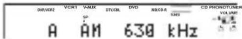
Laget PS (Program Service name)
Namnet pa den radiodatasystem-station som tas emot visas pa displayen.
Laget PTY (Program Type)
■EON (Enhanced Other Networks)
SWFR Niva for subwoofer
Alternative: LRG, SML, NONE
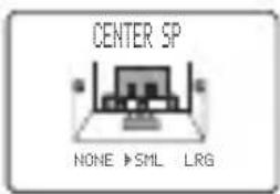
Alternative: LRG, SML, NONE
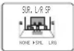
Alternative: meters (m), feet (ft)
Alternative:PHONO, CD, MD/CD-R, TUNER, DVD
DTV/CBL, V-AUX, VCR1, DVR/VCR2
3 OPTION MENU
Anvands for att justera valfria systemparametrar.
■Displayinstallingar A) DI SPLAY SET
Avblandare DI MMER
Alternative: OFF, ON
Alternative: INT,EXT
D)MULTIZONESET
SP B*FRONT ZOHE2 AMP*EXT
1 / 2 :Select ENTER Return
Alternative: 8Ω MIN, 4Ω MIN
Alternative: ID1, ID2
Alternative: OFF, ON
DIMENSION (Dimension)
Funktion: Justerar gradvis ljudfaltet, antingen mot rummet framre del ell er mot dess bakre.
DTS (Digital Theater Systems) Digital Surround
■Sammansatt videosignal
8/6/4/2Ω 135/170/200/245W
1 kHz, 0.7% overtonsdistorsion, 4 Ω 150 W
-
Uteffekt enligt IEC [modeller till Europa, inkl. Storbritannien] 1kHz 0,06% overtonsdistorsion, 8 110 W
-
Dämpningsfaktor (IHF)
20 Hz till 20 kHz, 8 Ω 120 erer mer
- Kanalseparation (1 kHz/10 kHz)
6 REMOTE IN/OUT prese (Solo RX-V757)
cavi video component
Prese analogiche
Cross over CROSS OVER
Opzioni: meters (m), feet (ft)
Usage: this is a general form of the use of the same name.
Usage: this is a general form of the use of the same name.
Tone bypass TONE BYPASS
B (CMPNT-V I NPUT [ B ])
Opzioni: [A] DVD, DTV/CBL, V-AUX, VCR1, DVR/VCR2
[B]DVD, DTV/CBL, V-AUX, VCR1, DVR/VCR2
Per la presa OPTICAL OUTPUT
1(OPTICALOUT(1))
Opzioni:PHONO,CD,MD/CD-R,DVD,DTV/CBL V-AUX,VCR1,DVR/VCR2
Per la presa OPTICAL INPUT
2(OPTICALIN(2)),3(OPTICALIN(3))e
4(OPTICALIN(4))
Opzioni: (2) PHONO, CD, (TUNER*), MD/CD-R, DVD, DTV/CBL, VCR1, DVR/VCR2
(3)PHONO,CD,TUNER*MD/CD-R,DVD
DTV/CBL, VCR1, DVR/VCR2
(4)PHONO,CD,TUNER*MD/CD-R,DVD
DTV/CBL, VCR1, DVR/VCR2
- Solo DSP-AX757SE
Usage: this is a general rule for the use of a particular set of operations in the form of a command.
Usage: this is a general rule for the use of a command to perform a specific operation.
Usage: this is a general rule for the use of a command to perform a specific operation.
B>INPUT MODE
AUTO LAST
(1)[2]:Select ENTER Return
■Note sui software DTS
Gamma di controlo: Da 1,0 a 5,0 sec

Pilas (4)
(AAA, R03, UM-4)
1 Jacks DIGITAL OUTPUT
9 Jacks DIGITAL INPUT
Altavoces surround (SR y SL)
5 Jack SUBWOOFER PRE OUT
Alternatively, you can use the same method to find the number of emisoras in 5 groups, A1 a E8).
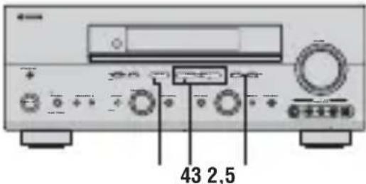
Options: NORMAL, REVERSE
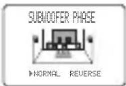
- Selezione NORMAL si no quiere invertir la fase de su altovoz de subgraves.
- Selezione REVERSE para invertir la fase de su altovoz de subgraves.
Opciones: meters (m), feet (ft)
B (CMPNT-V I NPUT [B])
Opiones: [A] DVD, DTV/CBL, V-AUX, VCR1, DVR/VCR2
[B]DVD, DTV/CBL, V-AUX, VCR1, DVR/VCR2
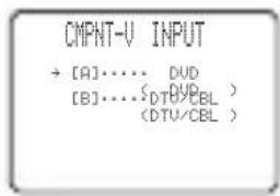
C) I N P U T R E N A M E
S. LIVENESS (Viveza surround)
Margen de control: 1,0 a 5,0 s
■REV DELAY (Retardo de reverberacion)
■DTS (Digital Theater Systems)
Digital Surround
Linker surround DSP geluidsveld

Achter surround DSP geluidsweld
6 CINEMA DSP indicator
Keuzes:LRGx1,LRGx2,SMLx2,SMLx1,NONE
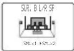
Keuzes: meters (m), feet (ft)
Keuzes: [A] DVD, DTV/CBL, V-AUX, VCR1, DVR/VCR2
[B] DVD, DTV/CBL, V-AUX, VCR1, DVR/VCR2
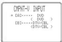
2(OPTICALIN(2),3(OPTICALIN(3))en 4(OPTICALIN(4))
Keuzes: (2) PHONO, CD, (TUNER*), MD/CD-R, DVD, DTV/CBL, VCR1, DVR/VCR2
(3)PHONO,CDTUNER*MD/CD-R,DVD DTV/CBL,VCR1,DVR/VCR2 (4)PHONO,CD(TUNER*),MD/CD-R,DVD
DTV/CBL, VCR1, DVR/VCR2
Volume Trim D) VOLUME TRI M
Keuzes: 8Ω MIN, 4Ω MIN
"MEMORY GUARD" beveiling is ingeschakeld (ON).
S. INIT. DLY (Surround beginvertraging)
■SB INI. DLY (Surround ache ter beginvertraging)
DIALG.LIFT (Dialogo-lift)
■DTS (Digital Theater Systems)
Digital Surround
©2005 All rights reserved.


