
TD 10 - Air Conditioning TECTRO - Free user manual and instructions
Find the device manual for free TD 10 TECTRO in PDF.
| Product type | Air dehumidifier |
| Brand | Tectro |
| Model | TD 10 |
| Dimensions (W x D x H) | 295 x 280 x 440 mm |
| Net weight | 11.5 kg |
| Gross weight | 13.0 kg |
| Power supply voltage | 220-240 V, 50 Hz, 1 Ph |
| Power consumption | 0.22 kW |
| Current draw | 1.6 A |
| Dehumidification capacity | 10 L/24h (at 32°C, 80% RH) |
| Water tank capacity | 1.1 L |
| Recommended room volume | 40 to 60 m³ |
| Operating temperature | 5 to 32 °C |
| Auto defrost | Yes |
| Adjustable hygrostat | Yes (from Normal to Max) |
| Compressor type | Piston |
| Refrigerant | R134A, 160 g |
| Noise level | 40 dB(A) |
| Protection rating | IP20 |
| Fuse | 250 V, T6.3 A |
| Continuous drainage | Possible (hose ø 13 mm) |
| Air filter | Washable, clean every 2 weeks |
| Warranty | 2 years |
Frequently Asked Questions - TD 10 TECTRO
User questions about TD 10 TECTRO
0 question about this device. Answer the ones you know or ask your own.
Ask a new question about this device
Download the instructions for your Air Conditioning in PDF format for free! Find your manual TD 10 - TECTRO and take your electronic device back in hand. On this page are published all the documents necessary for the use of your device. TD 10 by TECTRO.
USER MANUAL TD 10 TECTRO

HAUPTBAUTEILE
natural_image
Technical line drawing of a portable air conditioner unit (no text or symbols)
VIGTIGE DELE
natural_image
Line drawing of a portable air conditioner unit with ventilation slots and lid (no text or symbols)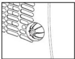
natural_image
Simple line drawing of a basketball with ribbons (no text or symbols)
COMPONENTES PRINCIPALES
natural_image
Line drawing of a portable air conditioner unit with ventilation slots and lid (no text or symbols)
PIÈCES PRINCIPALES
natural_image
Technical line drawing of a mechanical device with internal components and mounting brackets (no text or symbols)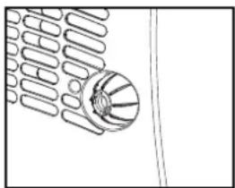
natural_image
Pure technical line drawing of a mechanical component without any text, numbers, or symbolsL'ÉVACUATION DE L'EAU

TÄRKEÄT OSAT
natural_image
Line drawing of a mechanical device with internal components and mounting brackets (no text or symbols)Congratulations with the purchase of your dehumidifier. You have acquired a high quality product which will give you many years of pleasure, if you use it responsibly. Please read the user's manual first in order to ensure the optimum life span of your dehumidifier. On behalf of the manufacturer, we provide a two-year warranty on material- or manufacturing defects.
Enjoy your dehumidifier.
Yours sincerely,
PVG International B.V.
Customer Service Department
1 PLEASE READ THE USER'S MANUAL FIRST.
2 IF YOU HAVE ANY DOUBTS, CONSULT YOUR DEALER.

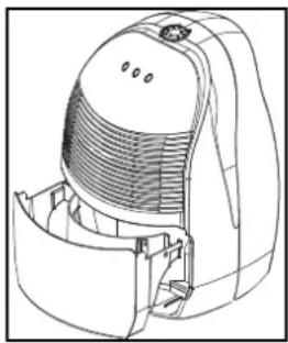
IMPORTANT COMPONENTS
① Control panel
② Adjustment button/hydrostat
③ Dry air outlet
4 Removable water container
⑤ Humid air inlet
6 Air filter
⑦ Drain spout
(ø13 mm) with cap
8 Plug and cord
9 Handle
SAFETY INSTRUCTIONS
Install the device only when it complies with local regulations, by-laws and standards. The unit is only suitable for use in dry locations, indoors. Check the mains voltage and frequency. This unit is only suitable for earthed sockets, connection voltage 220-240 V. / 50 Hz.
GENERAL
- To obtain optimum performance from your dehumidifier, do not place it near a radiator or any other heat source.
- Ensure that all windows are closed in order to achieve maximum efficiency.
- The capacity of the dehumidifier depends on the temperature and the humidity in the room. At lower temperatures, less moisture will be removed.
- Ensure that the screen filter is kept clean. This prevents unnecessary power consumption and guarantees optimum efficiency.
- If the power supply has been interrupted, the defumidifier will restart after three minutes. The automatic delay protects the compressor.

IMPORTANT
The device MUST always have an earthed connection. If the power supply is not earthed, you may not connect the unit. The plug must always be easily accessible when the unit is connected. Read these instructions carefully and follow the instructions.
Before connecting the unit, check the following:
- The voltage supply must correspond with the mains voltage stated on the rating label.
- The socket and power supply must be suitable for the current stated on the rating label.
- The plug on the cable of the device must fit into the wall socket.
- The device must be placed on a flat and stable surface.
The electricity supply to the device must be checked by a recognised professional if you have any doubts regarding the compatibility.
- This device is manufactured according to CE safety standards. Nevertheless, you must take care, as with any other electrical device.
- Do not cover the air inlet and outlet grill.
• Empty the water reservoir before moving the unit. - Never allow the device to come into contact with chemicals.
- Never spray the unit with or submerge in water
- Do not insert objects into the openings of the unit.
- Always remove the plug from the electric power supply before cleaning or replacing the unit or components of the unit.
-
Never use an extension cable to connect the device to the electric power supply. If there is no suitable, earthed wall socket available, have one installed by a recognised electrician.
-
For safety reasons take care when children are in the surrounding of the device, as with any other electrical device.
- Have any repairs only carried out by a recognised service engineer or your supplier. Follow the instructions for use and maintenance as indicated in the user manual of this device.
• Always remove the plug of the unit from the wall socket when it is not in use. - A damaged power cord or plug must always be replaced by a recognised electrician or your supplier.

ATTENTION!
- Never use the device with a damaged power cord, plug, cabinet or control panel. Never trap the power cord or allow it to come into contact with sharp edges.
- Failing to follow the instructions may lead to nullification of the guarantee on this device.
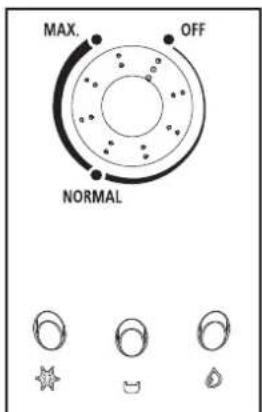
CONTROL LIGHTS ON THE CONTROL PANEL

This light indicates that the defrost function has been activated. This is necessary to prevent excessive formation of ice in the device.

This light indicates that the water container is full. The device switches off automatically.

The device is in operation when this light is on.
OPERATION
1 Ensure that the hydrostat is in the OFF position before inserting the plug into the wall outlet.
2 Ensure that the water container has been positioned correctly. If the light switches on when you use the device for the first time, remove the water container from the device and replace it in the correct position.
3 Turn the hydrostat to the desired position. The hydrostat is continuously adjustable. Set the hydrostat to 'NORMAL', which produces a relative humidity of approximately 50% and provides a comfortable living environment.
The device starts to dehumidify when the relative humidity in the room is higher than the set value.
The device switches off automatically when the set value is reached, and restarts when the humidity in the room rises again.
Setting the hydrostat to the 'MAX.' position keeps the device in continuous operation.

Turn the adjustment button to the 'OFF' position to turn the device off.
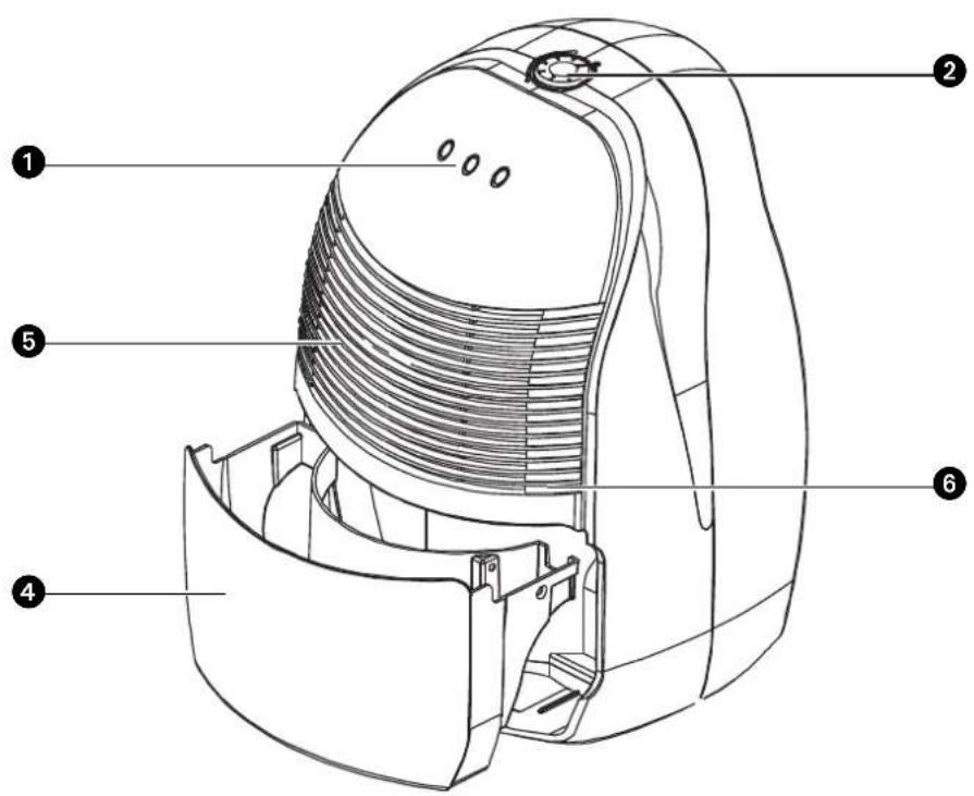
WATER DRAINAGE
natural_image
Line drawing of a mechanical device with a circular top and internal fan-like structure (no text or symbols)When the water container is full, the light switches on and the dehumidifier switches off automatically. Empty the container and replace it in the correct position. The device will restart.
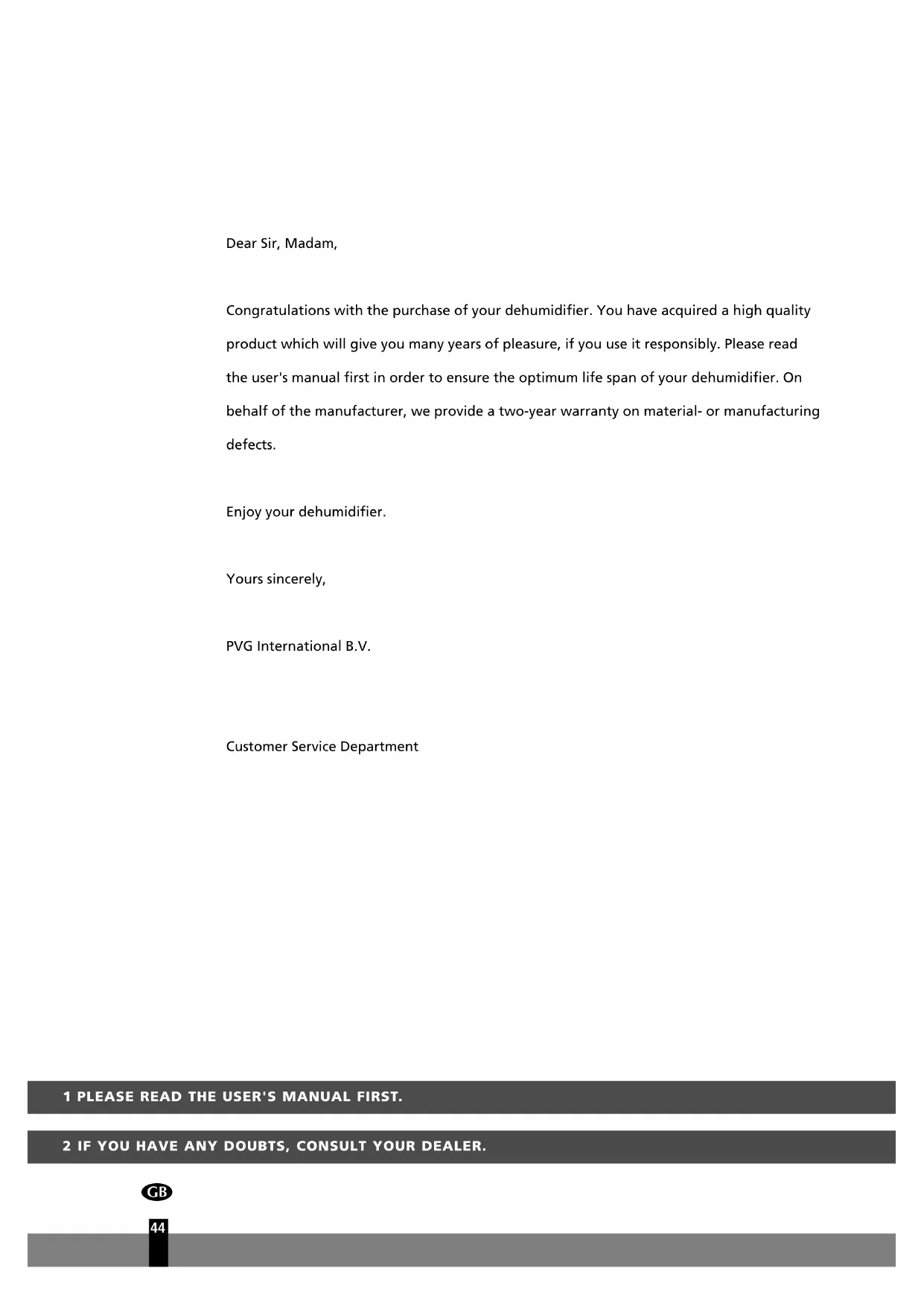
If desired, it is possible to connect a drainage hose to the device for permanent water drainage. Follow these steps:

natural_image
Simple line drawing of a basketball hoop with ribbons (no text or symbols)1 Unscrew the cap on the back.
2 Remove the rubber stop from the drainage spout.
3 Connect the drainage hose and ensure that the end of the hose is lower than the spout, otherwise the water will not drain and flooding may occur.
4 Place the end of the drainage hose in a water outlet.
When you no longer wish to use the permanent water drainage, disconnect the drainage hose from the device. Push the rubber stop back into the drainage spout and replace the cap. Ensure that the water container is positioned correctly.
CLEANING
Switch the dehumidifier off and remove the plug from the socket before cleaning.
THE EXTERIOR
Clean the exterior with a soft, dry cloth. If the device is extremely dirty, use a mild cleaning agent. Wipe the device with a slightly damp cloth. Never spray the device with water.
THE AIR FILTER
When used regularly, the filter may become clogged with dust and particles. Therefore the filter should be cleaned every two weeks. Follow these steps:
1 Remove the water container from the device. Tilt the device backwards a little and remove the filter.
2 Clean the filter with a vacuum cleaner or with water. Dry the filter and replace it. Ensure that the filter is completely dry. Replace the water container.

Never use the device without the air filter.
STORAGE
If the machine will not be used for a long period of time, take the following steps:
1 Remove the plug from the socket and empty the container. Allow the container and the dehumidifier to dry completely.
2 Clean the air filter.
3 Store the device in a dust-free location, preferably covered with a sheet of plastic.
TROUBLE SHOOTING
Check the following before contacting technical support:
| Problem Cause Solution | ||
| The unit does not work. | The powercord is not connected. | Insert the plug into the wall outlet. |
| The hydrostat setting is too low. | Turn the hydrostat to the desired setting. | |
| The water container is full. | Remove the water from the container. | |
| The water container has not been replaced correctly. | Place the water container in the correct position. | |
| The device does not dehumidify. | The air filter is clogged. Clean the air filter. | |
| The temperature or relative humidity in the room where the device is operating is too low. | It is normal that the device does not dehumidify in these conditions. | |
| The dehumidifier works, but reduces the relative humidity insufficiently. | The room is too large. | We recommend using a dehumidifier with a greater capacity. |
| There are too many sources of humidity. | We recommend using a dehumidifier with a greater capacity. | |
| There is too much ventilation. | Reduce ventilation (e.g. close curtains and shut doors). | |
CONDITIONS OF WARRANTY
There is a two-year warranty on your dehumidifier from the date of purchase. All material or manufacturing defects will be repaired free of charge.
The following applies:
- All claims for compensation, including consequential damage, will not be entertained.
- Any repairs or replacement of components during the warranty period will not result in an extension of the warranty period.
- The warranty will expire if any alterations have been made, not genuine components have been fitted or if the dehumidifier has been repaired by a third party.
- Components subject to normal wear and tear, such as the air filter, are not covered by the warranty.
- The warranty is only valid on presentation of the original, unaltered, and date-stamped purchase receipt.
- The warranty does not cover damage caused by actions that deviate from those as described in the user's manual or by neglect.
- Transportation costs and the risks involved during the transportation of the dehumidifier or components shall always be for the account of the purchaser.
To prevent unnecessary expenses, we recommend that you always carefully read the user's manual first. If this does not provide a solution, take the dehumidifier to your distributor for repair.
Waste electrical products should not be disposed with household waste. Please recycle where facilities exist. Check with your local authority or retailer for recycling advice.
Environmental information: This equipment contains fluorinated greenhouse gases covered by the Kyoto Protocol. It should only be serviced or dismantled by professional trained personnel.
This equipment contains R134a refrigerant in the amount as stated in the table above. Do not vent R134a into atmosphere: R134a, is a fluorinated greenhouse gas with a Global Warming Potential (GWP) = 1300
TECHNICAL SPECIFICATIONS
| Model TD 10 | ||
| Power consumption kW | 0.22 | |
| Power supply V / Hz / Ph | 220-240 / 50 / 1 | |
| Current (nom.) A | 1.6 | |
| Dehumidifying capacity* L / 24h 10 | ||
| Capacity water container | L | 1.1 |
| Air flow (nom.)** | m^3/h | 100 |
| For rooms up to** | m^3 | 40 - 60 |
| Operating range | °C | 5-32 |
| Automatic defrost | Y | |
| Hydrostat | Y | |
| Compressor type | Piston | |
| Refrigerant type / charge | r / gr | R134A / 160 |
| Dimensions (w x d x h ) | mm | 295 x 280 x 440 |
| Net weight | kg | 11.5 |
| Gross weight | kg | 13.0 |
| Sound pressure level | dB(A) | 40 |
| Unit Protection | IP | IP 20 |
| Fuse rating | 250V, T6.3A | |
* Moisture removal at 32°C, 80%RH
** To be used as indication
Subject to change without prior notice.
PERFORMANCE GRAPH
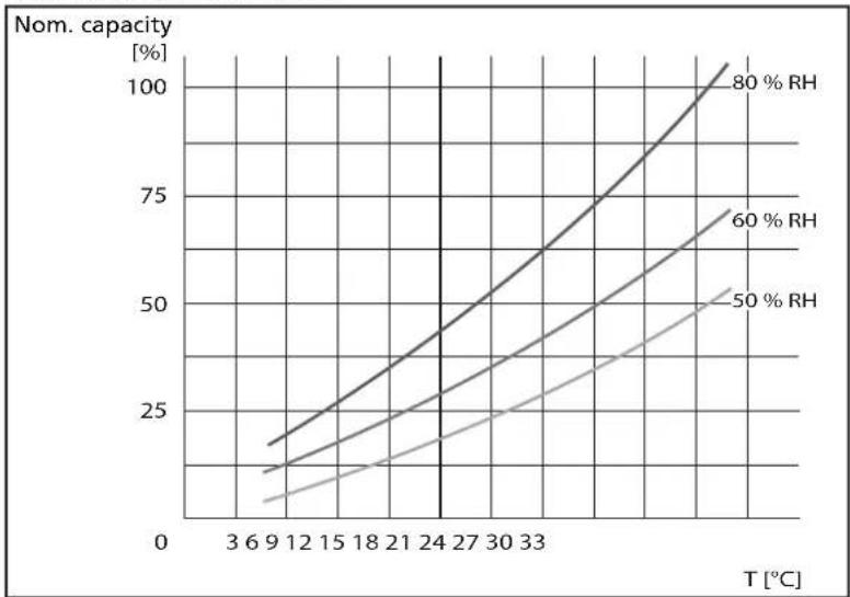
(to be used as indication only)
Egregio signore, gentile signora,

COMPONENTI PRINCIPALI
natural_image
Technical line drawing of a mechanical device with ventilation slots and a fan (no text or symbols)
natural_image
Pure technical line drawing of a mechanical component without any text, numbers, or symbols
VIKTIGE DELER
natural_image
Line drawing of a mechanical device with internal components and mounting brackets (no text or symbols)
BELANGRIJKE ONDERDELEN
natural_image
Technical line drawing of a mechanical device with ventilation slots and a lid (no text or symbols)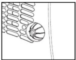
natural_image
Pure technical line drawing of a mechanical component without any text, numbers, or symbols
natural_image
Technical line drawing of a mechanical device with internal components and mounting brackets (no text or symbols)natural_image
Simple line drawing of a basketball hoop with ribbons (no text or symbols)Czyszczenie
line
| T [°C] | 50 % RH | 60 % RH | 80 % RH | | ------ | ------- | ------- | ------- | | 3 | ~5 | ~10 | ~15 | | 9 | ~10 | ~15 | ~20 | | 12 | ~15 | ~20 | ~25 | | 15 | ~20 | ~25 | ~30 | | 18 | ~25 | ~30 | ~35 | | 21 | ~30 | ~35 | ~40 | | 24 | ~35 | ~40 | ~45 | | 27 | ~40 | ~45 | ~50 | | 30 | ~45 | ~50 | ~55 | | 33 | ~50 | ~55 | ~60 | | 36 | ~55 | ~60 | ~65 | | 39 | ~60 | ~65 | ~70 | | 42 | ~65 | ~70 | ~75 | | 45 | ~70 | ~75 | ~80 | | 48 | ~75 | ~80 | ~85 | | 51 | ~80 | ~85 | ~90 | | 54 | ~85 | ~90 | ~95 | | 57 | ~90 | ~95 | ~100 | | 60 | ~95 | ~100 | ~105 | | 63 | ~100 | ~105 | ~110 | | 66 | ~105 | ~110 | ~115 | | 69 | ~110 | ~115 | ~120 | | 72 | ~115 | ~120 | ~125 | | 75 | ~120 | ~125 | ~130 | | 78 | ~125 | ~130 | ~135 | | 81 | ~130 | ~135 | ~140 | | 84 | ~135 | ~140 | ~145 | | 87 | ~140 | ~145 | ~150 | | 90 | ~145 | ~150 | ~155 | | 93 | ~150 | ~155 | ~160 | | 96 | ~155 | ~160 | ~165 | | 99 | ~160 | ~165 | ~170 | | 102 | ~165 | ~170 | ~175 | | 105 | ~170 | ~175 | ~180 | | 108 | ~175 | ~180 | ~185 | | 111 | ~180 | ~185 | ~190 | | 114 | ~185 | ~190 | ~195 | | 117 | ~190 | ~195 | ~200 | | 120 | ~195 | ~200 | ~205 | | 123 | ~200 | ~205 | ~210 | | 126 | ~205 | ~210 | ~215 | | 129 | ~210 | ~215 | ~220 | | 132 | ~215 | ~220 | ~225 | | 135 | ~220 | ~225 | ~230 | | 138 | ~225 | ~230 | ~235 | | 141 | ~230 | ~235 | ~240 | | 144 | ~235 | ~240 | ~245 | | 147 | ~240 | ~245 | ~250 | | 150 | ~245 | ~250 | ~255 | | 153 | ~250 | ~255 | ~260 | | 156 | ~255 | ~260 | ~265 | | 159 | ~260 | ~265 | ~270 | | 162 | ~265 | ~270 | ~275 | | 165 | ~270 | ~275 | ~280 | | 168 | ~275 | ~280 | ~285 | | 171 | ~280 | ~285 | ~290 | | 174 | ~285 | ~290 | ~295 | | 177 | ~290 | ~295 | ~300 | | 180 | ~295 | ~300 | ~305 | | 183 | ~300 | ~305 | ~310 | | 186 | ~305 | ~310 | ~315 | | 189 | ~310 | ~315 | ~320 | | 192 | ~315 | ~320 | ~325 | | 195 | ~320 | ~325 | ~330 | | 198 | ~325 | ~330 | ~335 | | 201 | ~330 | ~335 | ~340 | | 204 | ~335 | ~340 | ~345 | | 207 | ~340 | ~345 | ~350 | | 210 | ~345 | ~350 | ~355 | | 213 | ~350 | ~355 | ~360 | | 216 | ~355 | ~360 | ~365 | | 219 | ~360 | ~365 | ~370 | | 222 | ~365 | ~370 | ~375 | | 225 | ~370 | ~375 | ~380 | | 228 | ~375 | ~380 | ~385 | | 231 | ~380 | ~385 | ~390 | | 234 | ~385 | ~390 | ~395 | | 237 | ~390 | ~395 | >400 | | 240* | >40* >49*| >49* >48*| >48* >47*| | 244* (with label) T = - T = - T = - T = - T = - T = - T = - T = - T = - T = - T = - T = - T = - T = - T = - T = - T = - T = - T = - T = - T = - T = - T = - T = - T = - T = - T = - T = - T = - T = - T = - T = - T = - T = - T = - T = - T = - T = - T = - T = - T = - T = - T = - T = - T = - T = - T = - T = - T = - T = - T = - T = - T = - T = - T = - T = - T = - T = - T = - T = - T = - T = - T = - T = - T = - T = - T = - T = - T = - T = - T = - T = - T = - T = - T = - T = - T = - T = - T = - T = - T = - T = - T = - T = - T = - T = - T = - T = - T = - T = - T = - T = - T = - T = - T = - T = - T = - T = - T = - T = (T < .->) (T < .->) (T < .->) (T < .->) (T < .->) (T < .->) (T < .->) (T < .->) (T < .->) (T < .->) (T < .->) (T < .->) (T < .->) (T < .->) (T < .->) ( ) (T < .->) (T < .->) (T < .->) (T < .->) (T < .->) ( ) (T < .->) (T < .->) (T < .->) ( ) (T < .->) ( ) (T < .->) ( ) ( ) ( ) ( ) ( ) ( ) ( ) ( ) ( ) ( ) ( ) ( ) ( ) ( ) ( ) ( ) ( ) ( ) ( ) ( ) ( ) ( ) ( ) ( ) ( ) ( ) ( ) ( ) ( ) ( ) ( ) ( ) ( ) ( ) ( ) ( ) ( ) ( ) ( ) ( ) ( ) ( ) ( ) ( ) ( ) ( ) ( ) ( ) ( ) ( ) ( ) nan nan nan nan nan nan nan nan nan nan nan nan nan nan nan nan nan nan nan nan nan nan nan nan nan nan nan nan nan nan nan nan nan nan nan nan nan nan nan nan nan nan nan nan nan nan nan nan nan nan nan nan nan nan nan nan nan nan nan nan nan nan nan nan nan nan nan nan nan nan nan nan nan nan nan nan nan nan nan nan nan nan nan nan nan nan nan nan nan nan nan nan nan nan nan nan nan nan nan nan nan / / / / / / / / / / / / / / / / / / / / / / / / / / / / / / / / / / / / / / / / / / / / / / / / / / / / / / / / / / / / / / / / / / / / / / / / / / / / / / / / / / / / / / / / / / / / / / / / / / / / / A: A: A: A: A: A: A: A: A: A: A: A: A: A: A: A: A: A: A: A: A: A: A: A: A: A: A: A: A: A: A: A: A: A: B: B: B: B: B: B: B: B: B: B: B: B: B: B: B: B: B: B: B: B: B: B: B: B: B: B: B: B: B: B: B: B: B: B: C: C: C: C: C: C: C: C: C: C: C: C: C: C: C: C: C: C: C: C: C: C: C: C: C: C: C: C: C: C: C: C: C: C/ D D D D D D D D D D D D D D D D D D D D D D D D D D D D D D D D D D D D D D D D D D D D D D D D D D D F F F F F F F F F F F F F F F F F F F F F F F F F F F F F F F F F F F F F F F F F F F F F F F F F F F G G G G G G G G G G G G G G G G G G G G G G G G G G G G G G G G G G G G G G G G G G G G G G G G G G G H H H H H H H H H H H H H H H H H H H H H H H H H H H H H H H H H H H H H H H H H H H H H H H H H H I J K L M N O P Q R S S U V W X Y Z AA AB AC AD AE AF AG AH AI AJ AK AL AM AN AO AP AQ AR AS AS AZ BA BA BA BA BA BA BA BA BA BA BA BA BA BA BA BA BA BA BA BA BA BA BA BA BA BA BA BA BA BA BA BA BA BA BA BA BA BA BA BA BA BA BA BA BA BA BA BA BA BA BB BB BB BB BB BB BB BB BB BB BB BB BB BB BB BB BB BB BB BB BB BB BB BB BB BB BB BB BB BB BB BB BB BB BB BB BB BB BB BB BB BB BB BB BB BB BB BB BB BB BB BB BB BB BB BB BB BB BB BB BB BB BB BB BB BB BB BB BB BB BB BB BB BB BB BB BB BB BB BB BB BB BB BB BB BB AB AB AB AB AB AB AB AB AB AB AB AB AB AB AB AB AB AB AB AB AB AB AB AB AB AB AB AB AB AB AB AB AB AB AB AB AB AB AB AB AB AB AB AB AB AB AB AB AB AB AB AB AB AB AB AB AB AB AB AB AB AB AB AB AB AB AB AB AB AB AB AB AB AB AB AB AB AB AB AB AB AB AB AB AB AB AB AB AB AB AB AB AB AB AB AB AB AB AB AB AB DB DB DB DB DB DB DB DB DB DB DB DB DB DB DB DB DB DB DB DB DB DB DB DB DB DB DB DB DB DB DB DB DB DB DB DB DB DB DB DB DB DB DB DB DB DB DB DB DB DB DB Trend for each category is normalized to nominal levels of nominal securities. The chart displays a line graph with x-axis labeled 'Temperature' and y-axis labeled 'Nominalnej możliwości', where each line represents a distinct nominal level. The data points are plotted for each category. The chart is saved as a PNG file named 'Nominalnej możliwości_uzrądzzenia' and is displayed in CSV format as shown above. The table is saved as a PNG file named 'Nominalnej możliwości_uzrądzzenia' and is displayed in CSV format as shown below. The data series include four lines representing nominal levels of nominal securities. The values are calculated based on the nominal level of nominal securities and are presented in separate columns. However, the data series does not have explicit numerical labels or units specified in the code. Therefore, the chart is not possible to extract specific values from the original table. However, the text in the chart is provided in the required format. However, the data series can be extracted directly from the image. However, the text in the chart is not possible to extract specific values from the original table. However, the data series can be extracted directly from the image. However, the text in the chart is not possible to extract specific values from the original table. However, the data series can be extracted directly from the image. However, the text in the chart is not possible to extract specific values from the original table. However, the data series can be extracted directly from the image. However, the text in the chart is not possible to extract specific values from the original table. However, there is no additional data series present in this view. However, the text in the chart is not possible to extract specific values from the original table. However, there is no additional data series present in this view. However, the text in the chart is not possible to extract specific values from the original table. However, there is no additional data series present in this view. However, there is no additional data series present in this view. However, there is no additional data series present in this view. However, there is no additional data series present in this view. However, there is no additional data series present in this view. However, there is no additional data series present in this view. However, there is no additional data series present in this view. However, there is no additional data series present in this view. However, there is no additional data Series present in this view. However, there is no additional data Series present in this view. However, there is no additional data Series present in this view. However, there is no additional data Series present in this view. However, there is no additional data Series present in this view. However, there is no additional data Series present in this view. However, there is no additional data Series present in this view. However, there is no additional data Series present in this view. However, there are no additional data Series present in this view. However, there are no additional data Series present in this view. However, there are no additional data Series present in this view. However, there are no additional data Series present in this view. However, there are no additional data Series present in this view. However, there are no additional data Series present in this view. However, there are no additional data Series present in this view. However, there are no additional data Series present in this view.(wartości średnie)

VIKTIGA KOMPONENTER
natural_image
Line drawing of a mechanical device with internal components and mounting brackets (no text or symbols)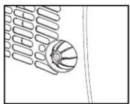
natural_image
Pure technical line drawing of a mechanical component without any text, numbers, or symbols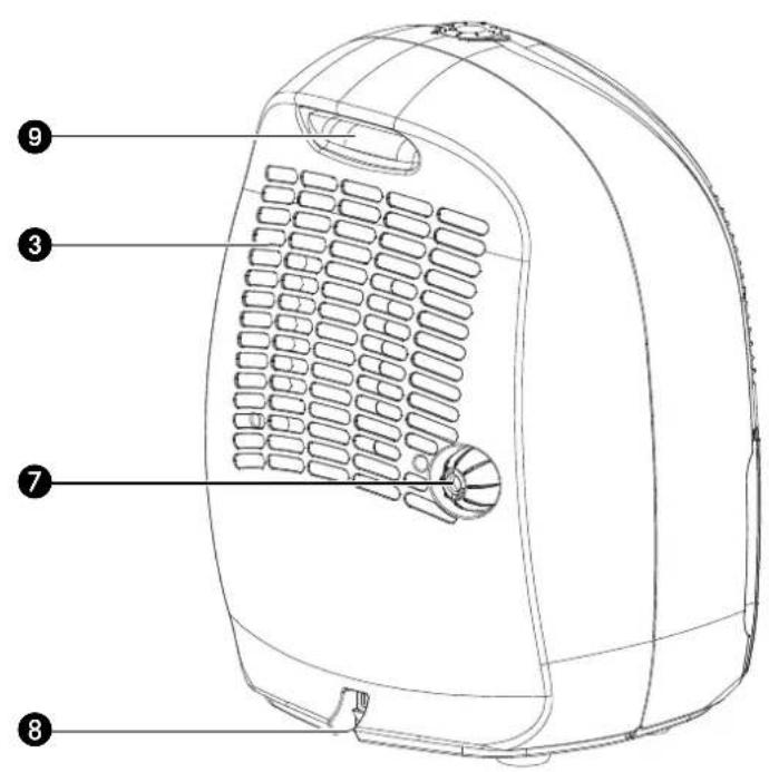
POMEMBNI SESTAVNI DELI
natural_image
Line drawing of a mechanical device with internal components and mounting brackets (no text or symbols)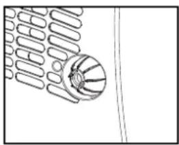
natural_image
Simple line drawing of a basketball hoop with ribbons (no text or symbols)Environmental information: This equipment contains fluorinated greenhouse gases covered by the Kyoto Protocol. It should only be serviced or dismantled by professional trained personnel.
This equipment contains R134a refrigerant in the amount as stated in the table above. Do not vent R134a into atmosphere: R134a, is a fluorinated greenhouse gas with a Global Warming Potential (GWP) = 1300
TEHNIČNI OPIS
| Model | TD 10 | |
| Poraba energije kW | 0.22 | |
| Proizvodnja električne energije V / Hz / Ph | 220-240 / 50 / 1 | |
| Tok (nom.) A | 1.6 | |
| Zmogljivost razvlaževajna* L / 24h | 10 | |
| Kapaciteta posode za vodo L | 1.0 | |
| Pretok zraka(nom.)** | m3/h | 100 |
| Za prostore do ** | m3 | 40 - 60 |
| Obseg delovanja | °C | 5-32 |
| Avtomatsko odmrzovanje | Y | |
| Hidrostat | Y | |
| Model kompresorja | Piston | |
| Hladilni model / obremenitev r / gr | R134A / 200 gr | |
| Dimenzije (š x g x v) mm | 295 x 280 x 440 | |
| Neto teža | kg | 11.5 |
| Bruto teža | kg | 13.0 |
| Stopnja hrupa | dB | 40 |
| Zavarovanje naprave | IP | IP 20 |

ANA PARÇALAR
natural_image
Technical line drawing of a mechanical device with internal components and mounting brackets (no text or symbols)natural_image
Pure technical line drawing of a mechanical component without any text, numbers, or symbolsTEMIZLIK
email: appliance@appliance-group.com
E ESP AÑA
PVG España S.A.
Pol. Ind. San José de Valderas II
email: appliance@appliance-group.com
GB UNITED KINGDOM
Scott Brothers Ltd.
The Old Barn, Holly House Estate
Cranage, Middlewich, CW10 9LT UK
tel.: +44 1606 837787
fax: +44 1606 837757
email: sales@scottmail.co.uk
ITALIA
PVG Italy SRL
Via Niccolò Copernico 5
50051 CASTELFIORENTINO (FI)
tel: +39 0 571 628 500
fax: +39 0 571 628 504
email: pvgitaly@zibro.com
N NORGE
Appliance Norge AS
Vogellunden 31
1394 NESBRU
tel: +47 667 76 200
fax: +47 667 76 201
email: appliance@appliance-group.com
NL NEDERLAND
PVG International B.V.
P.O. Box 96
5340 AB OSS
tel: +31 412 694 694
fax: +31 412 622 893
email: pvgnl@zibro.com
PORTUGAL
Gardena, Lda
email: appliance@appliance-group.com
TIR TURKEY

- HAUPTBAUTEILE
- VIGTIGE DELE
- COMPONENTES PRINCIPALES
- PIÈCES PRINCIPALES
- L'ÉVACUATION DE L'EAU
- TÄRKEÄT OSAT
- IMPORTANT COMPONENTS
- SAFETY INSTRUCTIONS
- GENERAL
- IMPORTANT
- ATTENTION!
- CONTROL LIGHTS ON THE CONTROL PANEL
- OPERATION
- WATER DRAINAGE
- CLEANING
- THE EXTERIOR
- THE AIR FILTER
- STORAGE
- TROUBLE SHOOTING
- CONDITIONS OF WARRANTY
- The following applies:
- TECHNICAL SPECIFICATIONS
- COMPONENTI PRINCIPALI
- VIKTIGE DELER
- BELANGRIJKE ONDERDELEN
- Czyszczenie
- VIKTIGA KOMPONENTER
- POMEMBNI SESTAVNI DELI
- ANA PARÇALAR
- TEMIZLIK
- E ESP AÑA
- GB UNITED KINGDOM
- ITALIA
- N NORGE
- NL NEDERLAND
- PORTUGAL
- TIR TURKEY
Brand : TECTRO
Model : TD 10
Category : Air Conditioning