
TPX 32 - Air Conditioning TECTRO - Free user manual and instructions
Find the device manual for free TPX 32 TECTRO in PDF.
| Product type | Mobile split air conditioner |
| Brand | Tectro |
| Model | TPX 32 |
| Cooling capacity | 3200 W (EN14511 standard) |
| Energy class | D |
| EER | 2.6 |
| Nominal power consumption | 1200 W / 6.1 A |
| Power supply | 220-240 V ~ 50 Hz |
| Indoor unit dimensions (W×D×H) | 530 × 360 × 900 mm |
| Outdoor unit dimensions (W×D×H) | 440 × 300 × 480 mm |
| Indoor unit weight | 36 kg |
| Outdoor unit weight | 13 kg |
| Max dehumidification | 48 L/24h (at 32°C, 80% RH) |
| Max indoor airflow | 450 m³/h |
| Max room size | 100 m³ |
| Thermostat range | 16 °C to 32 °C |
| Indoor/outdoor noise level | 58 dB / 60 dB |
| Refrigerant | R407C / 660 g |
| Compressor type | Rotary |
| Fan speeds | 3 (high, medium, low) |
| Flexible hose length | 2.5 m |
| Indoor/outdoor protection class | IP20 / IP24 |
| Functions | Cooling, dehumidification, air circulation, timer (1-12h) |
| Filters | Screen filter (washable) + activated carbon filter (replaceable) |
| Water drainage | Pumping to outdoor unit; indoor tank 0.5 L with automatic shut-off |
| Safety | Auto shut-off when tank full, compressor overheat protection (3 min), grounded plug required |
| Warranty | 24 months (excluding wear parts such as filters) |
| Supplied accessories | Remote control (not mentioned but assumed), safety straps, mounting rails, wrenches, screws, wall plugs, protective caps, connection for door/window frame |
Frequently Asked Questions - TPX 32 TECTRO
User questions about TPX 32 TECTRO
0 question about this device. Answer the ones you know or ask your own.
Ask a new question about this device
Download the instructions for your Air Conditioning in PDF format for free! Find your manual TPX 32 - TECTRO and take your electronic device back in hand. On this page are published all the documents necessary for the use of your device. TPX 32 by TECTRO.
USER MANUAL TPX 32 TECTRO
natural_image
Abstract black-and-white graphic with diagonal lines and a central white shape (no text or symbols)A
natural_image
Abstract geometric line drawing with intersecting curves and a central symbol (no text or labels)B
C
natural_image
Simple line drawing of a double door frame with diagonal lines and a shaded bottom panel (no text or symbols)D

E

natural_image
Symbolic illustration of a campfire crossing over a fire, enclosed in a square frame with diagonal lines (no text or symbols)F
natural_image
Black silhouette of a faucet with water droplets falling, crossed by diagonal lines (no text or symbols)G
natural_image
Cross-shaped diagram with a container pouring liquid into a block, no text or symbols present.H
natural_image
Hand holding a pen over a grid-patterned rectangle (no text or symbols)|
natural_image
Pure electrical circuit lines without any symbolsJ
natural_image
Black and white pictogram showing a dog and a cat crossed out by diagonal lines (no text or symbols)K
natural_image
Abstract geometric pattern with black and gray shapes intersected by diagonal lines (no text or symbols)L
GBGENERAL SAFETY
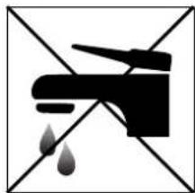
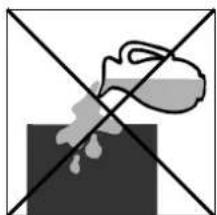
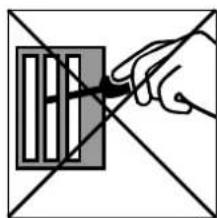
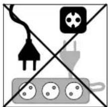
For safety reasons, please read this manual carefully before operating. Persons who are not familiar with this manual must not use this air conditioner. We strongly recommend keeping this manual in a safe place for future reference.
| A. Do not use a damaged cable. | G. Do not immerse in water. |
| B. Do not clamp or bend the cable. | H. Do not spill. |
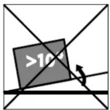
| C Do not place unevenly. | I. Do not insert anything. |
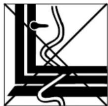
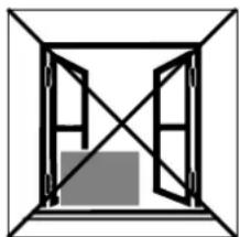
| D. Do not place in front of an open window. | J. Do not use an extension cord. |
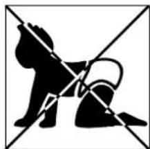
| E. Do not bring in contact with chemicals. | K. Keep out of the reach of children. |
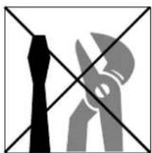
| F. Do not place near a heat source. | L. Do not repair. |
SICUREZZA
15 Schraubenschlüssel


-
LESEN SIE ZUERST DIE GEBRAUCHSANWEISUNG.
-
WENDEN SIE SICH IM ZWEIFELSFALL AN IHREN HÄNDLER.
D
natural_image
Line drawing of a portable air conditioner unit next to a door (no text or symbols)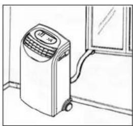
natural_image
Line drawing of an air conditioner unit next to a window (no text or symbols)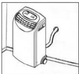
natural_image
Line drawing of a small air conditioner unit with control panel and scroll (no text or symbols)natural_image
Hand-drawn sketch of a mechanical device with a magnified inset showing a detail of a bracket and handle (no text or symbols)INSTALLATION DES AUßENGERÄTS
natural_image
Symbol of a trash bin crossed out by diagonal lines, representing waste sorting or anti-smoking (no text present)


-
LÆS F∅RST BETJENINGSVEJLEDNINGEN
-
I TVIVLSTILFÆLDE HENVEND DEM TIL DERES FORHANDLER
DK
Kære kunde,
natural_image
Illustration of a hand holding a laptop next to a wall-mounted device (no text or symbols visible)INSTALLATION AF DEN EKSTERNE ENHED
T∅MNING AF VANDBEHOLDER
TILSLUTNING
natural_image
Symbol of a trash bin crossed with no text or labels


-
LEA PRIMERO EL MANUAL DEL USUARIO.
-
EN CASO DE DUDA, CONSULTE A SU DISTRIBUIDOR.
Estimado/a señor/a:
natural_image
Hand-drawn sketch of a mechanical device with a magnified inset showing a bracket detail (no text or symbols)natural_image
Symbol of a trash bin crossed with no text or labelsPIÈCES PRINCIPALES


-
LISEZ PRÉALABLEMENT LE MANUEL D'UTILISATION.
-
EN CAS DE DOUTE, CONTACTEZ VOTRE REVENDEUR.
Madame, Monsieur,
natural_image
Line drawing of a portable air conditioner unit next to a door (no text or symbols)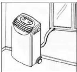
natural_image
Line drawing of an air conditioner unit next to a window (no text or symbols)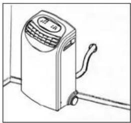
natural_image
Line drawing of a portable air conditioner unit with control panel and scroll (no text or symbols)K CONDITIONS DE GARANTIE
natural_image
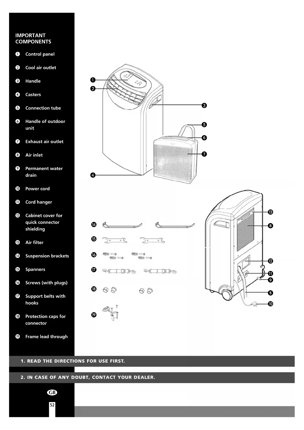
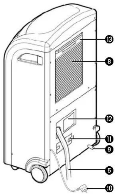
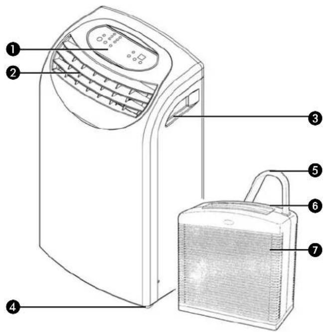
Symbol of a trash bin crossed out by two diagonal lines (no text or labels)IMPORTANT COMPONENTS
① Control panel
② Cool air outlet
3 Handle
4 Casters
5 Connection tube
6 Handle of outdoor unit
⑦ Exhaust air outlet
8 Air inlet
⑨ Permanent water drain
10 Power cord
⑪ Cord hanger
⑫ Cabinet cover for quick connector shielding
13 Air filter
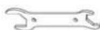
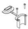
14 Suspension brackets
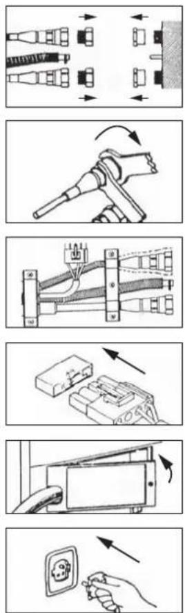
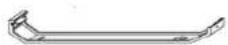
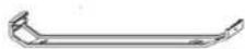
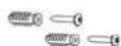
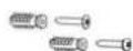
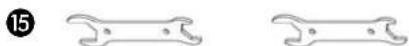
15 Spanners
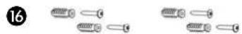
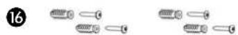
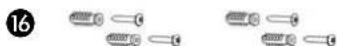
16 Screws (with plugs)
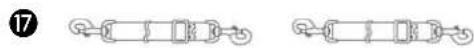
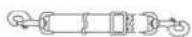
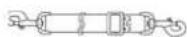
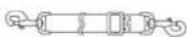
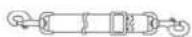
⑰ Support belts with hooks
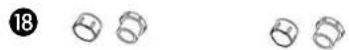
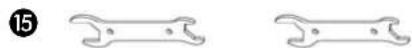
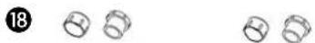
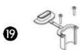
18 Protection caps for connector
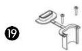
19 Frame lead through
14
15

16

17
18


19


-
READ THE DIRECTIONS FOR USE FIRST.
-
IN CASE OF ANY DOUBT, CONTACT YOUR DEALER.
GB
Dear Sir, Madam,
Congratulations on the purchase of your air conditioner. In addition to air cooling, this air conditioner has two other functions, namely air dehumidification and circulation.
The mobile air conditioner is extremely easy to operate and move. You have acquired a high quality product that will provide you with many years of pleasure, on condition that you use it responsibly. Reading these instructions for use before operating your air conditioner will optimise its life span. We wish you coolness and comfort with your air conditioner.
Yours sincerely,
PVG International B.V.
Customer service department
A SAFETY INSTRUCTIONS
Install the device only when it complies with local regulations, by-laws and standards. The unit is only suitable for use in dry locations, indoors. Check the mains voltage and frequency. This unit is only suitable for earthed sockets, connection voltage 220-240 V. / 50 Hz.

IMPORTANT
The device MUST always have an earthed connection. If the power supply is not earthed, you may not connect the unit. The plug must always be easily accessible when the unit is connected. Read these instructions carefully and follow the instructions.
Before connecting the unit, check the following:
- The voltage supply must correspond with the mains voltage stated on the rating label.
- The socket and power supply must be suitable for the current stated on the rating label.
- The plug on the cable of the device must fit into the wall socket.
- The device must be placed on a flat and stable surface.
The electricity supply to the device must be checked by a recognised professional if you have any doubts regarding the compatibility.
- This device is manufactured according to CE safety standards. Nevertheless, you must take care, as with any other electrical device.
- Do not cover the air inlet and outlet grill.
- Empty the water reservoir before moving the unit.
- Never allow the device to come into contact with chemicals.
- Never spray the unit with or submerge in water
- Do not insert objects into the openings of the unit.
- Always remove the plug from the electric power supply before cleaning or replacing the unit or components of the unit.
- Never use an extension cable to connect the device to the electric power supply. If there is no suitable, earthed wall socket available, have one installed by a recognised electrician.
- For safety reasons take care when children are in the surrounding of the device, as with any other electrical device.
- Have any repairs only carried out by a recognised service engineer or your supplier. Follow the instructions for use and maintenance as indicated in the user manual of this device.
- Always remove the plug of the unit from the wall socket when it is not in use.
- A damaged power cord or plug must always be replaced by a recognised electrician or your supplier.

ATTENTION!
- Never use the device with a damaged power cord, plug, cabinet or control panel. Never trap the power cord or allow it to come into contact with sharp edges.
- Failing to follow the instructions may lead to nullification of the guarantee on this device.
B INSTALLATION
The indoor and outdoor unit are portable and can easily be moved from one room to another. They are connected to each other by a 2.5 metre flexible tube. The outdoor unit can be placed on the floor (of a balcony) or hung on a wall. When handling the units, take the following into account:
1 Ensure that the units are positioned upright and on a level surface.
2 Do not operate the unit inside the bathroom, shower, or in any other humid environment.
3 Please keep a distance of at least 50 cm between the indoor unit and the wall or other objects to ensure proper air circulation.
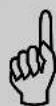
4 Please keep a distance of at least 5 cm between the outdoor unit air inlet and wall or other objects and a distance of at least 120 cm between the outdoor unit exhaust air outlet and wall or other objects to ensure proper air circulation.
5 The maximum distance from the top of the outdoor unit to the floor is 1.5 m.
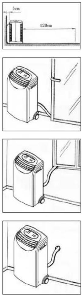
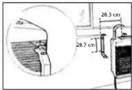
6 To avoid damaging the connection tube, leave the window ajar. The frame lead through 19 can be used to prevent this.
7 Close the window or door as much as possible to prevent outside air from entering the room.

WARNING
Ensure a good air flow through the units. The exhaust air must flow freely. Any blockage can lead to damage or improper operation of the air conditioner.
Take care to prevent any bow or bend in the connection tube.
natural_image
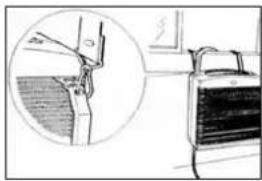
Simple line drawing of a cabinet with an open door, showing a close-up of the cabinet handle (no text or symbols)INSTALLATION OF THE OUTDOOR UNIT
1 Firmly screw the mounting bracket ⑭ to the wall.
2 Connect the safety belts to the outdoor unit and a fixed object inside the room in order to avoid danger when accidentally dropping the outdoor unit.
3 Hang the outdoor unit.

IMPORTANT
The condensation water must flow freely. Blockage of the drainage tube can result in water leakage or improper operation of the unit.
C OPERATION
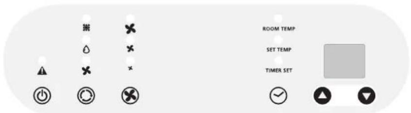
1 Insert the plug into the wall outlet.
2 Press the button to switch on the air conditioner.
3 With Ⓞ button you can change the operating mode of the unit. By pressing the Ⓞ button the following modes appear:
Cooling, the green light lits.
Dehumidifying, the orange light lits.
Air circulation, the yellow light lits.
COOLING
When the unit is in the cooling mode, the following functions apply:
- The fan speed can be adjusted by pressing the -button
Maximum setting.
Medium setting.
✗ Lowest setting.
- The temperature can be set by pressing the and buttons, anywhere between 16°C en 32°C. The display will show the set temperature for 15 seconds and the "set temp" will light up. Fifteen seconds after setting the required temperature, the display will show the room temperature.
It depends on the environment whether the required temperature will be reached. It is not a malfunction of the air conditioner if the room temperature remains above the “set temp”.
When the unit is in the dehumidifying mode, the fan speed cannot be adjusted. The fanspeed will be automatically set on 'Medium setting'. The buttons and can also not be adjusted.
The water which is extracted from the air is pumped to the outdoor unit through the connection tube. Ensure that the water has a free flow outside and it is not cause of any danger or inconvenience.
AIR CIRCULATION
In this mode the unit only circulates air; the unit will not cool or dehumidify. The air entering the unit is not cooled or dehumidified, but is filtered.
When the unit is in this mode, the following functions apply:
- The fan speed can be adjusted by pressing the -button
Maximum setting.
× Medium setting.
✗ Lowest setting.
4 When the unit is switched off the most recent setting will be stored in memory.
5 The timer function allows you to switch the unit on or off at a certain time.
TO SWITCH ON THE UNIT AT A CERTAIN TIME
- Ensure that the unit is set in the required operating mode
- Switch off the unit by pressing the -button. Ensure that the plug is properly inserted into the wall outlet.
- Press the -button. The light "Timer set" will flash.
- Use the and buttons to set a time between 1 and 12 hours.
- When the set time has expired the unit will switch on.
TO SWITCH OFF THE UNIT AT A CERTAIN TIME
- When the unit is operating in the required mode press the -button. The light "Timer set" will flash.
- Use the and buttons to set a time between 1 and 12 hours.
- When the set time has expired the unit will switch off.

NOTE!
The compressor has been set so that it starts functioning three minutes after the (re)start of the air conditioner.
The cooling will switch off when the room temperature is lower than the set one. Air circulation will however continue to work on the set level. When the room temperature rises above the selected value, the cooling will work again.
D AIR FILTER
The air conditioner is fitted with a 2-layer filter to purify the circulating air.
- Screen filter – to remove larger dust particles.
- Active carbon filter – to remove odours.
The filter holder at the back of the indoor unit can be opened. The active carbon filter can then be removed. The screen filter is a part of the filter holder.
1 The screen filter must be cleaned regularly with a vacuum cleaner in order to prevent blockage of the air flow.
2 If it has become dusty, the active carbon filter can be cleaned with a vacuum cleaner. For an optimum result, we recommend that you replace this filter regularly.

COMMENT
- Never use the unit without the screen filter!
- New active carbon filters are available from your dealer.
- Using the unit without the active carbon filter will not damage the air conditioner.
E AIR FLOW
Move the indoor unit to change the air flow direction.
F DRAINAGE
Under normal conditions the condensation water is pumped to the outdoor unit through the connection tube. When the water flow is blocked or the position of the outdoor unit is too high, water may accumulate in the indoor water container of the unit.
When the internal water container is full the light will flash and the unit will beep continuously. The unit will switch off automatically.
TO EMPTY THE WATER CONTAINER DO THE FOLLOWING
1 Do not move the unit. Drastic movements can cause water leakage.
2 Switch off the unit and remove the plug from the wall outlet.
3 Place a pan or appropriate tray on the floor underneath the permanent drain tube.
4 Remove the rubber plug from the drain tube and let the water run out. (± 0.5 litres).
5 Replace the rubber plug, put the plug into the wall outlet, and switch on the unit. The warning light should be off.
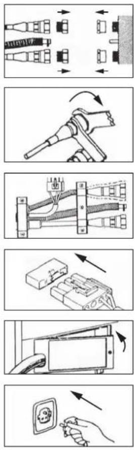
G (DIS)CONNECTING THE INDOOR AND OUTDOOR UNIT (FOR QUALIFIED PERSONNEL)
DISCONNECTING
1 Switch off the unit, remove the plug from the mains and leave it idle for at least 30 minutes.
2 Open the cabinet cover for quick connector shielding 12.
3 Disconnect the electric cable.
4 Disconnect the drain tube.
5 Remove the metal brackets which are holding the tubes and wire.
6 Remove the isolation material from the connectors.
7 Disconnect the refrigerant tubes using the spanners 15 provided. The terminals are fitted with automatic self-sealing valves to prevent the refrigerant from leaking. Loosen the nuts quickly, so the seal is made promptly. During the operation take extreme care not to break or bend the refrigerant tubes.
8 Screw the protection caps for the connectors 18 onto the ends of the refrigerant tubes connectors.
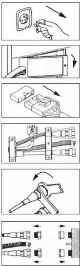

CONNECTING
1 Pass the connection tube through the hole (at least 50 mm) in the wall.
2 Remove the protection caps from the ends of the refrigerant tubes.
3 Reconnect the refrigerant tubes according to the marking (tighten the nuts quickly to make a good seal), the drain tube and the electrical cable.
4 Put the isolation material around the connectors / tubing again.
5 Put back the metal brackets which are holding the tubes and wire.
6 Close the cabinet cover for quick connector shielding ⑫.
7 Store the protection caps 18 in a safe place.
WARNING
After connecting the refrigerant tubes, take care that these are well isolated again. If this is not done properly, damage because of condensation water can occur!
H CLEANING

WARNING!
Switch off the unit and remove the plug from the mains before cleaning the appliance or filter, or before replacing the filters.
Clean the housing with a soft, damp cloth. Never use aggressive chemicals, petrol, detergents or other cleansing solutions. For maintenance of the filters, refer to Chapter D "Air Filter".
NOTE!
Never use the air conditioner without screenfilter.
| STORAGE
1 Empty the internal water container (refer to Chapter F)
2 Clean and replace the screen filter (see also chapter D).
3 Put the unit in air circulation mode for a couple of hours to ensure that the inside becomes completely dry.
4 Store the power cable in the appropriate place, protect the unit against dust and store in a dry place not accessible to children.
J TROUBLE SHOOTING
| Problem Cause | Solution | |
| The unit does not function | No power supply | Connect to a functioning outlet and switch on |
| Water tank indicator is on ⚠️ | Empty the internal water container (refer to Chapter F) | |
| The unit does not seem to perform | In direct sunlight Close curtains | |
| Windows or doors open, many people or heat source in room | Close doors and windows, or place an extra air conditioner | |
| Dirty filter Clean or replace filter | ||
| Air inlet or air outlet blocked Remove blockage | ||
| Room temperature lower than selected value | Change temperature selection | |
| The unit is noisy | Unit stands uneven | Place on even surface (less vibrations) |
| The compressor does not work | Overheat protection probably activated | Wait 3 minutes until the temperature has decreased, and turn on the unit again |
Never try to repair or dismantle the air conditioner yourself. Incompetent repairs result in loss of warranty and can endanger the user.
K GUARANTEE CONDITIONS
The air conditioner is supplied with a 24-month guarantee, commencing on the date of purchase. All material and manufacturing defects will be repaired or replaced free of charge within this period. The following rules apply:
- We expressly refuse all further damage claims, including claims for collateral damage.
- Repairs to or replacement of components within the guarantee period will not result in an extension of the guarantee.
- The guarantee is invalidated if any modifications have been made, non genuine parts are fitted or repairs are carried out by third parties.
- Components subject to normal wear, such as the filter, are not covered by the guarantee.
- The guarantee is valid only when you present the original, dated purchase invoice and if no modifications have been made.
- The guarantee is invalid for damage caused by neglect or by actions that deviate from those in this instruction booklet.
- Transportation costs and the risks involved during the transportation of the air conditioner or air conditioner components shall always be for the account of the purchaser.
- Refrigerant loss and/or leakage because of incompetent (dis)connecting the units is not covered by the guarantee conditions applicable to this product.
To prevent unnecessary expense, we recommend that you always first carefully consult the instructions for use. Take the air conditioner to your dealer for repairs if these instructions do not provide a solution.
L TECHNICAL DATA
| Model | TPX 32 | |
| Cooling capacity* W 3200 | ||
| EE Class* | D | |
| EER* | 2.6 | |
| Power consumption W 1200 | ||
| Current nom. A 6.1 | ||
| Mains V/Hz/PH 220 – 240 / 50 / 1 | ||
| Air delivery max. (indoor unit) | m^3/h | 450 |
| Dehumidification max. ** | L/24h | 48 |
| Room size | m^3 | 100 |
| Refrigerant type/gr R407C / 660 | ||
| Thermostat range °C 16 - 32 | ||
| Noise level indoor unit dB | 58 | |
| Noise level outdoor unit | dB | 60 |
| Dimensions indoor unit (W x D x H) | mm | 530 x 360 x 900 |
| Dimensions outdoor unit (W x D x H) | mm | 440 x 300 x 480 |
| Weight indoor unit | kg | 36 |
| Weight outdoor unit | kg | 13 |
| Compressor type | Rotary | |
| Fan speeds | 3 | |
| Length connection tube | m | 2.5 |
| Unit protection indoor unit | IP 20 | |
| Unit protection outdoor unit | IP 24 | |
* Conform EN 14511
** Moisture removal at 32°C, 80% RH
Waste electrical products should not be disposed with household waste. Please recycle where facilities exist. Check with your local authority or retailer for recycling advice.
natural_image
Symbol of a trash bin crossed with no text or labelsELENCO PARTI
14


15

16


17

18


19

- LEGGERE DAPPRIMA LE ISTRUZIONI D'USO.
- IN CASO DI DUBBIO, RIVOLGERSI AL RIVENDITORE.
natural_image
Line drawing of a portable air conditioner unit next to a door (no text or symbols)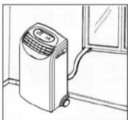
natural_image
Line drawing of an air conditioner unit next to a window (no text or symbols)
natural_image
Line drawing of a portable air conditioner unit with control panel and scroll (no text or symbols)natural_image
Illustration of a car hood with a magnified inset showing the handle and seat (no text or symbols)
ATTENZIONE
J GUIDA ALLA RICERCA GUASTI
natural_image
Symbol of a trash bin with crossed lines indicating no waste or discharge (no text or labels)BELANGRIJKE ONDERDELEN
① Bedieningspaneel
② Luchtuitblaasrooster
③ Handgreep
4 Wielen
⑤ Verbindingsslang
6 Handgreep
⑦ Luchtafvoer
14


15


16

17

18


19


natural_image
Hand-drawn sketch of a car interior with a magnified inset showing hand positioning and roof structure (no text or symbols)INSTALLATIE BUITENUNIT
KOPPELEN
natural_image
Symbol of a trash bin with crossed lines indicating no waste or restriction (no text or labels)ISTOTNE CZEŚCI


-
PRZED PIERWSZYM UŻYCIEM PRZECZYTAĆ INSTRUKCJE OBSŁUGI.
-
W RAZIE WATPLIWOŚCI SKONTAKTOWAĆ SIE, Z DEALEREM.
Szanowni Państwo,
natural_image
Line drawing of a portable air conditioner unit next to a door (no text or symbols)natural_image
Line drawing of a car interior with a magnified inset showing hand positioning and structural details (no text or symbols)Chłodzenie
natural_image
Symbol of a trash bin crossed out by two diagonal lines (no text or numbers present)DISTRIBUTED IN EUROPE BY PVG INTERNATIONAL B.V.
A ÖSTERREICH
Holloway Bank, Wednesbury
West Midlands WS10 OAW
Tel.: +44 121 506 1818
Fax: +44 121 505 1744
email: gases@lister.co.uk
ITALIA
PVG Italy SRL
Via Niccolò Copernico 5
50051 CASTELFIORENTINO (FI)
tel: +39 571 628500
fax: +39 571 628504
email: pvgitaly@zibro.com
N NORGE
Sunwind - Gylling A/S
Rudsletta 71-75 / P.O. Box 64
N-1309 RUD
tel: +47 67 17 13 70
fax: +47 67 17 13 80
email: pvgint@zibro.com
NL NEDERLAND
PVG International B.V.
P.O.Box 96
5340 AB OSS
tel: +31 412 694694
fax: +31 412 622893
email: pvgnl@zibro.com
PORTUGAL
Gardena, Lda

- GBGENERAL SAFETY
- SICUREZZA
- INSTALLATION DES AUßENGERÄTS
- INSTALLATION AF DEN EKSTERNE ENHED
- T∅MNING AF VANDBEHOLDER
- TILSLUTNING
- PIÈCES PRINCIPALES
- K CONDITIONS DE GARANTIE
- IMPORTANT COMPONENTS
- A SAFETY INSTRUCTIONS
- IMPORTANT
- ATTENTION!
- B INSTALLATION
- WARNING
- INSTALLATION OF THE OUTDOOR UNIT
- C OPERATION
- COOLING
- AIR CIRCULATION
- TO SWITCH ON THE UNIT AT A CERTAIN TIME
- TO SWITCH OFF THE UNIT AT A CERTAIN TIME
- NOTE!
- D AIR FILTER
- COMMENT
- E AIR FLOW
- F DRAINAGE
- TO EMPTY THE WATER CONTAINER DO THE FOLLOWING
- G (DIS)CONNECTING THE INDOOR AND OUTDOOR UNIT (FOR QUALIFIED PERSONNEL)
- DISCONNECTING
- CONNECTING
- H CLEANING
- WARNING!
- | STORAGE
- J TROUBLE SHOOTING
- K GUARANTEE CONDITIONS
- L TECHNICAL DATA
- ELENCO PARTI
- ATTENZIONE
- J GUIDA ALLA RICERCA GUASTI
- BELANGRIJKE ONDERDELEN
- INSTALLATIE BUITENUNIT
- KOPPELEN
- ISTOTNE CZEŚCI
- Chłodzenie
- DISTRIBUTED IN EUROPE BY PVG INTERNATIONAL B.V.
- A ÖSTERREICH
- ITALIA
- N NORGE
- NL NEDERLAND
- PORTUGAL
Brand : TECTRO
Model : TPX 32
Category : Air Conditioning