
42HQV035 - Air Conditioning CARRIER - Free user manual and instructions
Find the device manual for free 42HQV035 CARRIER in PDF.
| Product type | Wall-mounted split air conditioner |
| Brand | Carrier |
| Model | 42HQV035 |
| Refrigerant | R410A (HFC) |
| Power supply | 220-240 V ~ 50/60 Hz, single phase |
| Maximum current | 11 A |
| Fuse rating | 25 A |
| Max pipe length | 15 m (model 38VYX035) |
| Max allowable height difference | 10 m |
| Indoor unit dimensions (approx.) | Height: 170 mm, Width: 800 mm, Depth: 200 mm (estimate) |
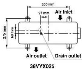
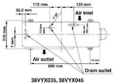
| Outdoor unit dimensions (38VYX035) | 600 mm × 600 mm × 275 mm (W×D×H) |
| Pipe insulation material | Polyethylene foam, thickness 6 mm |
| Power cable type | H07RN-F or 245 IEC66, cross-section ≥1.5 mm² |
| Available functions | Test mode (Cool), auto restart |
| Recommended maintenance | Regular cleaning of air filters |
| Safety | Installation by qualified personnel, power cut before work, mandatory earthing |
| Repairability | Intervention only by Carrier approved technician |
| Supplied spare parts | Refrigerant pipe, insulation material, putty, PVC tape, installation plate |
| General information | Compliant with EMC Directive 89/336/EEC, requires notification to electricity supplier |
Frequently Asked Questions - 42HQV035 CARRIER
User questions about 42HQV035 CARRIER
0 question about this device. Answer the ones you know or ask your own.
Ask a new question about this device
Download the instructions for your Air Conditioning in PDF format for free! Find your manual 42HQV035 - CARRIER and take your electronic device back in hand. On this page are published all the documents necessary for the use of your device. 42HQV035 by CARRIER.
USER MANUAL 42HQV035 CARRIER
MANUEL D'INSTALLATION
INSTALLATIONSHANDBOK
ASENNUSOPAS
INSTALLASJONSVEILEDNING
AIR CONDITIONER (SPLIT TYPE)
LUFTKONDITIONERINGSAPPARAT (I SPLITUTFÖRANDE)
ILMASTOINTILAITE (SPLIT-MALLI)
KILMAANLEGGET (DELT TYPE)
42HQV025
42HQV035
42HQV045
Indoor Unit
Unidad Interior
Unité Intérieure
Unità Interna
Innengerät
Unidade Interior
Εσωτερική Μονάδα
PRECAUTIONS FOR SAFETY .... 1
INSTALLATION DIAGRAM OF INDOOR AND OUTDOOR UNITS 2
- Optional Installation Parts .... 2
INDOOR UNIT
- Installation Place .... 3
- Cutting a Hole and Mounting Installation Plate .... 3
• Electrical Work 4
- Wiring Connection 4
- Piping and Drain Hose Installation .... 5
- Indoor Unit Fixing 6
- Drainage 6
OUTDOOR UNIT
- Installation Place 6
- Refrigerant Piping Connection .... 7
• Evacuating 7 - Wiring Connection 8
OTHERS
• Gas Leak Test 8
- Test Operation 8
• Auto Restart Setting 8
CONTENIDOS
PRECAUCIONES SOBRE SEGURIDAD .... 1
INSTALLATIESCHEMA VOOR BINNEN- EN BUITENMODULES...... 2
INNEHÅLLSLFÖRTECKNING
SÄKERHETSANVISNINGAR 1
INSTALLATIONSSCHEMA FÖR INOMHUS- OCH UTOMHUSENHETEN 2
- Valfria installationskomponenter 2
INOMHUSENHETEN
KOBLINGSSKJEMA FOR INNE- OG
UTEND∅RSENHETEN.... 2
- Ekstrautstyr 2
INNENHETEN
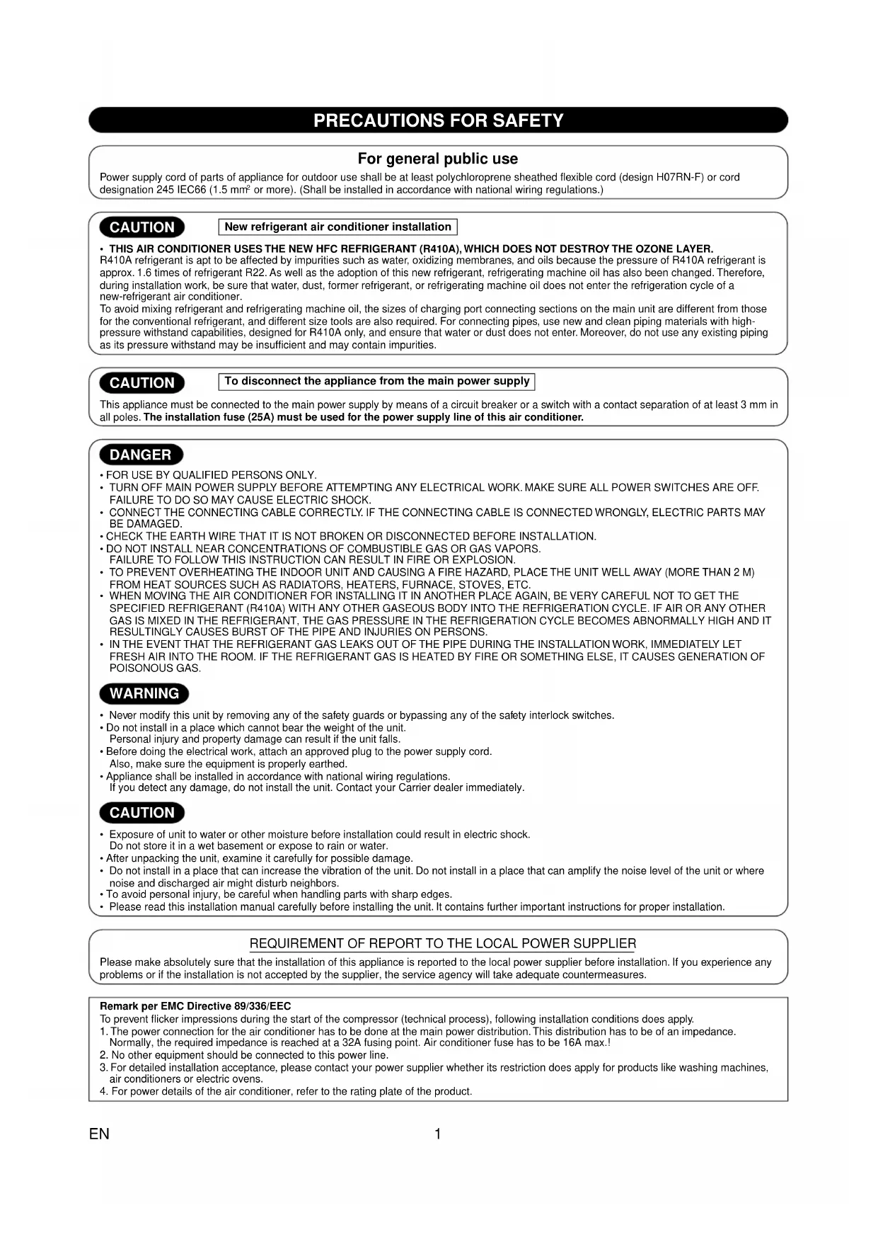
PRECAUTIONS FOR SAFETY
For general public use
Power supply cord of parts of appliance for outdoor use shall be at least polychloroprene sheathed flexible cord (design H07RN-F) or cord designation 245 IEC66 (1.5 mm² or more). (Shall be installed in accordance with national wiring regulations.)
CAUTION
New refrigerant air conditioner installation
- THIS AIR CONDITIONER USES THE NEW HFC REFRIGERANT (R410A), WHICH DOES NOT DESTROY THE OZONE LAYER.
R410A refrigerant is apt to be affected by impurities such as water, oxidizing membranes, and oils because the pressure of R410A refrigerant is approx. 1.6 times of refrigerant R22. As well as the adoption of this new refrigerant, refrigerating machine oil has also been changed. Therefore, during installation work, be sure that water, dust, former refrigerant, or refrigerating machine oil does not enter the refrigeration cycle of a new-refrigerant air conditioner.
To avoid mixing refrigerant and refrigerating machine oil, the sizes of charging port connecting sections on the main unit are different from those for the conventional refrigerant, and different size tools are also required. For connecting pipes, use new and clean piping materials with high-pressure withstand capabilities, designed for R410A only, and ensure that water or dust does not enter. Moreover, do not use any existing piping as its pressure withstand may be insufficient and may contain impurities.
CAUTION
To disconnect the appliance from the main power supply
This appliance must be connected to the main power supply by means of a circuit breaker or a switch with a contact separation of at least 3 mm in all poles. The installation fuse (25A) must be used for the power supply line of this air conditioner.
DANGER
• FOR USE BY QUALIFIED PERSONS ONLY.
- TURN OFF MAIN POWER SUPPLY BEFORE ATTEMPTING ANY ELECTRICAL WORK. MAKE SURE ALL POWER SWITCHES ARE OFF. FAILURE TO DO SO MAY CAUSE ELECTRIC SHOCK.
- CONNECT THE CONNECTING CABLE CORRECTLY. IF THE CONNECTING CABLE IS CONNECTED WRONGLY, ELECTRIC PARTS MAY BE DAMAGED.
- CHECK THE EARTH WIRE THAT IT IS NOT BROKEN OR DISCONNECTED BEFORE INSTALLATION.
- DO NOT INSTALL NEAR CONCENTRATIONS OF COMBUSTIBLE GAS OR GAS VAPORS. FAILURE TO FOLLOW THIS INSTRUCTION CAN RESULT IN FIRE OR EXPLOSION.
• TO PREVENT OVERHEATING THE INDOOR UNIT AND CAUSING A FIRE HAZARD, PLACE THE UNIT WELL AWAY (MORE THAN 2 M) FROM HEAT SOURCES SUCH AS RADIATORS, HEATERS, FURNACE, STOVES, ETC.
- WHEN MOVING THE AIR CONDITIONER FOR INSTALLING IT IN ANOTHER PLACE AGAIN, BE VERY CAREFUL NOT TO GET THE SPECIFIED REFRIGERANT (R410A) WITH ANY OTHER GASEOUS BODY INTO THE REFRIGERATION CYCLE. IF AIR OR ANY OTHER GAS IS MIXED IN THE REFRIGERANT, THE GAS PRESSURE IN THE REFRIGERATION CYCLE BECOMES ABNORMALLY HIGH AND IT RESULTINGLY CAUSES BURST OF THE PIPE AND INJURIES ON PERSONS.
- IN THE EVENT THAT THE REFRIGERANT GAS LEAKS OUT OF THE PIPE DURING THE INSTALLATION WORK, IMMEDIATELY LET FRESH AIR INTO THE ROOM. IF THE REFRIGERANT GAS IS HEATED BY FIRE OR SOMETHING ELSE, IT CAUSES GENERATION OF POISONOUS GAS.
WARNING
- Never modify this unit by removing any of the safety guards or bypassing any of the safety interlock switches.
- Do not install in a place which cannot bear the weight of the unit.
Personal injury and property damage can result if the unit falls. - Before doing the electrical work, attach an approved plug to the power supply cord.
Also, make sure the equipment is properly earthed. - Appliance shall be installed in accordance with national wiring regulations.
If you detect any damage, do not install the unit. Contact your Carrier dealer immediately.
CAUTION
- Exposure of unit to water or other moisture before installation could result in electric shock. Do not store it in a wet basement or expose to rain or water.
• After unpacking the unit, examine it carefully for possible damage. - Do not install in a place that can increase the vibration of the unit. Do not install in a place that can amplify the noise level of the unit or where noise and discharged air might disturb neighbors.
- To avoid personal injury, be careful when handling parts with sharp edges.
- Please read this installation manual carefully before installing the unit. It contains further important instructions for proper installation.
REQUIREMENT OF REPORT TO THE LOCAL POWER SUPPLIER
Please make absolutely sure that the installation of this appliance is reported to the local power supplier before installation. If you experience any problems or if the installation is not accepted by the supplier, the service agency will take adequate countermeasures.
Remark per EMC Directive 89/336/EEC
To prevent flicker impressions during the start of the compressor (technical process), following installation conditions does apply.
- The power connection for the air conditioner has to be done at the main power distribution. This distribution has to be of an impedance. Normally, the required impedance is reached at a 32A fusing point. Air conditioner fuse has to be 16A max.!
- No other equipment should be connected to this power line.
- For detailed installation acceptance, please contact your power supplier whether its restriction does apply for products like washing machines, air conditioners or electric ovens.
- For power details of the air conditioner, refer to the rating plate of the product.
INSTALLATION DIAGRAM OF INDOOR AND OUTDOOR UNITS
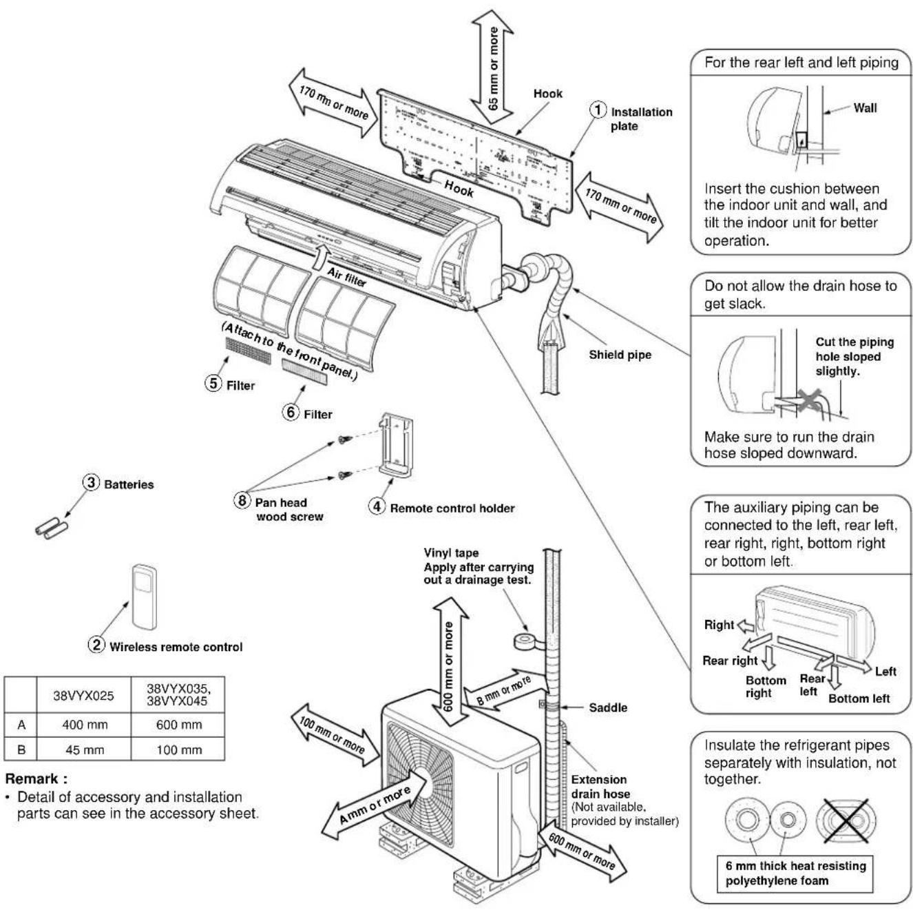
Optional Installation Parts
| Part code | Parts name | Q'ty |
| A | Refrigerant pipingLiquid side : ∅6.35 mmGas side : ∅9.52 mm (42HQV025, 42HQV035) : ∅12.70 mm (42HQV045) | One each |
| B | Pipe insulating material(polyethylene foam, 6 mm thick) | 1 |
| C | Putty, PVC tapes | One each |
Fixing bolt arrangement of outdoor unit
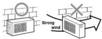
- Secure the outdoor unit with fixing bolts and nuts if the unit is likely to be exposed to a strong wind.
- Use ∅8 mm or ∅10 mm anchor bolts and nuts.
- If it is necessary to drain the defrost water, attach drain nipple ⑨ and cap water proof ⑩ to the bottom plate of the outdoor unit before installing it.
INDOOR UNIT
Installation Place
- A place which provides the spaces around the indoor unit as shown in the diagram
- A place where there are no obstacles near the air inlet and outlet
- A place which allows easy installation of the piping to the outdoor unit
- A place which allows the front panel to be opened
- The indoor unit shall be installed as top of the indoor unit comes to at least 2 m height. Also, it must be avoided to put anything on the top of the indoor unit.
CAUTION
- Direct sunlight to the indoor unit's wireless receiver should be avoided.
- The microprocessor in the indoor unit should not be too close to RF noise sources.
(For details, see the owner's manual.)
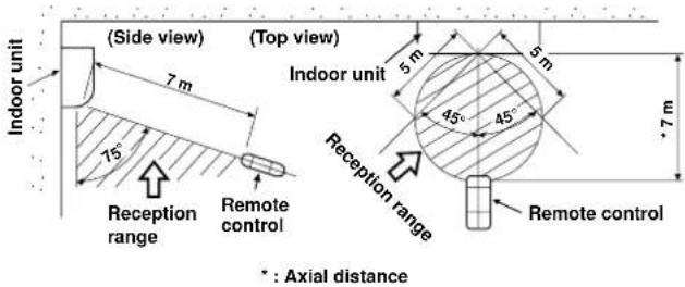
Remote control
- A place where there are no obstacles such as a curtain that may block the signal from the indoor unit
- Do not install the remote control in a place exposed to direct sunlight or close to a heating source such as a stove.
- Keep the remote control at least 1 m apart from the nearest TV set or stereo equipment. (This is necessary to prevent image disturbances or noise interference.)
- The location of the remote control should be determined as shown below.
Cutting a Hole and Mounting Installation Plate
Cutting a hole
When installing the refrigerant pipes from the rear
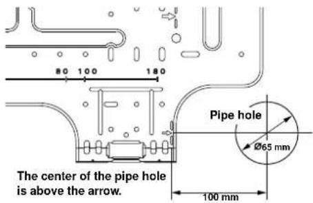
- After determining the pipe hole position on the mounting plate (→), drill the pipe hole (∅65 mm) at a slight downward slant to the outdoor side.
NOTE
- When drilling a wall that contains a metal lath, wire lath or metal plate, be sure to use a pipe hole brim ring sold separately.
Mounting the installation plate
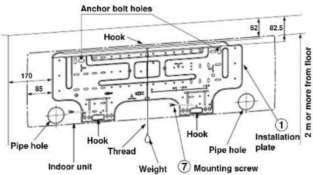
When the installation plate is directly mounted on the wall
- Securely fit the installation plate onto the wall by screwing it in the upper and lower parts to hook up the indoor unit.
- To mount the installation plate on a concrete wall with anchor bolts, use the anchor bolt holes as illustrated in the below figure.
- Install the installation plate horizontally in the wall.
CAUTION
When installing the installation plate with a mounting screw, do not use the anchor bolt holes. Otherwise, the unit may fall down and result in personal injury and property damage.
Installation plate
(Keep horizontal direction.)
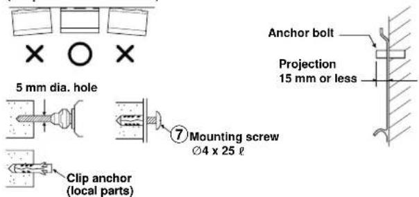
CAUTION
Failure to firmly install the unit may result in personal injury and property damage if the unit falls.
- In case of block, brick, concrete or similar type walls, make 5 mm dia. holes in the wall.
- Insert clip anchors for appropriate mounting screws ⑦.
NOTE
- Secure four corners and lower parts of the installation plate with 4 to 6 mounting screws to install it.
Electrical Work
- The supply voltage must be the same as the rated voltage of the air conditioner.
- Prepare the power source for exclusive use with the air conditioner.
NOTE
- Wire type: More than H07RN-F or 245 IEC66
CAUTION
- This appliance can be connected to the mains in either of the following two ways.
(1) Connection to fixed wiring:
A switch or circuit breaker which disconnects all poles and has a contact separation of at least 3 mm must be incorporated in the fixed wiring. An approved circuit breaker or switches must be used.
(2) Connection with power supply plug:
Attach power supply plug with power cord and plug it into wall outlet. An approved power supply cord and plug must be used.
NOTE
- Perform wiring works so as to allow a general wiring capacity.
Wiring Connection
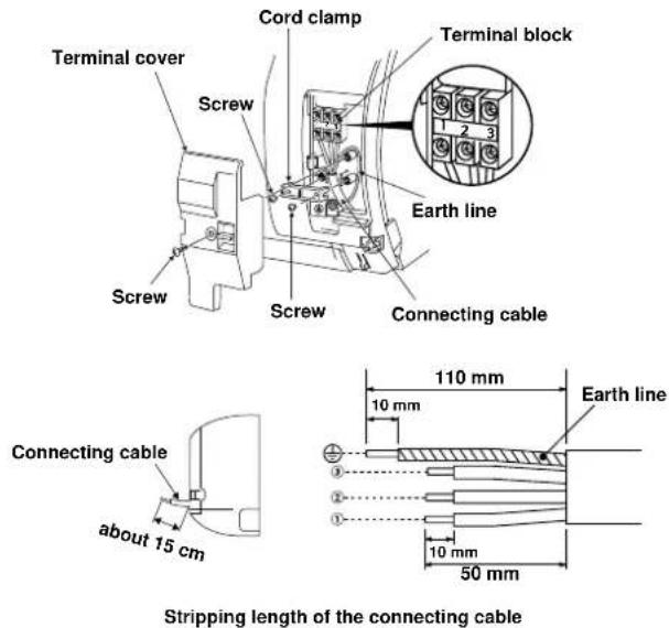
How to connect the connecting cable
Wiring of the connecting cable can be carried out without removing the front panel.
- Remove the air inlet grille.
Open the air inlet grille upward and pull it toward you. - Remove the terminal cover and cord clamp.
- Insert the connecting cable (according to the local cords) into the pipe hole on the wall.
- Take out the connecting cable through the cable slot on the rear panel so that it protrudes about 15 cm from the front.
- Insert the connecting cable fully into the terminal block and secure it tightly with screws.
6.Tightening torque : 1.2 N·m (0.12 kgf·m) - Secure the connecting cable with the cord clamp.
- Fix the terminal cover, rear plate bushing and air inlet grille on the indoor unit.
CAUTION
- Be sure to refer to the wiring system diagram labeled inside the front panel.
- Check local electrical cords and also any specific wiring instructions or limitations.
NOTE
- Use stranded wire only.
• Wire type : H07RN-F or more
How to install the air inlet grille on the indoor unit
- When attaching the air inlet grille, the contrary of the removed operation is performed.
natural_image
Diagram of a cylindrical air duct with internal flow arrows indicating direction (no text or symbols)Piping and Drain Hose Installation
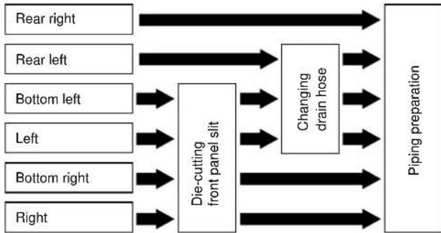
Piping and drain hose forming
* Since dewing results in a machine trouble, make sure to insulate both connecting pipes. (Use polyethylene foam as insulating material.)
flowchart
graph LR
    A["Left"] --> B["Die-cutting front panel slit"]
    C["Right"] --> B
    D["Bottom left"] --> B
    E["Bottom right"] --> B
    F["Left"] --> B
    G["Right"] --> B
    H["Top right"] --> B
    I["Top left"] --> B
    J["Top right"] --> B
    K["Top right"] --> B
    L["Top left"] --> M["Changing drain hose"]
    N["Top right"] --> M
    O["Top right"] --> M
    P["Top left"] --> M
    Q["Top right"] --> M
    R["Top right"] --> M
    S["Top left"] --> T["Piping preparation"]
    U["Top right"] --> T
    V["Top left"] --> T
    W["Top right"] --> T
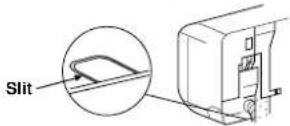
1. Die-cutting front panel slit
Cut out the slit on the leftward or right side of the front panel for the left or right connection and the slit on the bottom left or right side of the front panel for the bottom left or right connection with a pair of nippers.
2. Changing drain hose
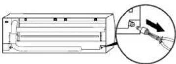
For leftward connection, bottom-leftward connection and rear-leftward connection's piping, it is necessary to change the drain hose and drain cap.
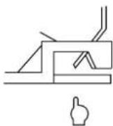
How to remove the drain cap
Clip the drain cap by needle-nose pliers and pull out.
natural_image
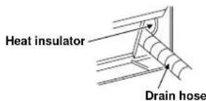
Technical diagram of a mechanical component with an inset showing a hand holding a tool (no text or symbols present)How to install the drain hose
Firmly insert drain hose connecting part until hitting on a heat insulator.
How to fix the drain cap
1) Insert hexagon wrench (4 mm) in a center head.
2) Firmly insert the drain cap.
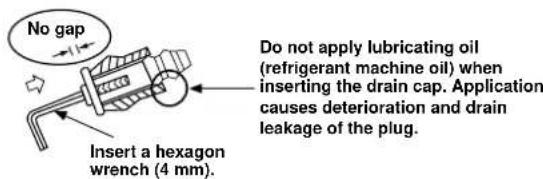
CAUTION
Firmly insert the drain hose and drain cap; otherwise, water may leak.
In case of right or left piping
• After scribing slits of the front panel with a knife or a making-off pin, cut them with a pair of nippers or an equivalent tool.

In case of bottom right or bottom left piping
• After scribing slits of the front panel with a knife or a making-off pin, cut them with a pair of nippers or an equivalent tool.
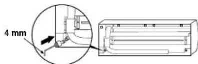
Left-hand connection with piping
Bend the connecting pipe so that it is laid within 43 mm above the wall surface. If the connecting pipe is laid exceeding 43 mm above the wall surface, the indoor unit may unstably be set on the wall. When bending the connecting pipe, make sure to use a spring bender so as not to crush the pipe.
Bend the connecting pipe within a radius of 30 mm.
To connect the pipe after installation of the unit (figure)
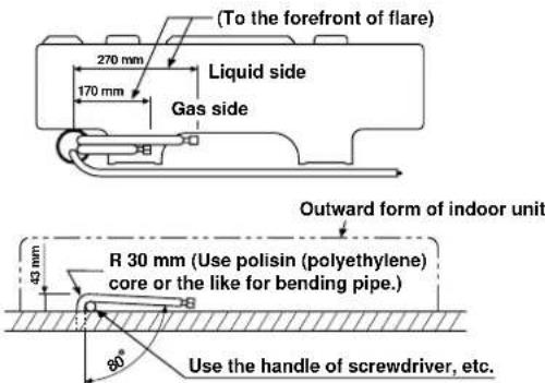
NOTE
If the pipe is bent incorrectly, the indoor unit may unstably be set on the wall.
After passing the connecting pipe through the pipe hole, connect the connecting pipes to the auxiliary pipes and wrap the facing tape around them.
CAUTION
- Bind the auxiliary pipes (two) and connecting cable with facing tape tightly. In case of leftward piping and rear-leftward piping, bind the auxiliary pipes (two) only with facing tape.

- Carefully arrange pipes so that any pipe does not stick out of the rear plate of the indoor unit.
- Carefully connect the auxiliary pipes and connecting pipes to one another and cut off the insulating tape wound on the connecting pipe to avoid double-taping at the joint; moreover, seal the joint with the vinyl tape, etc.
- Since dewing results in a machine trouble, make sure to insulate both connecting pipes. (Use polyethylene foam as insulating material.)
- When bending a pipe, carefully do it, not to crush it.
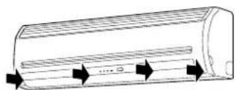
Indoor Unit Fixing
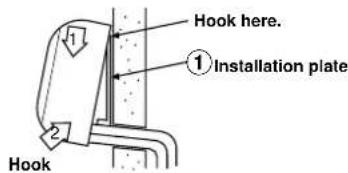
- Pass the pipe through the hole in the wall and hook the indoor unit on the installation plate at the upper hook.
- Swing the indoor unit to right and left to confirm that it is firmly hooked up on the installation plate.
- While pressing the indoor unit onto the wall, hook it at the lower part on the installation plate. Pull the indoor unit toward you to confirm that it is firmly hooked up on the installation plate.
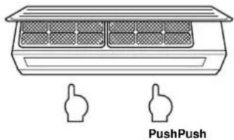
Press (unhook)
- For detaching the indoor unit from the installation plate, pull the indoor unit toward you while pushing its bottom up at the specified parts.
natural_image
Diagram of a multi-compartment air conditioner unit with two push push icons below (no text or symbols on the unit itself)Drainage
- Run the drain hose sloped downwards.
NOTE
- The hole should be made at a slight downward slant on the outdoor side.
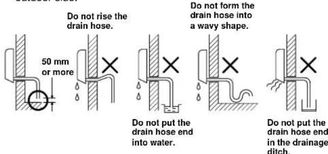
- Put water in the drain pan and make sure that the water is drained out of doors.
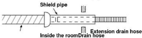
- When connecting extension drain hose, insulate the connecting part of extension drain hose with shield pipe.
CAUTION
Arrange the drain pipe for proper drainage from the unit. Improper drainage can result in dew-dropping.
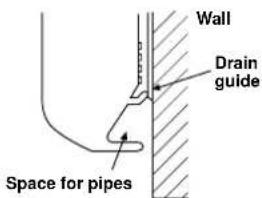
This air conditioner has the structure designed to drain water collected from dew, which forms on the back of the indoor unit, to the drain pan. Therefore, do not store the power cord and other parts at a height above the drain guide.
OUTDOOR UNIT
Installation Place
- A place which provides the spaces around the outdoor unit as shown in the diagram
- A place which can bear the weight of the outdoor unit and does not allow an increase in noise level and vibration
- A place where the operation noise and discharged air do not disturb your neighbors
• A place which is not exposed to a strong wind
• A place free of a leakage of combustible gases
• A place which does not block a passage - When the outdoor unit is to be installed in an elevated position, be sure to secure its feet.
- An allowable length of the connecting pipe is up to 10 m for 38VYX025 and 15 m for 38VYX035, 38VYX045.
- An allowable height level is up to 8 m for 38VYX025 and 10 m for 38VYX035, 38VYX045.
• A place where the drain water does not raise any problems
CAUTION
- Install the outdoor unit without anything blocking the air discharging.
- When the outdoor unit is installed in a place always exposed to strong wind like a coast or on a high storey of a building, secure the normal fan operation using a duct or a windshield.
- In particularly windy areas, install the unit such as to avoid admission of wind.
- Installation in the following places may result in trouble. Do not install the unit in such places.
• A place full of machine oil
• A saline-place such as the coast
• A place full of sulfide gas - A place where high-frequency waves are likely to be generated as from audio equipment, welders, and medical equipment
Refrigerant Piping Connection Evacuating
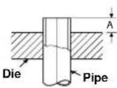
Flaring
- Cut the pipe with a pipe cutter.

- Insert a flare nut into the pipe and flare the pipe. • Projection margin in flaring : A (Unit : mm)
Rigid (clutch type)
| Outer dia. of copper pipe | R410A tool used Conventional tool used |
| 6.35 0 to 0.5 1.0 to 1.5 | |
| 9.52 0 to 0.5 1.0 to 1.5 | |
| 12.70 0 to 0.5 1.0 to 1.5 |
Imperial (wing nut type)
| Outer dia. of copper pipe | R410A |
| 6.35 | 1.5 to 2.0 |
| 9.52 | 1.5 to 2.0 |
| 12.70 | 2.0 to 2.5 |
Tightening connection
Align the centers of the connecting pipes and tighten the flare nut as far as possible with your fingers. Then tighten the nut with a spanner and torque wrench as shown in the figure.
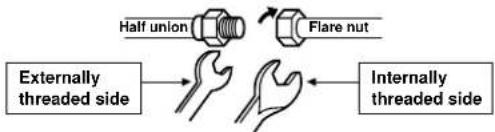
flowchart
graph LR
    A["Outerly threaded side"] --> B["Flare nut"]
    B --> C["Flare union"]
    C --> D["Internally threaded side"]
Use a wrench to secure.
Use a torque wrench to tighten.
CAUTION
Do not apply excess torque. Otherwise, the nut may crack depending on the conditions.
(Unit : N·m)
| Outer dia. of copper pipe | Tightening torque |
| ∅6.35 mm | 16 to 18 (1.6 to 1.8 kgf-m) |
| ∅9.52 mm | 30 to 42 (3.0 to 4.2 kgf-m) |
| ∅12.70 mm | 50 to 62 (5.0 to 6.2 kgf-m) |
- Tightening torque of flare pipe connections
The operating pressure of R410A is higher than that of R22 (approx. 1.6 times). It is therefore necessary to firmly tighten the flare pipe connecting sections (which connect the indoor and outdoor units) up to the specified tightening torque. Incorrect connections may cause not only a gas leakage, but also damage to the refrigeration cycle.
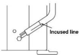
Shaping pipes
- How to shape the pipes Shape the pipes along the incused line on the outdoor unit.
- How to fit position of the pipes Put the edges of the pipes to the place with a distance of 85 mm from the incused line.
After the piping has been connected to the indoor unit, you can perform the air purge together at once.
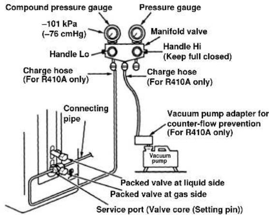
AIR PURGE
Evacuate the air in the connecting pipes and in the indoor unit using a vacuum pump. Do not use the refrigerant in the outdoor unit. For details, see the manual of the vacuum pump.
Using a vacuum pump
Be sure to use a vacuum pump with counter-flow prevention function so that inside oil of the pump does not flow backward into pipes of the air conditioner when the pump stops. (If oil inside of the vacuum pump enters the air conditioner, which use R410A, refrigeration cycle trouble may result.)
- Connect the charge hose from the manifold valve to the service port of the packed valve at gas side.
- Connect the charge hose to the port of the vacuum pump.
- Open fully the low pressure side handle of the gauge manifold valve.
- Operate the vacuum pump to start evacuating. Perform evacuating for about 15 minutes if the piping length is 20 meters. (15 minutes for 20 meters) (assuming a pump capacity of 27 liters per minute) Then confirm that the compound pressure gauge reading is -101 kPa (-76 cmHg).
- Close the low pressure side valve handle of the gauge manifold valve.
- Open fully the valve stem of the packed valves (both gas and liquid sides).
- Remove the charging hose from the service port.
- Securely tighten the caps on the packed valves.
CAUTION
- KEEP IMPORTANT 4 POINTS FOR PIPING WORK.
(1) Take away dust and moisture (inside of the connecting pipes).
(2) Tighten the connections (between pipes and unit).
(3) Evacuate the air in the connecting pipes using a VACUUM PUMP.
(4) Check gas leak (connected points).
Packed valve handling precautions
- Open the valve stem all the way out, but do not try to open it beyond the stopper.
- Securely tighten the valve stem cap with torque in the following table:
| Gas side 50 to 62 N·m(∅12.70 mm) (5.0 to 6.2 | |
| Gas side 30 to 42 N·m(∅9.52 mm) (3.0 to | |
| Liquid side 16 to 18 N·m(∅6.35 mm) (1.6 to | |
| Service port | 9 to 10 N·m(0.9 to 1.0 kgf·m) |
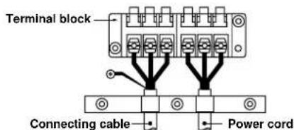
Wiring Connection
- Remove the valve cover from the outdoor unit.
- Connect the connecting cable to the terminals as identified with their respective matched numbers on the terminal block of indoor and outdoor unit.
- When connecting the connecting cable to the outdoor unit terminals, make a loop as shown in the installation diagram of indoor and outdoor unit to prevent water coming in the outdoor unit.
- Insulate the unused cords (conductors) from any water coming in the outdoor unit. Proceed them so that they do not touch any electrical or metal parts.
Stripping length of the connecting cable
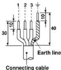
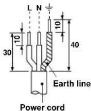
| Model | 42HQV025 | 42HQV035, 42HQV045 |
| Power source | 50/60Hz, 220 – 240 V Single phase | |
| Maximum running current | 8A | 11A |
| Plug socket & fuse rating | 25A | |
| Power cord | H07RN-F or 245 IEC66 (1.5 mm ^2 or more) | |
CAUTION
- Wrong wiring connection may cause some electrical parts burn out.
- Be sure to comply with local cords on running the wire from indoor unit to outdoor unit (size of wire and wiring method, etc.).
• Every wire must be connected firmly - This installation fuse (25A) must be used for the power supply line of this air conditioner.
- If incorrect or incomplete wiring is carried out, it will cause an ignition or smoke.
- Prepare the power supply for exclusive use with the air conditioner.
• This product can be connected to the mains.
Connection to fixed wiring: A switch which disconnects all poles and has a contact separation of at least 3 mm must be incorporated in the fixed wiring.
NOTE: Connecting cable
- Wire type : More than H07RN-F or 245 IEC66
OTHERS
Gas Leak Test
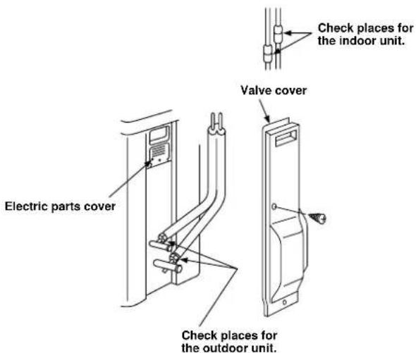
- Check the flare nut connections for the gas leak with a gas leak detector or soap water.
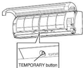
Test Operation
To switch the TEST RUN (COOL) mode, press TEMPORARY button for 10 seconds. (The beeper will make a short beep.)
Auto Restart Setting
This product is designed so that, after a power failure, it can restart automatically in the same operating mode as before the power failure.
Information
The product was shipped with Auto Restart function in the off position. Turn it on as required.
How to set the Auto Restart
- Press and hold the TEMPORARY button for about 3 seconds. After 3 seconds, the electronic beeper makes three short beeps to tell you the Auto Restart has been selected.
- To cancel the Auto Restart, follow the steps described in the section Auto Restart Function of the owner's manual.
natural_image
Diagram of a cylindrical object with internal parallel grooves and directional arrows indicating flow or movement (no text or symbols)natural_image
Diagram of a rectangular air conditioner unit with internal tubing and a magnified inset showing a hand holding a tool (no text or symbols present)natural_image
Diagram of a cylindrical air vent with internal flow arrows (no text or symbols)natural_image
Diagram of a rectangular air conditioner unit with internal tubing and a magnified inset showing airflow direction (no text or symbols)natural_image
Diagram of a container with two thumbs-up icons, no text or symbols presentDrainage
natural_image
Diagram of a cylindrical air duct with internal flow arrows indicating direction (no text or symbols)natural_image
Diagram of a rectangular appliance with grid compartments and two thumbs-down icons below (no text or symbols on the main diagram)Scarico
natural_image
Diagram of a cylindrical air vent with internal flow arrows indicating direction (no text or symbols)natural_image
Line drawing of a cylindrical air conditioner unit with ventilation slots and airflow arrows (no text or symbols)natural_image
Technical diagram of a rectangular device with internal channels and a magnified inset showing a mechanical component (no text or symbols)natural_image
Line drawing of a rectangular container with two side handles, no text or symbols presentDrenagem
flowchart
graph TD
    A["Lado com rosca interna"] --> B["Hand with hands"]
    C["Mela união"] --> D["Hand with hands"]
    E["Porca cónica"] --> F["Hand with hands"]
    G["Lado com rosca externa"] --> H["Hand with hands"]
    I["Hand with hands"] --> J["Hand with hands"]
natural_image
Line drawing of a cylindrical air conditioner unit with airflow arrows indicating direction (no text or symbols)natural_image
Diagram of a rectangular air conditioner unit with internal cooling pipes and a magnified inset showing internal components (no text or labels)natural_image
Diagram of a cylindrical air duct with internal flow arrows indicating direction (no text or symbols)natural_image
Diagram of a rectangular device with internal channels and a magnified inset showing a mechanical component (no text or symbols)natural_image
Diagram of a cylindrical air duct with internal flow arrows indicating direction (no text or symbols)natural_image
Diagram of a rectangular device with internal channels and a magnified inset showing a mechanical component (no text or symbols)natural_image
Diagram of a container with three grilles and two thumbs-up icons, labeled 'DrukkenDrukken' (no text or symbols on the diagram itself)Afvoer
natural_image
Diagram of a cylindrical object with internal parallel grooves and directional arrows indicating flow or movement (no text or symbols)natural_image
Diagram of a rectangular device with internal channels and an inset showing a mechanical component (no text or symbols)Montera dräneringsslangen
natural_image
Diagram of a cylindrical object with internal parallel grooves and directional arrows indicating flow or movement (no text or symbols)natural_image
Diagram of a rectangular air conditioner unit with internal tubing and a magnified inset showing a hand holding a tool (no text or symbols present)natural_image
Line drawing of a rectangular appliance with two side handles, no text or symbols presentTyönnäTyönnä
Vedenpoisto
natural_image
Diagram of a cylindrical object with internal parallel grooves and directional arrows indicating flow or movement (no text or symbols)1. Stanset spor i frontpanel
natural_image
Technical diagram of a rectangular air duct system with internal channels and a magnified inset showing a tool interacting with a pipe (no text or labels)Innstillinger for Auto Restart
- AIR CONDITIONER (SPLIT TYPE)
- INDOOR UNIT
- OUTDOOR UNIT
- OTHERS
- CONTENIDOS
- INNEHÅLLSLFÖRTECKNING
- INOMHUSENHETEN
- INNENHETEN
- PRECAUTIONS FOR SAFETY
- For general public use
- CAUTION
- New refrigerant air conditioner installation
- To disconnect the appliance from the main power supply
- DANGER
- WARNING
- REQUIREMENT OF REPORT TO THE LOCAL POWER SUPPLIER
- Remark per EMC Directive 89/336/EEC
- Fixing bolt arrangement of outdoor unit
- Installation Place
- Remote control
- Cutting a Hole and Mounting Installation Plate
- Cutting a hole
- NOTE
- When the installation plate is directly mounted on the wall
- Electrical Work
- Wiring Connection
- How to connect the connecting cable
- How to install the air inlet grille on the indoor unit
- Piping and Drain Hose Installation
- Piping and drain hose forming
- Die-cutting front panel slit
- Changing drain hose
- How to remove the drain cap
- How to install the drain hose
- How to fix the drain cap
- In case of right or left piping
- In case of bottom right or bottom left piping
- Left-hand connection with piping
- Bend the connecting pipe within a radius of 30 mm.
- Indoor Unit Fixing
- Drainage
- Refrigerant Piping Connection Evacuating
- Flaring
- Tightening connection
- - Tightening torque of flare pipe connections
- Shaping pipes
- AIR PURGE
- Using a vacuum pump
- - KEEP IMPORTANT 4 POINTS FOR PIPING WORK.
- Packed valve handling precautions
- Stripping length of the connecting cable
- NOTE: Connecting cable
- Gas Leak Test
- Test Operation
- Auto Restart Setting
- Information
- How to set the Auto Restart
- Scarico
- Drenagem
- Afvoer
- Montera dräneringsslangen
- Vedenpoisto
- Stanset spor i frontpanel
- Innstillinger for Auto Restart
Brand : CARRIER
Model : 42HQV035
Category : Air Conditioning