
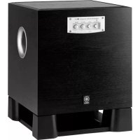
Soavo900SW - Subwoofer YAMAHA - Free user manual and instructions
Find the device manual for free Soavo900SW YAMAHA in PDF.
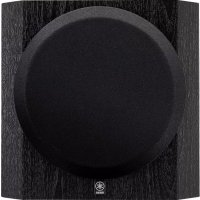
| Type | Subwoofer with Advanced YST II technology |
| Speaker | 25 cm cone with magnetic shielding |
| Output power | 600 W (100 Hz, 4 Ω, 10% THD) |
| Frequency response | 18 Hz – 160 Hz |
| Power consumption | 180 W (standby: 0.5 W) |
| Power supply | AC 110/120/220/230-240 V, 50/60 Hz depending on version |
| Inputs | Line (RCA): INPUT 3 ; LFE: INPUT 2 ; Speakers: INPUT 1 (binding posts) |
| Outputs | Front speakers: OUTPUT (binding posts) |
| Ground terminal | GND for noise reduction |
| Remote control | Infrared, AA batteries included |
| Functions | Volume, H-CUT, Phase, B.A.S.S. (Wide/Normal/Narrow), timer (120 min), PRESET memory (3) |
| Supplied accessories | Power cable, remote control, batteries |
| Maintenance | Soft dry cloth; avoid solvents |
| Safety | Do not open, avoid humidity, 20 cm free space around, do not block ventilation |
| Repairability | Contact a YAMAHA authorized service center |
Frequently Asked Questions - Soavo900SW YAMAHA
User questions about Soavo900SW YAMAHA
0 question about this device. Answer the ones you know or ask your own.
Ask a new question about this device
Download the instructions for your Subwoofer in PDF format for free! Find your manual Soavo900SW - YAMAHA and take your electronic device back in hand. On this page are published all the documents necessary for the use of your device. Soavo900SW by YAMAHA.
USER MANUAL Soavo900SW YAMAHA
CAUTION: Read this before operating your unit.
Please read the following operating precautions before use.
YAMAHA will not be held responsible for any damage and/or injury caused by not following the cautions below.
1 To assure the finest performance, please read this manual carefully. Keep it in a safe place for future reference.
2 Install this unit in a cool, dry, clean place - away from windows, heat sources, sources of excessive vibration, dust, moisture and cold. Avoid sources of humming (transformers, motors).
3 Never open the cabinet. If something drops into the set, contact your dealer.
4 The voltage to be used must be the same as that specified on the rear panel. Using this unit with a higher voltage than specified is dangerous and may cause a fire and/or electric shock.
5 To reduce the risk or fire or electric shock, do not expose this unit to rain or moisture.
6 Do not use force on switches, controls or connection wires. When moving the unit, first disconnect the power plug and the wires connected to other equipments. Never pull the wires themselves.
7 When not planning to use this unit for a long period (ie., vacation, etc.), disconnect the AC power plug from the wall outlet.
8 Since this unit has a built-in power amplifier, heat will radiate from the rear panel. Place the unit apart from the walls, allowing at least 20cm of space above, behind and on both sides of the unit to prevent fire or damage. Furthermore, do not position with the rear panel facing down on the floor or other surfaces.
9 Do not cover the rear panel of this unit with a newspaper, a tablecloth, a curtain, etc. in order not to obstruct heat radiation. If the temperature inside the unit rises, it may cause fire, damage to the unit and/or personal injury.
10 Do not place the following objects on this unit:
- Glass, china, small metallic etc.
If glass etc. falls by vibrations and breaks, it may cause bodily injury. - A burning candle etc.
If the candle falls by vibrations, it may cause fire and bodily injury.
-A vessel with water in it
If the vessel falls by vibrations and water spills, it may cause damage to the speaker, and/or you may get an electric shock.
11 Do not place this unit where foreign objects such as water drips might fall. It might cause a fire, damage to this unit, and/or personal injury.
12 Never put a hand or a foreign object into the YST port located on the front side of this unit. When moving this unit, do not hold the port as it might cause personal injury and/or damage to this unit.
13 Never place a fragile object near the YST port of this unit. If the object falls or drops by the air pressure, it may cause damage to the unit and/or personal injury.
14 Never open the cabinet. It might cause an electric shock since this unit uses a high voltage. It might also cause personal injury and/or damage to this unit.
15 When using a humidifier, be sure to avoid condensation inside this unit by allowing enough spaces around this unit or avoiding excess humidification. Condensation might cause a fire, damage to this unit, and/or electric shock.
16 Super-bass frequencies reproduced by this unit may cause a turntable to generate a howling sound. In such a case, move this unit away from the turntable.
17 This unit may be damaged if certain sounds are continuously output at high volume level. For example, if 20Hz - 50Hz sine waves from a test disc, bass sounds from electronic instruments, etc. are continuously output, or when the stylus of a turntable touches the surface of a disc, reduce the volume level to prevent this unit from being damaged.
18 If you hear distorted noise (i.e., unnatural, intermittent "rapping" or "hammering" sounds) coming from this unit, reduce the volume level. Extremely loud playing of a movie soundtrack's low frequency, bass-heavy sounds or similarly loud popular music passages can damage this speaker system.
19 Vibration generated by super-bass frequencies may distort images on a TV. In such a case, move this unit away from the TV set.
20 Do not attempt to clean this unit with chemical solvents as this might damage the finish. Use a clean, dry cloth.
21 Be sure to read the "TROUBLESHOOTING" section regarding common operating errors before concluding that the unit is faulty.
22 Install this unit near the wall outlet and where the AC power plug can be reached easily.
23 The batteries shall not be exposed to excessive heat such as sunshine, fire or the like.
24 Secure placement or installation is the owner's responsibility. YAMAHA shall not be liable for any accident caused by improper placement or installation of speakers.
This unit features a magnetically shielded design, but there is still a chance that placing it too close to a TV set might impair picture color. Should this happen, move this unit away from the TV set.
This unit is not disconnected from the AC power source as long as it is connected to the wall outlet, even if this unit itself is turned off. In this state, this unit is designed to consume a very small quantity of power.
VOLTAGE SELECTOR
(Asia and General models only)
The voltage selector switch on the rear panel of this unit must be set for your local main voltage BEFORE plugging this unit into the AC main supply. Voltages are 110/120/220/230-240 V AC, 50/60 Hz.
For U.K. customers
If the socket outlets in the home are not suitable for the plug supplied with this appliance, it should be cut off and an appropriate 3 pin plug fitted. For details, refer to the instructions described below.
Note: The plug severed from the mains lead must be destroyed, as a plug with bared flexible cord is hazardous if engaged in a live socket outlet.
SPECIAL INSTRUCTIONS FOR U.K. MODEL
IMPORTANT:
THE WIRES IN MAINS LEAD ARE COLOURED IN ACCORDANCE WITH THE FOLLOWING CODE:
Blue: NEUTRAL
Brown: LIVE
As the colours of the wires in the mains lead of this apparatus may not correspond with the coloured markings identifying the terminals in your plug, proceed as follows: The wire which is coloured BLUE must be connected to the terminal which is marked with the letter N or coloured BLACK. The wire which is coloured BROWN must be connected to the terminal which is marked with the letter L or coloured RED. Making sure that neither core is connected to the earth terminal of the three pin plug.
CONTENTS
GETTING STARTED 2
Features 2
About this manual 2
Supplied accessories 2
Controls and functions. 3
Preparing the remote control. 5
PLACEMENT 6
CONNECTIONS 7
1 Connecting to the amplifier equipped with subwoofer (line out) terminal(s) 7
2 Connecting to an amplifier not equipped with a subwoofer (line out) terminal. 9
Connecting to the ground terminal 12
Connecting the power cable 12
USING THIS UNIT 13
Adjusting the sound balance. 13
Storing the sound balance settings 14
Setting the sleep timer 14
Operating the power of this unit using the remote control of your amplifier 15
Frequency response. 16
Advanced Yamaha
Active Servo Technology II 17
TROUBLESHOOTING 18
SPECIFICATIONS 19
GETTING STARTED
Features
High 600 W dynamic power
L.F.E input terminal
Sleep timer
Remote control capability
You can make setting changes and adjustments for this unit by using the remote control from your listening position.
Advanced Yamaha Active Servo Technology II
This unit employs Advanced Yamaha Active Servo Technology II which Yamaha has developed for reproducing higher quality super-bass sound.
Two input connections
This unit can be easily added to your existing audio system by connecting to either the speaker terminals or the line output (pin jack) terminals of the amplifier.
Optimum bass sounds with various settings
Setting high cut and phase keeps the optimum sound quality balance between the front speakers and this unit.
B.A.S.S. mode button
This unit is equipped with the B.A.S.S. mode button so that you can enjoy bass sound that matches any kind of source.
About this manual
- In this manual, operations that can be performed using either the front panel of this unit or the remote control are explained using the remote control.
- indicates a tip for your operation.
- Notes contain important information about safety and operating instructions.
Supplied accessories
Check that you have received all of the following parts.

Power cable

Batteries (2) (AA, R6, UM-3)
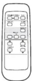
Remote control
Controls and functions
■Front panel
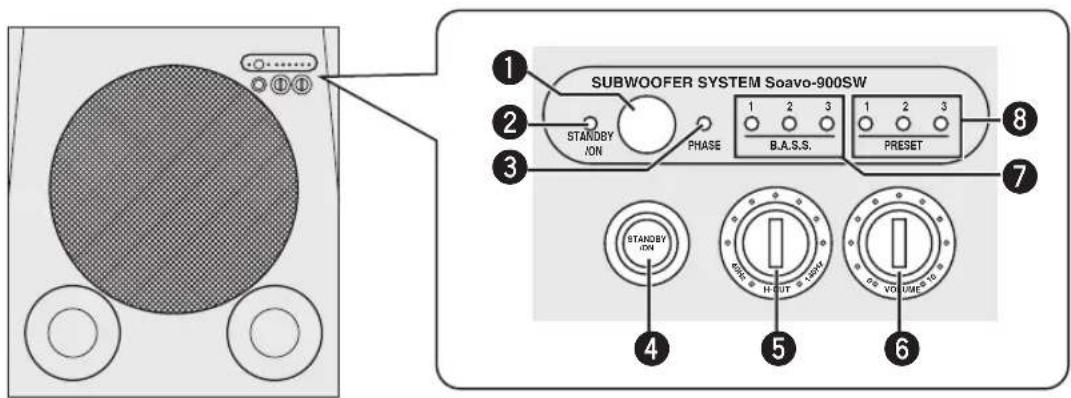
Remote control sensor
Receives signals from the remote control.
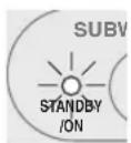
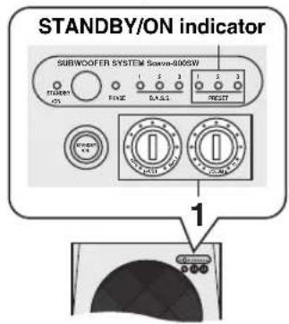
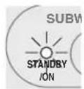
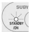
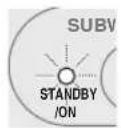
STANDBY/ON indicator
Green: Lights up when this unit is on.
Red: Lights up when this unit is in the standby mode.
Orange: Lights up when the sleep timer is on.
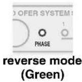
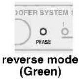
3PHASE indicator
Green: Lights up when the phase is set in the reverse mode.
Red: Lights up when the phase is set in the regular mode.
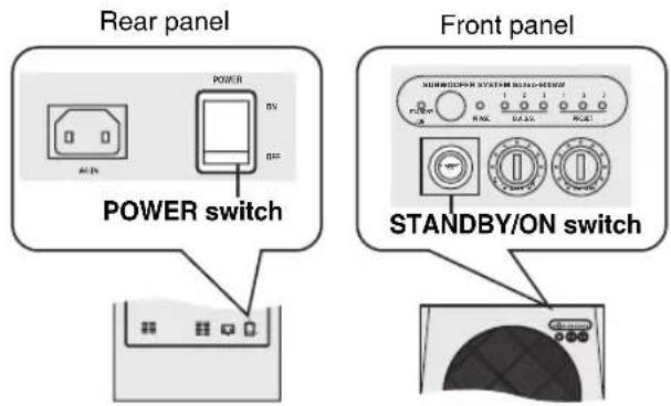
4STANDBY/ON switch
Turns on or sets this unit to the standby mode.
Note
In the standby mode, this unit consumes a small amount of power.
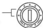
H-CUT control
Adjusts the high frequency cut off point depending on the connected front speakers or your preference (see page 13).
One graduation of this control represents 10Hz
Rear panel
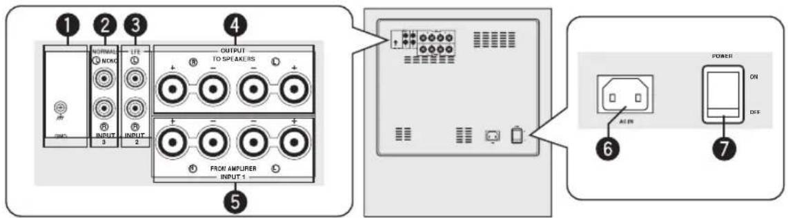
GND terminal
See page 12 for connection information.
2INPUT 3 terminals
See pages 7 - 8 for connection information.
INPUT 2 (LFE) terminals
See page 8 for connection information.
4OUTPUT terminals
See page 10 for connection information.
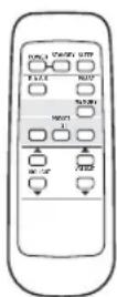
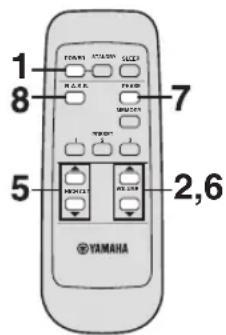
Remote control
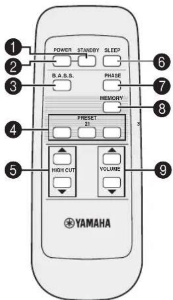
STANDBY
Sets this unit to the standby mode.
Note
In the standby mode, this unit consumes a small amount of power.
POWER
Turns on this unit.
INPUT 1 terminals
See pages 10 - 11 for connection information.
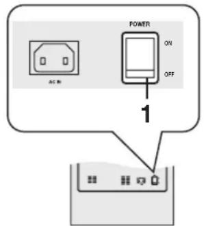
6AC IN
Connects the supplied power cable (see page 12).
7 POWER switch
Switches the power (ON/OFF) of this unit. Normally, set this switch to the ON position. When this unit is not used for a long period of time, set the switch to the OFF position.
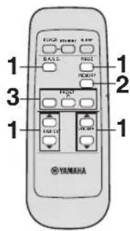
B.A.S.S.
Selects a mode that is suitable for the source. Each time you press B.A.S.S., the B.A.S.S. indicator changes between 1, 2, and 3.
4 PRESET
Stores or recalls the B.A.S.S., volume, high-cut frequency and phase settings (see page 14).
5 HIGH CUT
Adjusts the high frequency cut off point depending on the connected front speakers or your preference (see page 13).
6 SLEEP
Sets the sleep timer (see page 14).
7PHASE
Switches the phase mode.
Normally, set this unit to the reverse position. However, according to your speaker systems or the listening condition, there may be cases when better sound quality is obtained by setting this switch to the normal position. Select the better position by monitoring the sound.
8 MEMORY
Stores the B.A.S.S., volume, high-cut frequency and phase settings (see page 14).
9VOLUME
Adjusts the volume of this unit.
Preparing the remote control
■Installing the batteries in the remote control
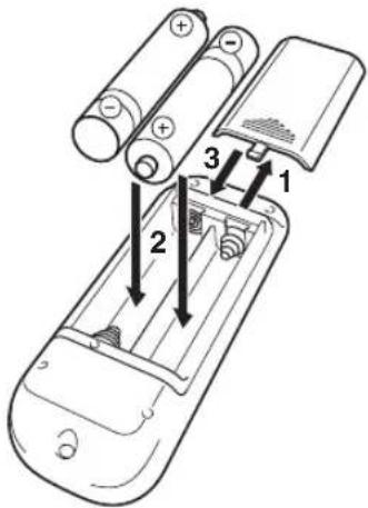
1 Press the mark on the battery cover and open the cover.
2 Insert the two supplied type AA, R6, UM-3 batteries following the indications (+/-) inside the battery compartment.
3 Close the battery cover.
Replacing the batteries
Change all of the batteries if you notice conditions such as the operation range of the remote control decreases.
Notes
- Do not use an old battery together with a new one.
- Do not use different types of batteries (for example, alkaline and manganese) together. Each type of battery has its own characteristics even if they are similar in shape.
- If the batteries run out, immediately remove them from the remote control to prevent an explosion or acid leak.
- Dispose of the batteries according to the regional regulations.
- If a battery starts leaking, dispose of it immediately. Be careful not to let leaking battery acid come into contact with your skin or clothing. Before inserting new batteries, wipe the compartment clean.
Using the remote control
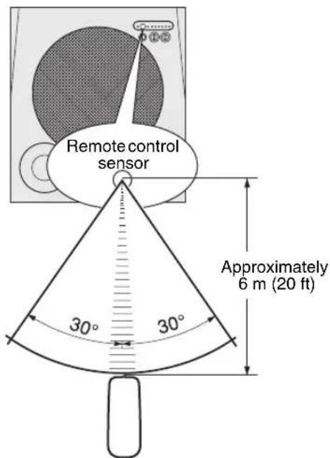
The remote control transmits a directional infrared ray. Be sure to aim the remote control directly at the remote control sensor on the main unit during operation.
Handling the remote control
Be careful not to spill liquid on the remote control.
Be careful not to drop the remote control.
Do not leave the remote control in the following places:
hot or humid places, such as near a heater or in a bathroom
extremely cold places
-dustyplaces
PLACEMENT
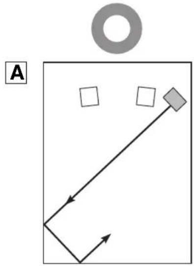
The position of the subwoofer is not so critical because bass sound is not highly directional. For a sonorous sound field, the use of two subwoofoers is recommended, although you can obtain a good effect with one subwoofer. ( : subwoofer, : front speaker)
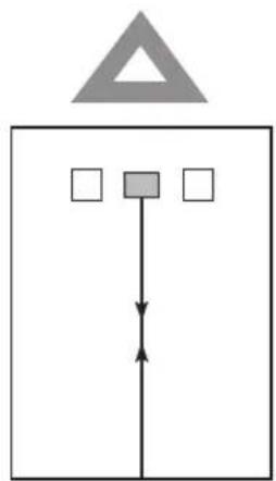
■When using one subwoofer
Place the subwoofer on the outside of either the right or the left front speaker.
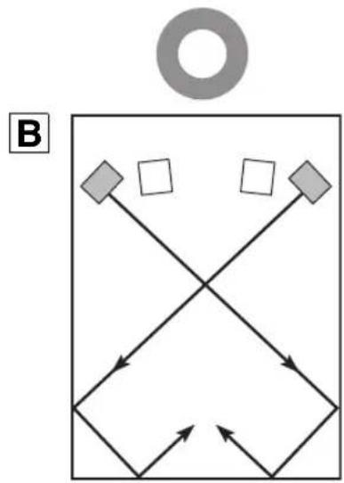
When using two subwoofoers
Place the subwoofoers on the outside of each front speaker.
#
If the subwoofer is placed directly facing the wall, the bass sound may lessen because the sound from the subwoofer and the sound reflected by the wall may cancel each other out. To prevent this from happening, face the subwoofer obliquely to the wall (A)
CONNECTIONS
See pages 7 - 8 when your amplifier has subwoofer (line out) terminal(s), or see pages 9 - 11 when your amplifier has no subwoofer (line out) terminal.
Notes
- Do not connect the power cord of this unit and other components into an AC outlet until all connections between components are completed.
- Be sure to connect the left channel (L), right channel (R), "+" (red) and "-" (black) properly. Also, refer to the owner's manual of your component to be connected to this unit.
- The connection methods or the names of the terminals may differ depending on the component. Refer to the owner's manual of your component as well.
Connecting to the amplifier equipped with subwoofer (line out) terminal(s)
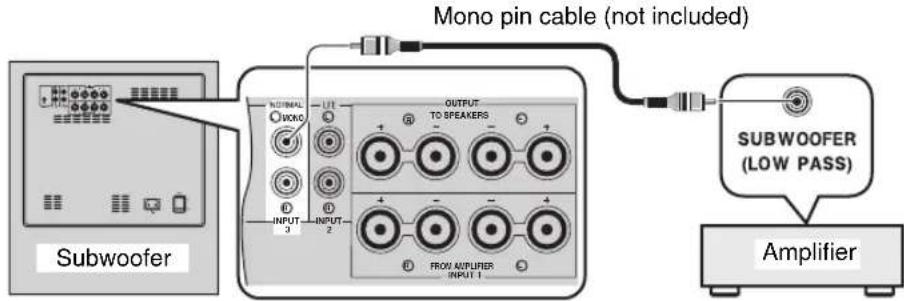
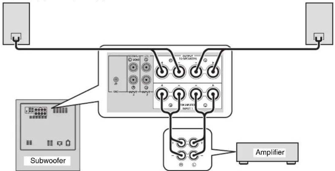
When your amplifier has a one-channel subwoofer terminal
Connect the subwoofer (or low pass etc.) terminal of your amplifier to the INPUT 3 (①/MONO) terminal of this unit using a commercially available mono pin cable.
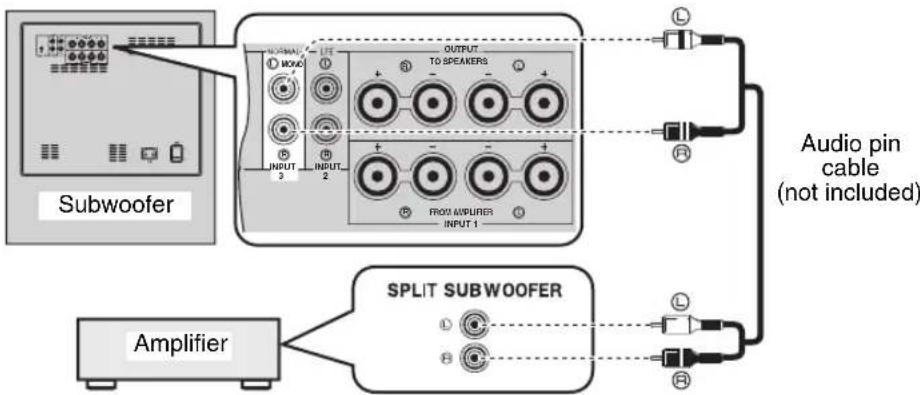
When your amplifier has two-channel subwoofer terminals
Using one subwoofer
Connect the "L" side subwoofer terminal of your amplifier to the INPUT 3 ( /MONO) terminal of this unit and "R" side subwoofer terminal of your amplifier to the INPUT 3 (R) terminal of this unit using a commercially available audio pin cable.
Notes
- Some amplifiers have line output terminals labeled PRE OUT. When you connect this unit to the PRE OUT terminals of the amplifier, make sure that the amplifier has at least two sets of PRE OUT terminals. If the amplifier has only one set of PRE OUT terminals, do not connect this unit to the PRE OUT terminals. Instead, connect this unit to the speaker terminals of the amplifier (see pages 9 - 10).
- When connecting to a monaural line output terminal of the amplifier, connect the INPUT 3 (①/MONO) terminal.
- When connecting to line output terminals of the amplifier, other speakers should not be connected to the OUTPUT terminals on the rear panel of this unit. If connected, they will not produce sound.
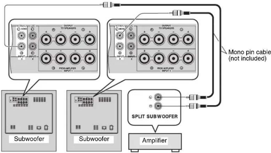
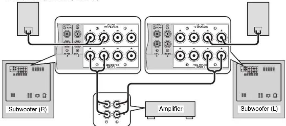
Using two subwoofoers
Connect the "R" side subwoofer terminal of your amplifier to the INPUT 3 (R) terminal on this unit using a commercially available mono pin cable, and connect the "L" side subwoofer terminal of your amplifier to the INPUT 3 (L/MONO) terminal of this unit using a commercially available mono pin cable.
Connecting to an amplifier equipped with a high cut function
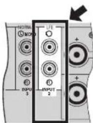
If your amplifier can cut off high frequencies from the signals for sending to the subwoofer, connect the amplifier to the INPUT 2 (LFE) terminal of this unit. This brings you higher sound quality because the signal routing in this unit is shortened by bypassing the built-in HIGH CUT (high cut) circuit.
2 Connecting to an amplifier not equipped with a subwoofer (line out) terminal
Connect an amplifier (and front speakers) to this unit using commercially available speaker cables. Refer to the following instructions to make connections.
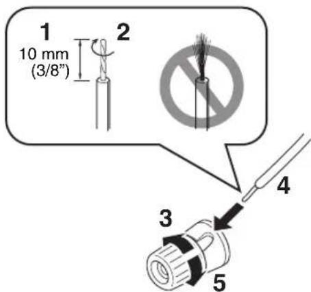
Connecting to the speaker cable
Banana plug connection
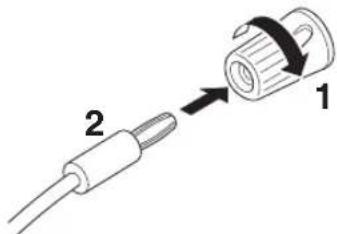
1 Tighten the knob.
2 Insert the banana plug connector into the end of the corresponding terminal.
1 Remove approximately 10mm (3 / 8^ ) of insulation from each of the speaker cables.
2 Twist the exposed wires of the cable together to prevent short circuits.
3 Turn the knob counterclockwise to loosen.
4 Insert the bare wire into the hole in the side of each terminal.
5 Turn the knob clockwise to tighten.
6 Test the firmness of the connection by pulling gently on the cable at the terminal.
Notes
- Do not let the bare speaker wires touch each other, because this could damage this unit or the amplifier, or both of them.
- For connection, keep the speaker cables as short as possible. Do not bundle or roll up the excess part of the cables. If the connections are faulty, no sound will be heard from this unit or the speakers, or both of them.
- Make sure that the + and - polarity markings of the speaker terminals are observed and set correctly. If these cables are reversed, the sound will be unnatural and lack bass.
- Do not insert the insulation into the hole. The sound may not be produced.
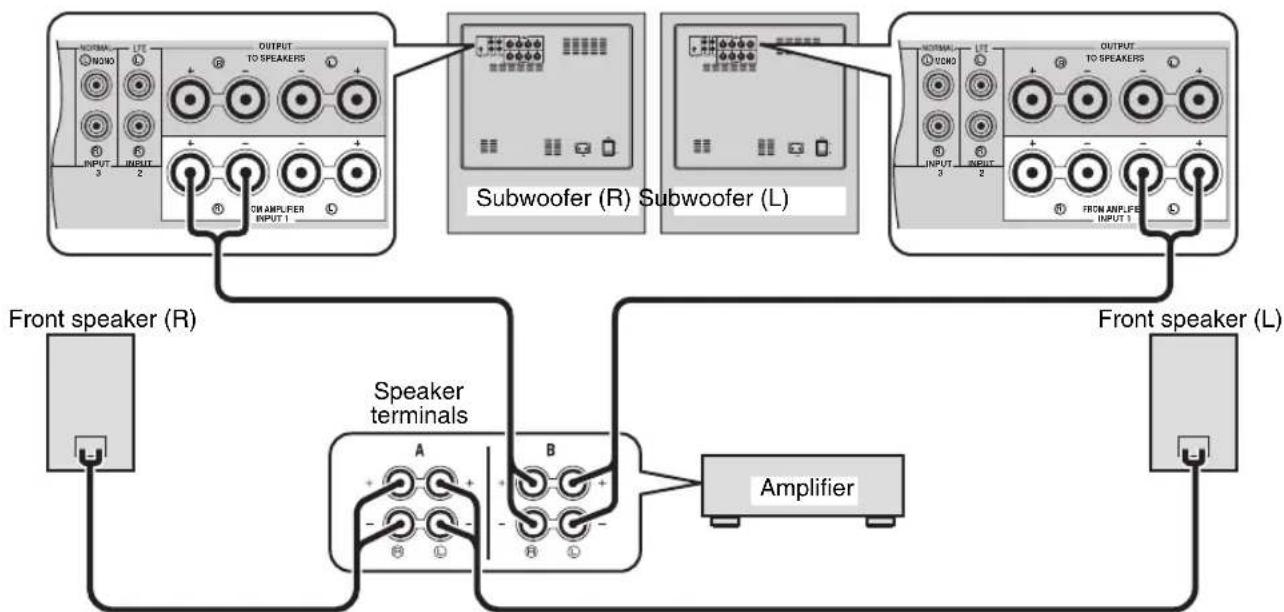
When your amplifier has one set of front speaker terminals
Connect the speaker terminals of the amplifier to the INPUT 1 terminals of this unit, and connect the OUTPUT terminals of this unit to the front speakers using a commercially available speaker cable.
中
Connecting front speakers via this unit does not affect the sound quality.
Using one subwoofer
Front speaker (R) Front speaker (L)
Speaker terminals
Using two subwoofoers
Front speaker (R) Front speaker (L)
Speaker terminals
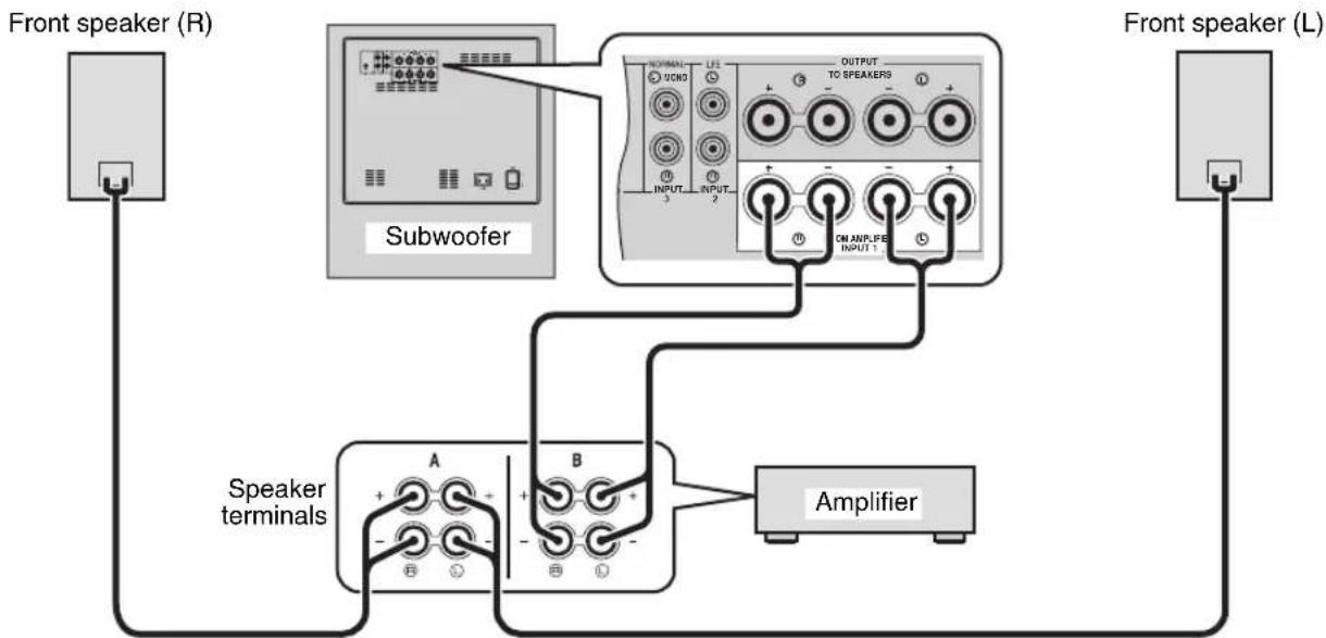
When your amplifier has two sets of front speaker terminals and both terminals can output sound signals simultaneously
- Connect one set of front speaker terminals of the amplifier to the INPUT 1 terminals of this unit, and connect another set of front speaker terminals of the amplifier to the front speakers using commercially available speaker cables.
- Set the amplifier so that both sets of front speaker terminals output sound signals simultaneously.
Note
When your amplifier cannot output sound signals simultaneously even if you connect in this way, follow "When your amplifier has one set of front speaker terminals" on page 10.
Using one subwoofer
Using two subwoofoers
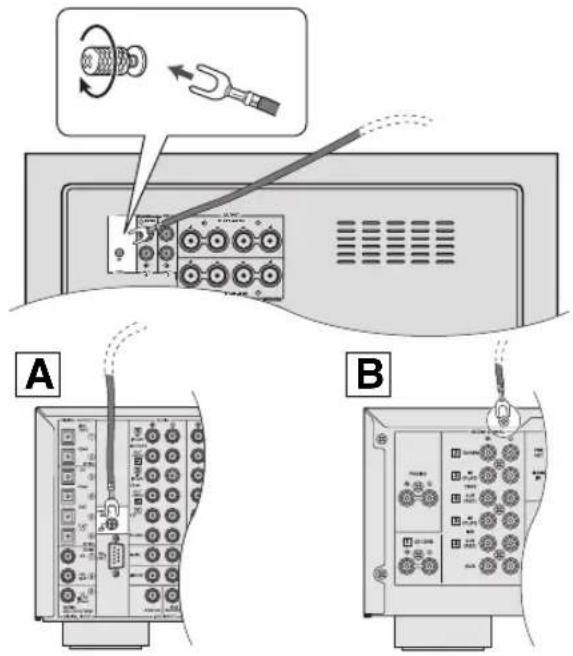
Connecting to the ground terminal
If this unit or the amplifier makes a hamming noise when connecting to the speaker terminals of your amplifier, connect both of the GND (ground) terminals on your amplifier and this unit using commercially available grounding wire as shown in fig. A
When your amplifier has no GND (ground) terminal, connect to the screw that fastens the top cover of your amplifier as shown in fig. 8
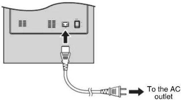
Connecting the power cable
Plug the supplied power cable into the AC IN of this unit after all other connections are complete, and then plug the power cable to an AC outlet.
Notes
- Do not use other power cables. Use the provided cable. Use of other power cables may result in fire hazard or electrical shock.
- Do not plug the power cable into the AC outlet of your amplifier. Doing so may create distorted sounds or turn off the power of your amplifier.
Note
When connecting the GND (ground) terminal, make sure the power cables of the amplifier and this unit are not plugged into the AC outlet.
Adjusting the sound balance
Before using this unit, adjust the volume balance of this unit to obtain the optimum volume and tone balance between the front speakers and this unit by following the procedures below.
Remote control
Rear panel
1 Set POWER switch on the rear panel of this unit to the ON position, and then press POWER to turn on this unit.
The STANDBY/ON indicator lights up green.
2 Press VOLUME to set the volume level of this unit to the minimum (0).
3 Turn on the power of all other components.
4 Play back a source containing low-frequency components and adjust the volume level of your amplifier to the desired listening level.
Set the tone control on your amplifier to the center position.
5 Press HIGH CUT / to adjust to the position where the desired response can be obtained.
Normally, set the position to a level slightly higher than the minimum frequency of the front speaker.
- To find out the minimum frequency of the front speaker, refer to the owner's manual of the front speaker.
6 Press VOLUME to increase the volume gradually to adjust the volume balance between the front speaker and this unit.
Normally, set the volume to a level where you can obtain a little more bass effect than when this unit is not used.

If you cannot obtain the desired response, repeat steps 5 and 6.
7 Press PHASE to select the regular or reverse mode.
Normally, set it to the reverse mode. If you cannot obtain the desired response, set it to the regular mode.
8 Press B.A.S.S. to select a mode that is suitable for the source.
1:WIDE
When a movie source is played, the low-frequency effects are enhanced so that you can enjoy more powerful sound.
2: NORMAL
When a music or movie etc. source is played, you can enjoy natural bass sounds.
3: NARROW
When an ordinary music source is played, the excessive low-frequency signals are cut off to make the sound clearer.
Storing the sound balance settings
You can store up to 3 sets of your favorite settings (volume, high-cut, phase and B.A.S.S. setting) in this unit.
Remote control
Front panel
Storing the setting
In the following procedure, PRESET 1 is used as an example.
1 Adjust the sound balance between the volume, high cut, phase and B.A.S.S. (see page 13).
2 Press MEMORY.
The PRESET indicators on the front panel flash.
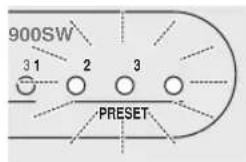
3 Press PRESET 1.
The PRESET 1 indicator lights up. The current setting is stored as PRESET 1.
- In step 3, pressing a stored number overwrites the old setting.
- While the VOLUME control or the H-CUT control is rotating by pressing a PRESET, pressing another PRESET is ineffective.
Recalling a setting
Press PRESET you want to recall (1, 2 or 3).
Memory back-up
Even if you turn off this unit by using the POWER switch on the rear panel, this unit recalls the last setting when the power is turned back on (Last memory function).
Note
If the power is cut for more than one week, the setting is cleared.
Setting the sleep timer
If you set the sleep timer, this unit automatically turns to the standby mode after 120 minutes.
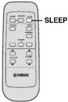
Press SLEEP.
The color of the STANDBY/ON indicator changes to orange.
Pressing SLEEP again cancels the sleep timer.
Operating the power of this unit using the remote control of your amplifier
-
This function is available only for Yamaha amplifiers that meet the following conditions:
-
The amplifier was released in 2005 or later.
- The remote control of the amplifier has two different buttons for STANDBY and ON.
Note
When the AMP ID library code of the remote control has been changed, this function may not work.
Setting
1 Set POWER switch on the rear panel to the OFF position.
2 Set POWER switch to the ON position while pressing and holding STANDBY/ON switch on the front panel.
Continue holding down STANDBY/ON switch for 3 seconds or longer.

After the STANDBY/ON indicator flashes 4 times, the setting is completed.
■Canceling
1 Set POWER switch on the rear panel to the OFF position.
2 Set POWER switch to the ON position while pressing and holding STANDBY/ON switch on the front panel.
Continue holding down STANDBY/ON switch for 3 seconds or longer.

After the STANDBY/ON indicator flashes 2 times, the setting is completed.
Note
Place this unit within the operating range of the remote control of the amplifier. If you place this unit far away from the amplifier, you may not be able to operate this unit with the remote control.
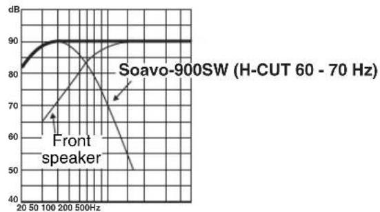
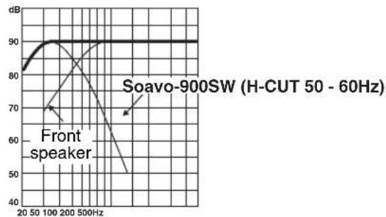
Frequency response
Frequency response of this unit
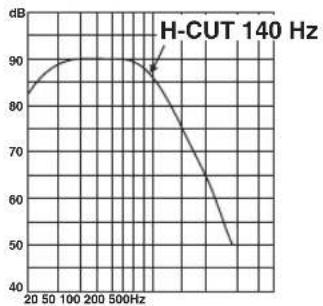
Frequency response graph*
The figures below show the optimum adjustment of each control and the frequency response when this subwoofer is combined with a typical front speaker system.
■EX.1 When combined with a 10 cm or 13 cm (3-15/16" or 5-2/16") acoustic suspension, 2 way system front speakers
If you are using Soavo-1 speakers as front speakers, use the following example as a reference when adjusting settings.

(H-CUT) (VOLUME)

(PHASE)
Frequency response graph*
■EX.2 When combined with a 20 cm or 25 cm (7-14/16" or 9-13/16") acoustic suspension, 2 way system front speakers

(H-CUT) (VOLUME)

(PHASE)
Frequency response graph*
- These diagrams do not depict actual frequency response characteristics accurately.
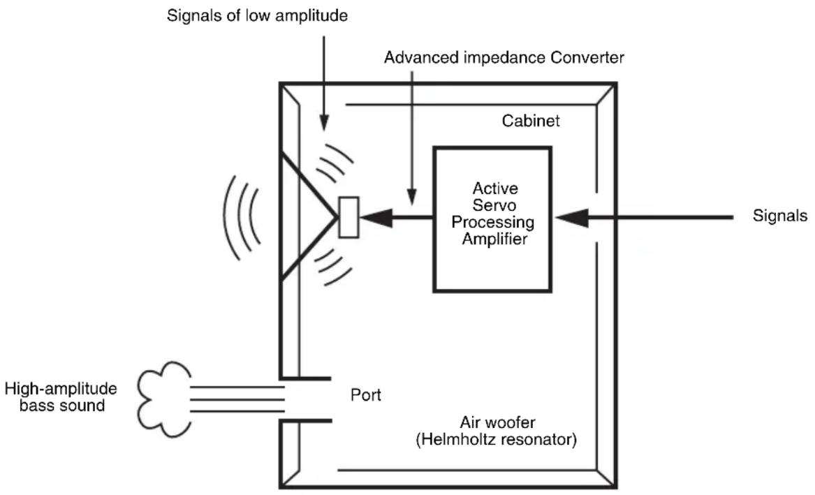
Advanced Yamaha Active Servo Technology II
In 1988, Yamaha brought to the speaker systems utilizing YST (Yamaha Active Servo Technology) to give powerful, high quality bass reproduction. This technology uses a direct connection between the amplifier and speaker, allowing accurate signal transmission and precise speaker control.
As this technology uses speaker units controlled by the negative impedance drive of the amplifier and resonance generated between the cabinet capacity volume and port, it creates more resonant energy (the "air woofer" concept) than the standard bass reflex method. This allows for bass reproduction from much smaller cabinets than was previously possible.
Yamaha's newly developed Advanced YST II adds many refinements to Yamaha Active Servo Technology, allowing better control of the forces driving the amplifier and speaker. From the amplifier's point of view, the speaker impedance changes depending on the sound frequency. Yamaha developed a new circuit design combining negative-impedance and constant-current drives, which provides a more stable performance and clear bass reproduction without any murkiness.
TROUBLESHOOTING
Refer to the chart below when this unit does not function properly. If the problem you are experiencing is not listed below or if the instructions given below do not help, disconnect the power cord and contact your authorized Yamaha dealer or service center.
| Problem Cause Remedy | ||
| Power is not supplied even though the STANDBY/ON switch is pressed. | The power plug is not securely connected. | Connect it securely. |
| The POWER switch is set to the OFF position. | Set the POWER switch to the ON position. | |
| No sound. The volume is set to the minimum (0). Raise the volume. | ||
| Speaker cables are not connected securely. | Connect them securely. | |
| The signals from the amplifier are too low. Increase | Increase the volume of the amplifier or the component connected to the amplifier. | |
| The signal from the subwoofer output terminal of the amplifier is not output. | Check the speaker mode setting on the amplifier. | |
| Sound level is too low. | Speaker cables are not connected correctly. | Connect them correctly, that is L (left) to L, R (right) to R, “+” to “+” and “-” to “-”. |
| Setting of the phase is not proper. Set the phase | to the other position. | |
| A source sound with few bass frequencies is being played. | Play a source sound with bass frequencies. Set the H-CUT to a higher position. | |
| It is influenced by standing waves. Reposition | this unit or break up the parallel surface by placing bookshelves etc. along the walls. | |
| The remote control does not work. | Wrong distance or angle. Use the remote control | within a maximum range of 6 m and no more then 30 degrees off-axis from the front panel. |
| Direct sunlight or lighting from an inverter type of fluorescent lamp etc. is striking the remote control sensor of this unit. | Reposition this unit. | |
| The batteries are weak. | Replace all batteries. | |
| This unit is not turned on with the remote control of the amplifier. (when setting “Operating the power of this unit using the remote control of your amplifier”) | Wrong distance or angle. | Place this unit within the operating range of the remote control of the amplifier. |
| The household breaker goes off. | This unit consumes much electricity when a high level signal is input to this unit. | Turn down the volume on the amplifier etc. connected to this unit or cut off the power of other unused equipment. |
Notes
- When an excessive level of signal is input to this unit for 5 to 15 minutes, the POWER indicator starts flashing to alarm you of the danger of damaging the power amplifier and speaker of this unit. If the signal input lasts for 5 minutes more, this unit turns into the standby mode automatically.
- When an enormous amount of signal is input, the power of this unit is turned off immediately. To turn on this unit again, press STANDBY/ON switch on the front panel.
SPECIFICATIONS
Type .... Advanced Yamaha Active Servo Technology II
Driver 25 cm (10") cone woofer Magnetic shielding type
Amplifier Output (100 Hz, 4 ohms, 10% T.H.D)
600W
Frequency Response 18 Hz - 160 Hz
Power Supply
U.S.A. and Canada models AC 120 V,60 Hz
U.K. and Europe models AC 230 V, 50 Hz
Australia model AC 240 V,50 Hz
Asia and General models
AC 110/120/220/230-240 V, 50/60 Hz
Korea model AC 220 V, 60 Hz
China model AC 220 V, 50 Hz
Power Consumption 180 W
Standby Power Consumption 0.5 W
Dimensions (WxHxD)
410 mm x 457 mm x 462 mm
(16-1/8" x 17" x 18-3/16")
Weight 32 kg (70 lbs. 9 oz.)
Please note that all specifications are subject to change without notice.
Advanced Yamaha Active Servo Technology II
Piles (2)
(AA, R6, UM-3)
Advanced Yamaha Active Servo Technology II
Dimensions (L x H x P)
410mm× 457mm× 462mm
Poids 32 kg
Advanced Yamaha Active Servo Technology II
Advanced Yamaha Active Servo Technology II
Advanced Yamaha Active Servo Technology II
Advanced Yamaha Active Servo Technology II
Advanced Yamaha Active
Servo Technology II 17
DIAGNOSTICA 18
DATI TECNICI 19
PER COMINIARE
Caratteristiche
Advanced Yamaha Active Servo Technology II
Advanced Yamaha Active Servo Technology II
Dimensioni (L x A x P)
410mm× 457mm× 462mm
Peso 32 kg
Advanced Yamaha Active Servo Technology II
Pilas (2)
(AA, R6, UM-3)
Mando a distancia
Advanced Yamaha Active Servo Technology II
Advanced Yamaha Active Servo Technology II
Advanced Yamaha Active Servo Technology II

- CAUTION: Read this before operating your unit.
- VOLTAGE SELECTOR
- For U.K. customers
- SPECIAL INSTRUCTIONS FOR U.K. MODEL
- IMPORTANT:
- CONTENTS
- GETTING STARTED
- Features
- About this manual
- Supplied accessories
- Controls and functions
- ■Front panel
- Remote control sensor
- STANDBY/ON indicator
- 3PHASE indicator
- 4STANDBY/ON switch
- Note
- H-CUT control
- Rear panel
- GND terminal
- 2INPUT 3 terminals
- INPUT 2 (LFE) terminals
- 4OUTPUT terminals
- Remote control
- STANDBY
- POWER
- INPUT 1 terminals
- 6AC IN
- POWER switch
- B.A.S.S.
- PRESET
- HIGH CUT
- SLEEP
- 7PHASE
- MEMORY
- 9VOLUME
- Preparing the remote control
- ■Installing the batteries in the remote control
- Replacing the batteries
- Notes
- Using the remote control
- Handling the remote control
- PLACEMENT
- ■When using one subwoofer
- When using two subwoofoers
- #
- CONNECTIONS
- Connecting to the amplifier equipped with subwoofer (line out) terminal(s)
- When your amplifier has a one-channel subwoofer terminal
- When your amplifier has two-channel subwoofer terminals
- Using one subwoofer
- Using two subwoofoers
- Connecting to an amplifier equipped with a high cut function
- Connecting to an amplifier not equipped with a subwoofer (line out) terminal
- Connecting to the speaker cable
- Banana plug connection
- When your amplifier has one set of front speaker terminals
- When your amplifier has two sets of front speaker terminals and both terminals can output sound signals simultaneously
- Connecting to the ground terminal
- Connecting the power cable
- Adjusting the sound balance
- 1:WIDE
- 2: NORMAL
- 3: NARROW
- Storing the sound balance settings
- Storing the setting
- Recalling a setting
- Memory back-up
- Setting the sleep timer
- Press SLEEP.
- Operating the power of this unit using the remote control of your amplifier
- Setting
- ■Canceling
- Frequency response
- Frequency response of this unit
- ■EX.1 When combined with a 10 cm or 13 cm (3-15/16" or 5-2/16") acoustic suspension, 2 way system front speakers
- ■EX.2 When combined with a 20 cm or 25 cm (7-14/16" or 9-13/16") acoustic suspension, 2 way system front speakers
- Advanced Yamaha Active Servo Technology II
- TROUBLESHOOTING
- SPECIFICATIONS
- Advanced Yamaha Active
- Servo Technology II 17
- DIAGNOSTICA 18
- DATI TECNICI 19
- PER COMINIARE
- Caratteristiche
Brand : YAMAHA
Model : Soavo900SW
Category : Subwoofer