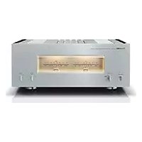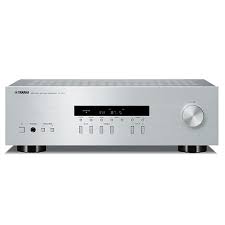
R-S201 - Home cinema amp YAMAHA - Free user manual and instructions
Find the device manual for free R-S201 YAMAHA in PDF.


User questions about R-S201 YAMAHA
0 question about this device. Answer the ones you know or ask your own.
Ask a new question about this device
Download the instructions for your Home cinema amp in PDF format for free! Find your manual R-S201 - YAMAHA and take your electronic device back in hand. On this page are published all the documents necessary for the use of your device. R-S201 by YAMAHA.
USER MANUAL R-S201 YAMAHA
Important Notice: Guarantee Information for customers in EEA\* and Switzerland
English
For detailed guarantee information about this Yamaha product, and Pan-EEA* and Switzerland warranty service, please either visit the website address below (Printable file is available at our website) or contact the Yamaha representative office for your country. * EEA: European Economic Area
1 To assure the finest performance, please read this manual carefully. Keep it in a safe place for future reference.
2 Install this sound system in a well ventilated, cool, dry, clean place - away from direct sunlight, heat sources, vibration, dust, moisture, and/or cold. For proper ventilation, allow the following minimum clearances around this unit.
Top: 30 cm (11-3/4 in)
Rear: 20 cm (7-7/8 in)
Sides: 20 cm (7-7/8 in)
3 Locate this unit away from other electrical appliances, motors, or transformers to avoid humming sounds.
4 Do not expose this unit to sudden temperature changes from cold to hot, and do not locate this unit in an environment with high humidity (i.e. a room with a humidifier) to prevent condensation inside this unit, which may cause an electrical shock, fire, damage to this unit, and/or personal injury.
5 Avoid installing this unit where foreign object may fall onto this unit and/or this unit may be exposed to liquid dripping or splashing. On the top of this unit, do not place:
- Other components, as they may cause damage and/or discoloration on the surface of this unit.
- Burning objects (i.e. candles), as they may cause fire, damage to this unit, and/or personal injury.
- Containers with liquid in them, as they may fall and liquid may cause electrical shock to the user and/or damage to this unit.
6 Do not cover this unit with a newspaper, tablecloth, curtain, etc. in order not to obstruct heat radiation. If the temperature inside this unit rises, it may cause fire, damage to this unit, and/or personal injury.
7 Do not plug in this unit to an AC wall outlet until all connections are complete.
8 Do not operate this unit upside-down. It may overheat, possibly causing damage.
9 Do not use force on switches, knobs and/or cords.
10 When disconnecting the power cable from the AC wall outlet, grasp the plug; do not pull the cable.
11 Do not clean this unit with chemical solvents; this might damage the finish. Use a clean, dry cloth.
12 Only voltage specified on this unit must be used. Using this unit with a higher voltage than specified is dangerous and may cause fire, damage to this unit, and/or personal injury. Yamaha will not be held responsible for any damage resulting from use of this unit with a voltage other than specified.
13 To prevent damage by lightning, keep the power cable and outdoor antennas disconnected from an AC wall outlet or this unit during a lightning storm.
14 Do not attempt to modify or fix this unit. Contact qualified Yamaha service personnel when any service is needed. The cabinet should never be opened for any reasons.
15 When not planning to use this unit for long periods of time (i.e. vacation), disconnect the AC power plug from the AC wall outlet.
16 Be sure to read the “TROUBLESHOOTING” section on common operating errors before concluding that this unit is faulty.
17 Before moving this unit, press Ⓧ (power) to set this unit to standby mode, and then disconnect the AC power plug from the AC wall outlet.
18 Condensation will form when the surrounding temperature changes suddenly. Disconnect the power cable from the outlet, then leave this unit alone.
19 When using this unit for a long time, this unit may become warm. Turn the power off, then leave this unit alone for cooling.
20 Install this unit near the AC wall outlet and where the AC power plug can be reached easily.
21 The batteries shall not be exposed to excessive heat such as sunshine, fire or the like.
22 Excessive sound pressure from earphones and headphones can cause hearing loss.
This unit is not disconnected from the AC power source as long as it is connected to the AC wall outlet, even if this unit itself is turned off by . This state is called the standby mode. In this state, this unit is designed to consume a very small quantity of power.
WARNING
TO REDUCE THE RISK OF FIRE OR ELECTRIC SHOCK, DO NOT EXPOSE THIS UNIT TO RAIN OR MOISTURE.

This label is required to be attached to a product of which the temperature of the top cover may be hot during operation.
■ For U.K. customers
If the socket outlets in the home are not suitable for the plug supplied with this appliance, it should be cut off and an appropriate 3 pin plug fitted. For details, refer to the instructions described below.
Note
The plug severed from the mains lead must be destroyed, as a plug with bared flexible cord is hazardous if engaged in a live socket outlet.
■ Special Instructions for U.K. Model
IMPORTANT
THE WIRES IN MAINS LEAD ARE COLOURED IN ACCORDANCE WITH THE FOLLOWING CODE:
Blue: NEUTRAL
Brown: LIVE
As the colours of the wires in the mains lead of this apparatus may not correspond with the coloured markings identifying the terminals in your plug, proceed as follows:
The wire which is coloured BLUE must be connected to the terminal which is marked with the letter N or coloured BLACK.
The wire which is coloured BROWN must be connected to the terminal which is marked with the letter L or coloured RED.
Make sure that neither core is connected to the earth terminal of the three pin plug.
CONTENTS
INTRODUCTION
USEFUL FEATURES....1
SUPPLIED ACCESSORIES .... 1
CONTROLS AND FUNCTIONS ...... 2
Front panel 2
Front panel display 4
Rear panel 5
Remote control....6
Using the remote control 8
PREPARATION
CONNECTIONS 9
Connecting speakers and source components...... 9
Connecting the FM and AM antennas.... 11
Connecting power cable 11
BASIC OPERATION
PLAYBACK....12
Playing a source.... 12
Using the sleep timer 13
FM/AM TUNING....14
Using preset functions 14
Receiving Radio Data System information (Only for Europe model)....18
ADVANCED OPERATION
SETTING THE OPTION MENU FOR EACH
INPUT SOURCE....19
Option menu items.... 19
ADDITIONAL INFORMATION
TROUBLESHOOTING ....20
SPECIFICATIONS....23
About this manual
- indicates a tip for your operation.
- The instructions in this manual describe the operation of this unit with the supplied remote control. You can also use the buttons or knobs on the front panel if they have the same or similar names as those on the remote control.
USEFUL FEATURES
This unit allows you to:
◆ Listen to FM and AM radio stations (see page 14)
◆ Use the remote control of this unit to operate a Yamaha CD player (see page 7)
◆ Save power by using the AUTO POWER STANDBY function (see page 19)
SUPPLIED ACCESSORIES
Please check that you received all of the following parts.
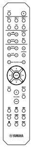
Remote control
Indoor FM antennas
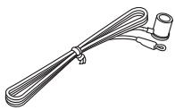
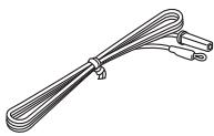
* One of the above is supplied depending on the region of purchase.
AM loop antenna
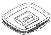
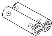
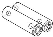
Batteries (x2)
(AA, R6, UM-3)
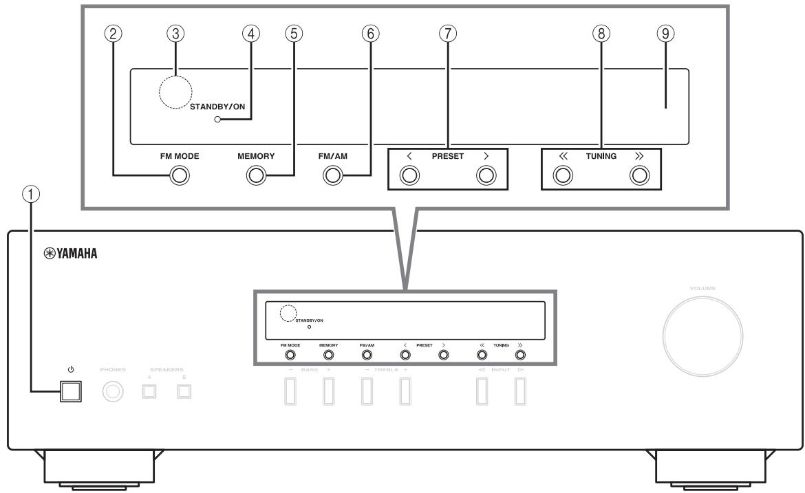
Front panel
text_image
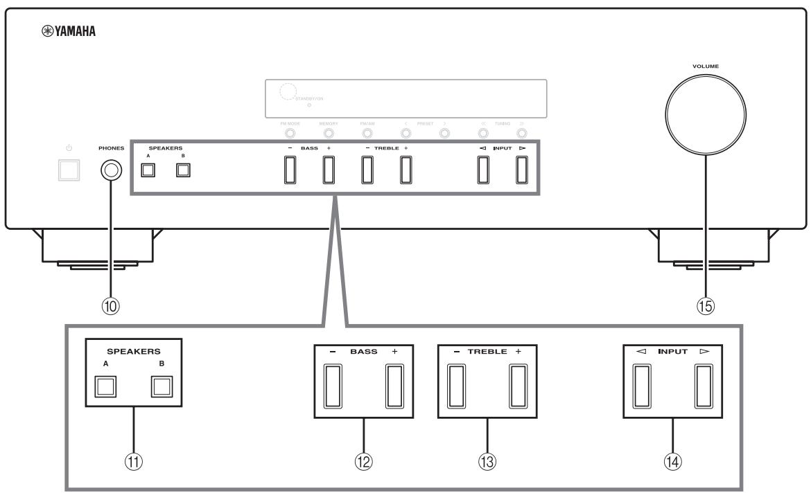
STANDBY/ON FM MODE MEMORY FM/AM < PRESET > << TUNING ># YAMAHA STANDBY/ON FM MODE MEMORY FM/AM < PRESET > << TUNING ># VOLUME PHONES SPEAKERS A B BASS TREBLE TNIPUT① ⏻ (power)
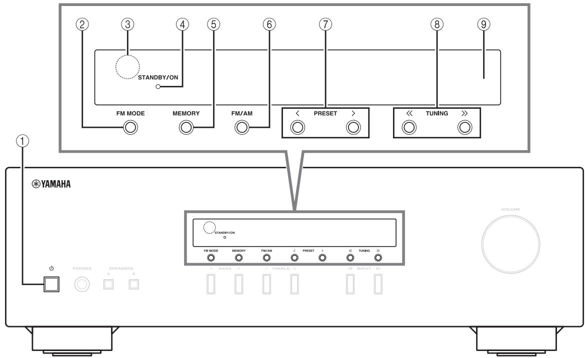
Turns this unit on, or sets it to standby mode.
Note
This unit consumes a small amount of power even when in standby mode.
② FM MODE
Changes the FM radio wave reception mode (stereo or monaural) when TUNER is selected as the input source (see page 14).
③ Remote control sensor
Receives infrared signals from the remote control.
④ STANDBY/ON indicator
| Indicator | Status |
| Brightly lit | The power of this unit is “on”. |
| Dimly lit | This unit is in “standby” mode. |
| Off | The power of this unit is “off”. To turn off this unit, disconnect the power cable from an AC wall outlet. |
⑤ MEMORY
Stores the current FM/AM station as a preset when TUNER is selected as the input source (see page 15).
⑥ FM/AM
Sets the FM/AM tuner band to FM or AM when TUNER is selected as the input source (see page 14).
⑦ PRESET < / >
Selects a preset FM/AM station when TUNER is selected as the input source (see page 16).
⑧ TUNING << / >>
Selects the tuning frequency when TUNER is selected as the input source (see page 14).
⑨ Front panel display
Shows information about the operational status of this unit.
text_image
YAMAHA STANDBY/ON FM MODE MEMORY FM/AM PRESET 1 TUNING PHONES SPEAKERS - BASS + - TREBLE + A B VOLUME 10 15 SPEAKERS - BASS + 12 - TREBLE + 13 - INPUT > 14 11⑩ PHONES jack
Outputs audio to your headphones for private listening.
Note
Press SPEAKERS A/B so that the SP A/B indicators (see page 4) turn off before you connect your headphones to the PHONES jack.
⑪ SPEAKERS A/B
Turns on or off the speaker set connected to the SPEAKERS A and/or SPEAKERS B terminals on the rear panel each time the corresponding button is pressed (see page 12).
⑫ BASS -/+
Increases or decreases the low frequency response. Control range: -10 dB to +10 dB
⑬ TREBLE -/+
Increases or decreases the high frequency response. Control range: -10 dB to +10 dB
⑭ INPUT ◀/▶
Selects the input source you want to listen to.
⑮ VOLUME control
Increases or decreases the sound output level.
Front panel display
flowchart
graph TD
    A["1"] --> B["PRESET"]
    C["2"] --> D["MEMORY"]
    E["3"] --> F["SP A"]
    G["4"] --> H["SP B"]
    I["5"] --> J["TUNED"]
    K["6"] --> L["SLEEP"]
    M["7"] --> N["ST kHz"]
    O["8"] --> P["MHz"]
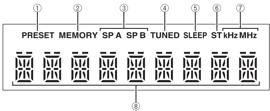
① PRESET indicator
| Indicator | Status |
| lights up | Recalling a preset radio station. |
| Searching an FM/AM station manually to register as a preset. | |
| blinks | Scanning for FM stations automatically to register as presets. |
② MEMORY indicator
| Indicator | Status |
| lights up | Registering an FM/AM station as a preset has been completed. |
| blinks | Searching an FM/AM station manually to register as a preset. |
| Scanning for FM stations automatically to register as presets. |
③ SP (SPEAKERS) A/B indicators
Light up according to the set of speakers selected. Both indicators light up when both sets of speakers are selected.
④ TUNED indicator
Lights up when this unit is tuned in to an FM or AM station with a strong signal.
⑤ SLEEP indicator
Lights up when the sleep timer is turned on (see page 13).
⑥ ST indicator
Lights up when this unit is in stereo mode and tuning in an FM station with a stereo broadcast.
⑦ kHz/MHz indicators
Lights up according to the current broadcast frequency.
kHz: AM
MHz: FM
⑧ Multi-information display
Shows information when adjusting or changing settings.
Rear panel
flowchart
graph TD
    A["Antenna"] --> B["FM 75Ω AM"]
    B --> C["CD"]
    C --> D["LINE"]
    D --> E["SPEAKERS"]
    E --> F["VOLTAGE SELECTOR 110-120 V 220-240 V"]
    C --> G["CD L"]
    C --> H["LINE L"]
    C --> I["3 PB REC L"]
    E --> J["SPEAKERS A B"]
    style A fill:#f9f,stroke:#333
    style B fill:#ccf,stroke:#333
    style C fill:#cfc,stroke:#333
    style D fill:#fcc,stroke:#333
    style E fill:#cff,stroke:#333
    style F fill:#ffc,stroke:#333
    style G fill:#cfc,stroke:#333
    style H fill:#fcc,stroke:#333
    style I fill:#cfc,stroke:#333
    style J fill:#fcc,stroke:#333
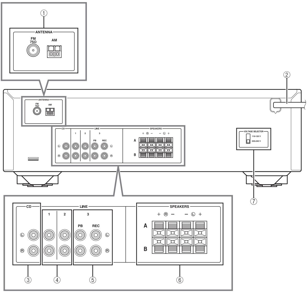
① ANTENNA terminals
Used to connect FM and AM antennas (see page 11).
② Power cable
For connecting this unit to an AC wall outlet (see page 11).
③ CD jacks
Used to connect a CD player (see page 9).
④ LINE 1-2 jacks
Used to connect audio components (see page 9).
⑤ LINE 3 jacks
PB (Playback) jacks
Used to connect to audio output jacks of an audio component.
REC (Recording) jacks
Used to connect to audio input jacks of an audio component.
⑥ SPEAKERS terminals
Used to connect speakers (see page 9).
⑦ VOLTAGE SELECTOR (Only for General model)
Remote control
flowchart
graph TD
    A["1"] --> B["SLEEP"]
    C["2"] --> D["LINE 1"]
    E["3"] --> F["LINE 2"]
    G["4"] --> H["LINE 3"]
    I["5"] --> J["TURING"]
    K["6"] --> L["TREBLE"]
    M["7"] --> N["BASS"]
    O["8"] --> P["L"]
    Q["9"] --> R["BALANCE"]
    S["10"] --> T["VOLUME"]
    U["11"] --> V["A"]
    W["12"] --> X["MUTE"]
    Y["13"] --> Z["ENTER"]
    AA["14"] --> AB["MEMORY"]
    AC["15"] --> AD["DISC SKIP"]
    AE["YAMAHA"]
■ Common controls
The following parts and controls can be used no matter which input source is selected.
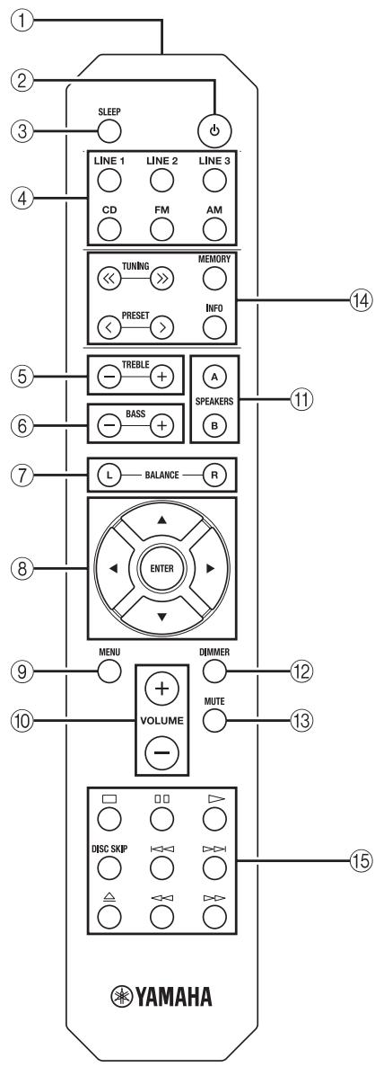
① Infrared signal transmitter
Sends infrared signals.
② ⏻ (power)
Turns this unit on, or sets it to standby mode.
③ SLEEP
Sets the sleep timer (see page 13).
④ Input selector buttons
Select the input source you want to listen to.

- The input source names correspond to the names of the connection jacks on the rear panel.
- To select TUNER as the input source using the remote control, press FM or AM.
⑤ TREBLE -/+
Increases or decreases the high frequency response. Control range: -10 dB to +10 dB
⑥ BASS -/+
Increases or decreases the low frequency response. Control range: -10 dB to +10 dB
⑦ BALANCE L/R
Adjusts the sound output balance of the left and right speakers to compensate for sound imbalances. Control range:

The opposite side of channel is muted.
The opposite side of channel is muted.
⑧ △ / ∇ / ◀ / ▷ / ENTER
Selects and confirms items in the Option menu (see page 19).
⑨ MENU
Turns the Option menu on and off (see page 19).
⑩ VOLUME +/-
Increases or decreases the sound output level.
⑪ SPEAKERS A/B
Turns on or off the speaker set connected to the SPEAKERS A and/or SPEAKERS B terminals on the rear panel each time the corresponding button is pressed (see page 12).
⑫ DIMMER
Select the brightness level of the front panel display from 3 levels by pressing this button repeatedly.

- This setting is retained even if you turn off this unit.
- The default setting is the brightest.
⑬ MUTE
Mutes the sound output. Press again to restore the sound output to the previous volume level.
■ FM/AM controls
The following buttons can be used when TUNER is selected as the input source.
⑭ TUNING << / >>
Selects the tuning frequency (see page 14).
PRESET
Selects a preset FM/AM station (see page 16).
MEMORY
Stores the current FM/AM station as a preset (see page 15).
INFO
Only for Europe model:
Switches information shown on the front panel display (see page 18).
■ Yamaha CD player controls
The following buttons can be used to control a Yamaha CD player.
⑮ Yamaha CD player control buttons
| ☐ | Stops playback |
| ☐☐ | Pauses playback |
| ▷ | Starts playback |
| DISC SKIP | Skips to the next disc in a CD changer |
| ◀◀ | Skips backward |
| ▷▷ | Skips forward |
| ≡ | Ejects the disc |
| ◀◀ | Rewinds playback |
| ▷▷ | Fast-forwards playback |
Note
Even when using a Yamaha CD player, certain components and features may not be available. Refer to your component's owner's manual for more information.
Using the remote control
■ Installing batteries
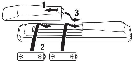
text_image
1 2 3AA, R6, UM-3 batteries
■ Operation range
Point the remote control at the remote control sensor on this unit and remain within the operating range shown below.
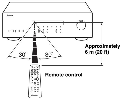
text_image
Approximately 6 m (20 ft) 30° 30° Remote control■ Notes on remote control and batteries
- The area between the remote control and this unit must be clear of large obstacles.
- Be careful not to spill water or other liquids on the remote control.
- Be careful not to drop the remote control.
- Do not leave or store the remote control in the following conditions:
– places of high humidity, such as near a bathroom
– places of high temperatures, such as near a heater or stove
– places of extremely low temperatures
- dusty places
- Change all batteries if you notice the operation range of the remote control narrows.
- If the batteries run out, immediately remove them from the remote control to prevent an explosion or acid leak.
- If you find leaking batteries, discard the batteries immediately, taking care not to touch the leaked material. If the leaked material comes into contact with your skin or gets into your eyes or mouth, rinse it away immediately and consult a doctor. Clean the battery compartment thoroughly before installing new batteries.
- Do not use old batteries together with new ones. This may shorten the life of the new batteries or cause old batteries to leak.
- Do not use different types of batteries (such as alkaline and manganese batteries) together. Batteries that look the same may have a different specification.
- Before inserting new batteries, wipe the battery compartment clean.
- Dispose of batteries according to your regional regulations.
- Keep the batteries in a location out of reach of children.
Batteries can be dangerous if a child were to put in his or her mouth.
- If you plan not to use this unit for a long period of time, remove the batteries from this unit. Otherwise, the batteries will wear out, possibly resulting in a leakage of battery liquid that may damage this unit.
CONNECTIONS
Connecting speakers and source components
Make sure to connect L (left) to L, R (right) to R, “+” to “+” and “−” to “−”. If the connections are faulty, no sound will be heard from the speakers, and if the polarity of the speaker connections is incorrect, the sound will be unnatural and lack bass. Refer to the owner’s manual for each of your components.
Make sure to use RCA cables to connect audio components.
CAUTION
- Do not connect this unit or other components to the main power until all connections between components are complete.
- Do not let bare speaker wires touch each other or any metal part of this unit. This could damage this unit and/or the speakers.
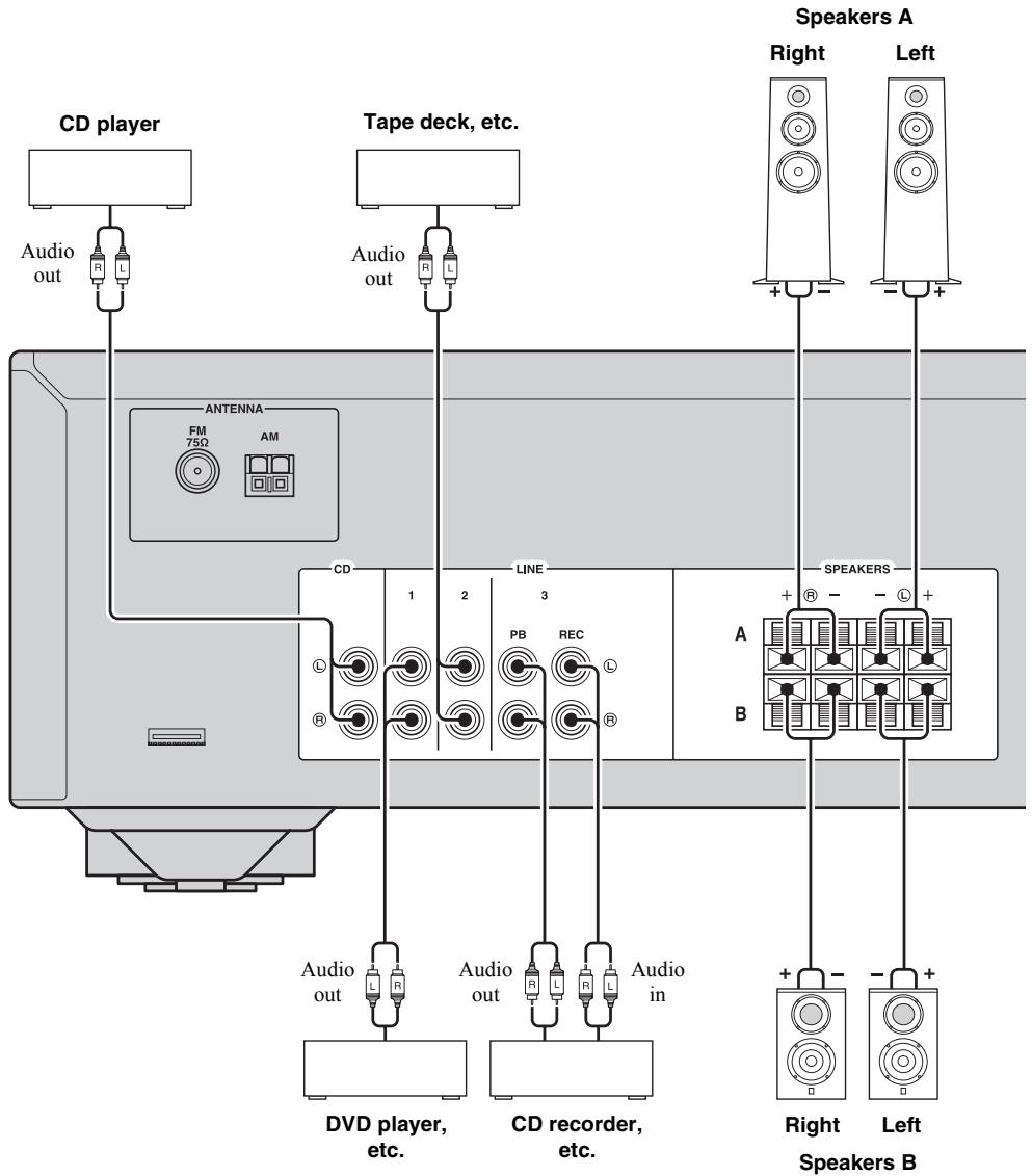
flowchart
graph TD
    A["CD player"] --> B["Audio out"]
    B --> C["Tape deck, etc."]
    C --> D["Antenna FM 750 AM"]
    D --> E["CD"]
    E --> F["Line"]
    F --> G["Speaker A Right"]
    F --> H["Speaker A Left"]
    I["DVD player, etc."] --> J["Audio out"]
    K["CD recorder, etc."] --> L["Audio in"]
    M["Speaker B"] --> N["Speaker A Right"]
    M --> O["Speaker A Left"]
■ REC jacks
- The REC jacks output audio signals of the currently selected input (except when LINE 3 is selected).
- Volume level, tone control and balance settings do not affect the REC jacks.
■ Connecting speaker cables
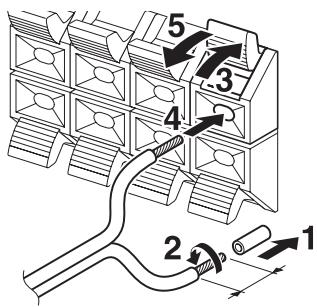
text_image
Technical diagram showing a mechanical assembly with numbered components and directional arrows indicating motion or flow.Remove approximately 10 mm (3/8 in) of insulation from the end of each speaker cable.
Note
When inserting speaker cables into the speaker terminals, insert only the bare speaker wire. If insulated cable is inserted, the connection may be poor and sound may not be heard.
CAUTION
Speaker impedance must be set as shown below.
| Speaker connection | Speaker impedance |
| SPEAKERS A or SPEAKERS B | 8 Ω or higher |
| SPEAKERS A and SPEAKERS B | 16 Ω or higher(except for North America model) |
| Bi-wiring | 8 Ω or higher |
■ Bi-wire connection
Bi-wire connection separates the woofer from the combined midrange and tweeter section.
A bi-wire compatible speaker has four binding post terminals. These two sets of terminals allow the speaker to be split into two independent sections. With these connections, the mid and high frequency drivers are connected to one set of terminals and the low frequency driver to another set of terminals.
Rear panel
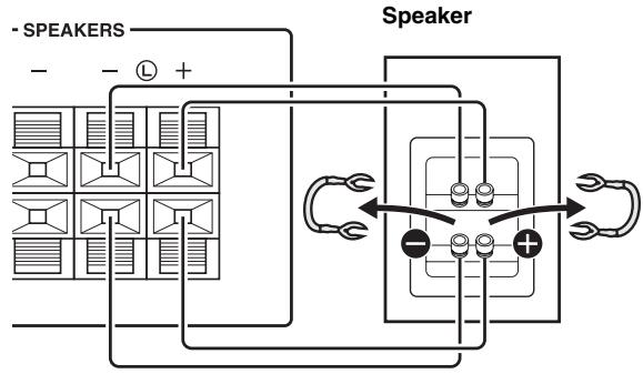
flowchart
graph TD
    A["Speaker"] --> B["Speaker"]
    B --> C["Speaker"]
    C --> D["Speaker"]
    D --> E["Speaker"]
    style A fill:#f9f,stroke:#333
    style B fill:#ccf,stroke:#333
    style C fill:#cfc,stroke:#333
    style D fill:#fcc,stroke:#333
Connect the other speaker to the other set of terminals in the same way.
Note
When making bi-wire connections, remove the shorting bridges or cables on the speaker.

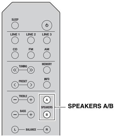
To use the bi-wire connections, press SPEAKERS A and SPEAKERS B so that both SP A and B light up on the front panel display.
text_image
SLEEP LINE 1 LINE 2 LINE 3 CD FM AM TUNING MEMORY PRESET INFO TREBLE A SPEAKERS A/B BASS B L BALANCE R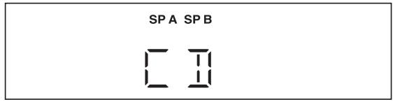
text_image
SP A SP B □ □Connecting the FM and AM antennas
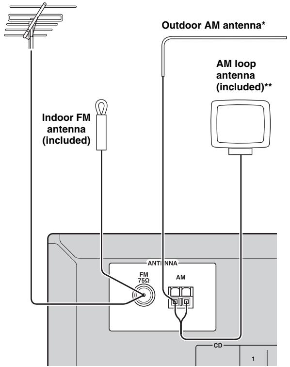
Indoor antennas for receiving FM and AM broadcasts are included with this unit. In general, these antennas should provide sufficient signal strength. Connect each antenna correctly to the designated terminals.
Note
If you experience poor reception quality, install an outdoor antenna. Consult the nearest authorized Yamaha dealer or service center about outdoor antennas.
Outdoor FM antenna
text_image
Outdoor AM antenna* Indoor FM antenna (included) AM loop antenna (included)** ANTI NNA FM 75Ω AM CD 1\*Outdoor AM antenna
Use 5 to 10 m of vinyl-covered wire extended outdoors from a window.
\*\*AM loop antenna (included)
- The AM loop antenna should always be connected, even if an outdoor AM antenna is connected to this unit.
- The AM loop antenna should be placed away from this unit.
- The wires of the AM antenna have no polarity.
■ Assembling the supplied AM loop antenna
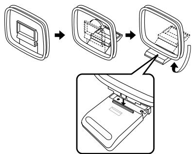
flowchart
graph TD
    A["Opening Window"] --> B["Cut Outer Box"]
    B --> C["Close Outer Box"]
    C --> D["Pressing Pin"]
    D --> E["Final Component"]
■ Connecting the wire of the AM loop antenna
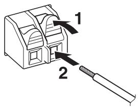
text_image
Diagram showing a device with labeled parts 1 and 2, indicating a process or assembly step.Connecting power cable
Plug the power cable into an AC wall outlet after all other connections are complete.
CAUTION
Only for General model:
Before connecting the power cable, make sure you set VOLTAGE SELECTOR of this unit according to your local voltage. Improper setting of VOLTAGE SELECTOR may cause fire and damage to this unit.
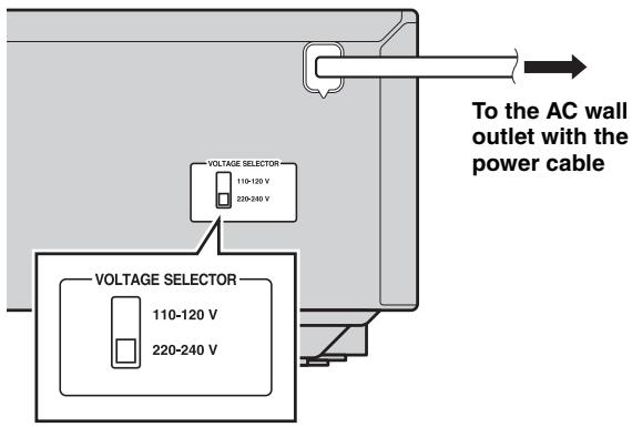
text_image
To the AC wall outlet with the power cable VOLTAGE SELECTOR 110-120 V 220-240 V VOLTAGE SELECTOR 110-120 V 220-240 VPlaying a source
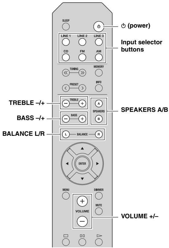
text_image
SLEEP LINE 1 LINE 2 LINE 3 CD FM AM TUNING MEMORY PRESET INFO TREBLE -/+ A SPEAKERS A/B BASS -/+ BASS B BALANCE L/R L BALANCE R ENTER MENU DIMMER VOLUME MUTE (VOLUME +/-)1 Press ⏻ (power) to turn on this unit.
2 Press one of the Input selector buttons to select the desired input source.
3 Press SPEAKERS A and/or SPEAKERS B to select desired speaker(s).
Notes
- When one set of speakers is connected using bi-wire connections, or when using two sets of speakers simultaneously (A and B), make sure SP A and SP B are displayed on the front panel display.
- When listening with headphones, turn off the speakers.
4 Play the source.
5 Press VOLUME +/- to adjust the sound output level.

You can adjust the tonal quality by using BASS - / + and TREBLE - / + , and the left/right sound balance of speakers by using BALANCE L/R (see page 6).
6 When finished listening, press ⏻ (power) to set this unit to standby mode.
Press ⏻ (power) to turn this unit on again.

- You can also use the buttons or knobs on the front panel if they have the same or similar names as those on the remote control.
- For recording, see page 5.
Using the sleep timer
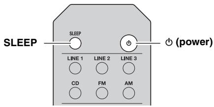
Use this feature to automatically set this unit to standby mode after a certain amount of time. The sleep timer is useful when you are going to sleep while this unit is playing or recording a source.
text_image
SLEEP SLEEP LINE 1 LINE 2 LINE 3 CD FM AM (POWER)Press SLEEP repeatedly to set the amount of time before this unit is set to standby mode.
Each time you press SLEEP, the front panel display changes cyclically as shown below.
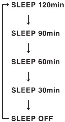
flowchart
graph TD
    A["SLEEP 120min"] --> B["SLEEP 90min"]
    B --> C["SLEEP 60min"]
    C --> D["SLEEP 30min"]
    D --> E["SLEEP OFF"]
The SLEEP indicator blinks while setting the amount of time for the sleep timer.
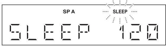
text_image
SP A SLEEP 128If the sleep timer is set, the SLEEP indicator on the front panel display lights up.

To cancel the sleep timer, do one of the following:
- Select "SLEEP OFF".
- Set this unit to standby mode.
FM/AM TUNING
Notes
- The radio frequencies differ depending on the country or region where this unit is being used. Front panel display illustrations shown in this section are based on Europe model.
- Only for Asia and General models:
Be sure to set the tuner frequency step according to the frequency spacing in your area before you tune into a radio station (see page 19).
text_image
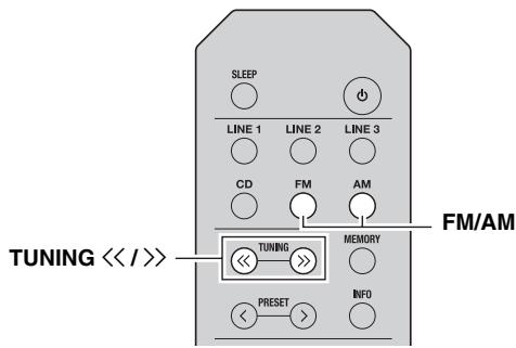
SLEEP LINE 1 LINE 2 LINE 3 CD FM AM TUNING << / >> TUNING MEMORY PRESET INFO FM/AM1 Press FM/AM to select TUNER as the input source and select the band.
2 Press and hold TUNING << / >> to begin tuning.
Press >> to tune in to a higher frequency.
Press << to tune in to a lower frequency.
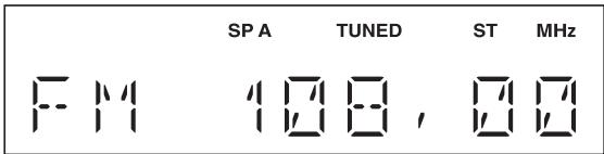
When this unit tunes in to a station, the TUNED indicator lights up on the front panel display.
text_image
SP A TUNED ST MHz FM 100, 100Note
If the tuning search does not stop at the desired station because the station signals are weak, press TUNING << / >> repeatedly to tune in to the desired station.

You can also use the buttons on the front panel if they have the same or similar names as those on the remote control.
■ Improving FM reception
If the signal from the station is weak and the sound quality is not good, set the FM band reception mode to monaural mode to improve reception.
Front panel
Press FM MODE, and then make sure the ST indicator is turned off (see page 4).
Remote control
Enter FM MODE from the Option menu to select MONO (monaural mode) (see page 19).
Using preset functions
You can register up to 40 radio stations as presets. Once you have registered stations, you can easily tune in to them by recalling the presets.
■ Presetting stations automatically (FM stations only)
You can automatically register FM stations that have strong signals.
Notes
- If a station is registered to a preset number that already has a station registered to it, the previously registered station is overwritten.
- If the station you want to store is weak in signal strength, press TUNING << / >> repeatedly to tune in to the desired station.
- Only for Europe model:
Only Radio Data System broadcasting stations can be preset automatically.

FM stations registered as presets using the automatic preset registration feature will be heard in stereo.
text_image
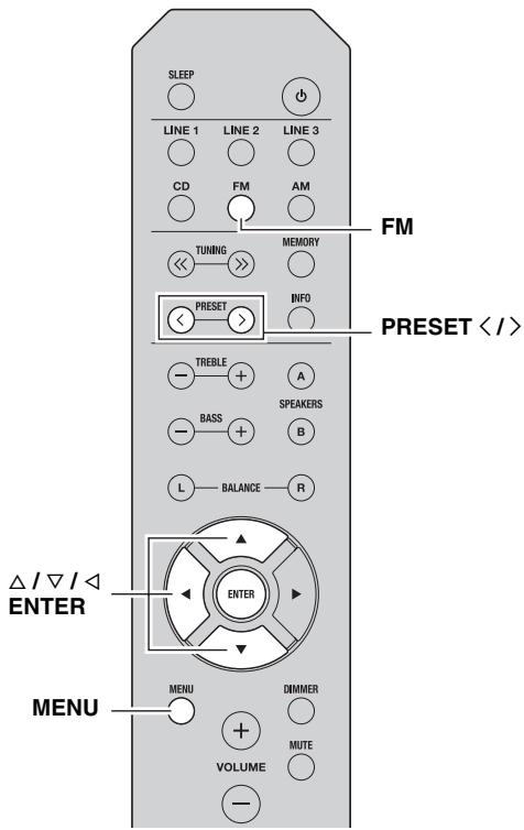
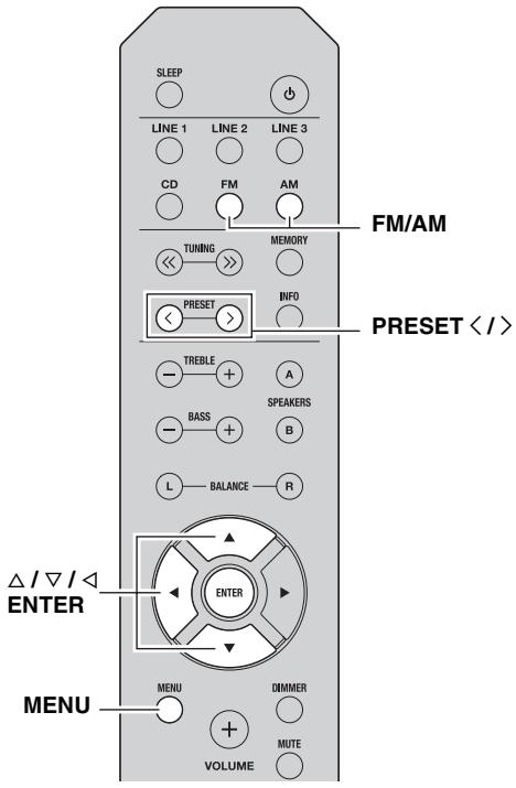
SLEEP LINE 1 LINE 2 LINE 3 CD FM AM TUNING MEMORY PRESET INFO TREBLE A BASS SPEAKERS L BALANCE R Δ / ∇ / ◀ ENTER MENU DIMMER VOLUME MUTE -1 Press FM to select TUNER as the input source.
2 Press MENU to enter the Option menu.
The Option menu for TUNER is displayed (see page 19).
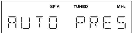
3 Press / to select “AUTO PRESET”, and then press ENTER.
text_image
SP A TUNED MHz AUTO PRESThis unit starts scanning the FM band about
3 seconds later from the lowest frequency upwards.

- Before scanning begins, you can specify the first preset number to be used by pressing PRESET < / > or / .
- To cancel scanning, press ◀.
text_image
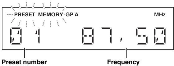
PRESET MEMORY CP A MHz 0 1 87, 50 Preset number FrequencyWhen a station to preset is found, information is displayed on the front panel display as shown in the illustration above.
When scanning is complete, “FINISH” is displayed, and then the display returns to the Option menu.
To return the display to the original state, press MENU.
■ Presetting stations manually
You can manually register the desired radio stations.
text_image
SLEEP LINE 1 LINE 2 LINE 3 CD FM AM TUNING MEMORY PRESET INFO TREBLE A MEMORY PRESET <| / >1 Tune in to the desired FM/AM station.
See page 14 for tuning instructions.
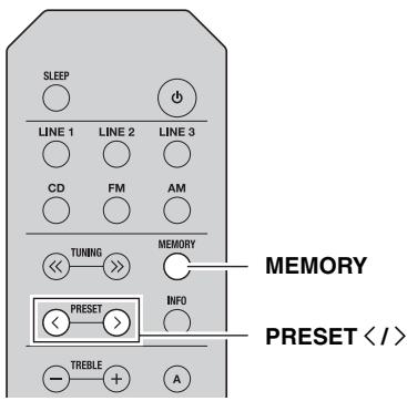
2 Press MEMORY.
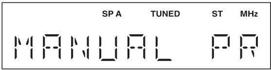
“MANUAL PRESET” is displayed briefly on the front panel display, and then the preset number to which the station will be registered is displayed.
text_image
SP A TUNED ST MHz MANUAL PR
By holding down MEMORY for more than 2 seconds, you can skip the following steps and automatically register the selected station to an empty preset number (i.e., the preset number following the last preset number used).
3 Press PRESET </> to select the preset number to which the station will be registered.
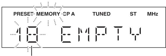
When you select a preset number to which no station is registered, “EMPTY” is displayed. When you select a preset number to which a station has already been registered, the frequency of the station is displayed.
text_image
PRESET MEMORY CP A TUNED ST MHz 10 EMPTYPreset number
4 Press MEMORY.
When registration is complete, the display returns to the original state.

- To cancel registration, switch input or band or do not perform any operations for about 30 seconds.
- You can also preset stations manually by pressing buttons on the front panel with the same names as remote control.
■ Recalling a preset station
You can recall preset stations that were registered by presetting automatically or manually.

text_image
SLEEP LINE 1 LINE 2 LINE 3 CD FM AM TUNING MEMORY PRESET > INFO TREBLE + A FM/AM PRESET < / >1 Press FM/AM to select TUNER as the input source.
2 Press PRESET < / > to select a preset number.
#
- Preset numbers to which no stations are registered are skipped.
- If this unit does not have any preset stations, “NO PRESET” is displayed.
- If the station signals that you want to recall are weak, try tuning in to a station manually.
- You can also recall a preset station by pressing PRESET < / > on the front panel.
■ Clearing a preset station
Follow the steps below to clear a preset station.
text_image
SLEEP LINE 1 LINE 2 LINE 3 CD FM AM TUNING MEMORY PRESET INFO TREBLE A SPEAKERS BASS B L BALANCE R Δ / ∇ / ◀ ENTER MENU DIMMER VOLUME MUTE FM/AM PRESET < / >1 Press FM/AM to select TUNER as the input source.
2 Press MENU to enter the Option menu.
The Option menu for TUNER is displayed (see page 19).
3 Press / to select “CLEAR PRESET”, and then press ENTER.
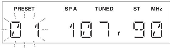
4 Select the desired preset station number by pressing / repeatedly.
The selected preset number blinks on the front panel display.
text_image
PRESET SP A TUNED ST MHz 0 1 10 7 , 9 8#
- You can also use PRESET < / > instead.
- To cancel clearing the preset station, press ◀ or leave this unit without any operations for about 30 seconds.
5 Press ENTER again to confirm.
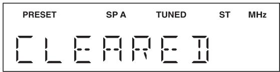
“CLEARED” is displayed on the front panel display. Then, another preset station is shown on the front panel display. When there is no more preset station, “NO PRESET” is displayed, and then the display returns to the Option menu.
To return the display to the original state, press MENU.
■ Clearing all preset stations
Follow the steps below to clear all preset stations.

text_image
SLEEP LINE 1 CD LINE 2 FM FM/AM LINE 3 AM TUNING MEMORY PRESET INFO TREBLE A BASS SPEAKERS L BALANCE R Δ / ∇ / ◀ ENTER MENU DIMMER VOLUME MENU MUTE1 Press FM/AM to select TUNER as the input source.
2 Press MENU to enter the Option menu.
The Option menu for TUNER is displayed (see page 19).
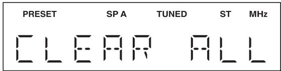
3 Press / to select “CLEAR ALL PRESET”, and then press ENTER.
text_image
PRESET SP A TUNED ST MHz CLEAR ALL
To cancel the operation and return to the Option menu, press ◀.
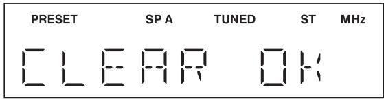
4 Press / to select “CLEAR OK”, and then press ENTER.
text_image
PRESET SP A TUNED ST MHz CLEAR OK
To cancel without clearing the presets, select "CLEAR NO".
When all presets have been cleared, “CLEARED” is displayed, and then the display returns to the Option menu.
To return the display to the original state, press MENU.
text_image
PRESET SP A TUNED ST MHz C L E A R E IReceiving Radio Data System information (Only for Europe model)
Radio Data System is a data transmission system used by FM stations in many countries.
text_image
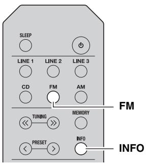
SLEEP LINE 1 LINE 2 LINE 3 CD FM AM TUNING MEMORY PRESET INFO INFO FM1 Press FM to select TUNER as the input source.
2 Tune in to the desired Radio Data System broadcasting station.
3 Press INFO repeatedly to select the desired Radio Data System display mode.
| Choice | Description |
| Frequency | This unit displays the frequency of the current station. |
| Program Service | Default setting. This unit displays the name of the Radio Data System program currently being received. |
| Program Type | This unit displays the type of the Radio Data System program currently being received. |
| Radio Text | This unit displays about the Radio Data System program currently being received. |
| Clock Time | This unit displays the current time being received. |
When you select Program Type, the following program types can be displayed.
| Program type | Description |
| NEWS | News |
| AFFAIRS | Current affairs |
| INFO | General information |
| SPORT | Sport |
| EDUCATE | Education |
| DRAMA | Drama |
| CULTURE | Culture |
| SCIENCE | Science |
| VARIED | Light entertainment |
| POP M | Popular music |
| ROCK M | Rock music |
| EASY M | Middle-of-the-road music (easy listening) |
| LIGHT M | Light classics |
| CLASSICS | Serious classics |
| OTHER M | Other music |
SETTING THE OPTION MENU FOR EACH INPUT SOURCE
The Option menu allows you to configure various settings for each input source and recall those settings automatically when an input source is selected.
text_image
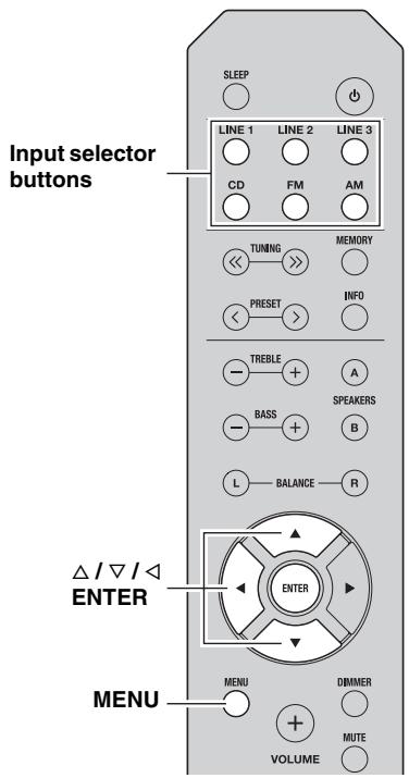
Input selector buttons SLEEP LINE 1 LINE 2 LINE 3 CD FM AM TUNING MEMORY PRESET INFO TREBLE A BASS SPEAKERS L BALANCE R △/▽/△ ENTER MENU DBMMER VOLUME MUTE1 Press one of the Input selector buttons to select the desired input source.
2 Press MENU.
3 Press / to select the desired menu item, and then press ENTER.
4 Press / to change the settings.
- For certain menu items, you must press ENTER to save the new setting.
- To return to the screen where you can select menu items, press ◀.
5 To exit the Option menu, press MENU.

Option menu items
Available menu items vary depending on the selected input source.
| Menu item | Description |
| MAX VOL | Sets the maximum volume level so that the volume will not be accidentally increased above a certain level.Adjustable range: 01 to 99, MAX* |
| INITIAL VOLUME (INIT VOL) | Sets the volume at the time this unit is turned on. When this parameter is set to “OFF”, the volume level used when this unit was set to standby is applied.Adjustable range: OFF*, MUTE, 01 to 99, MAX |
| TUNER STEP (TUNER STP)Only for Asia and General models | Sets tuner frequency step.Choices: AM10/FM100, AM9/FM50* |
| FM MODE | Changes the FM radio wave reception mode (see page 14).Choices: STEREO*, MONO |
| AUTO PRESET (A, PREST) | Automatically detects FM radio stations and registers them as preset stations (see page 14). |
| CLEAR PRESET (C, PREST) | Clears a selected preset station (see page 16). |
| CLEAR ALL PRESET (C,A, PREST) | Clears all preset stations (see page 17). |
| AUTO POWER STANDBY(AUTO STBY) | Sets this unit to standby mode automatically if no operation is performed in the specified time.Choices: OFF/2H/4H/8H*/12H |

The default settings are marked with “*”.
TROUBLESHOOTING
Refer to the chart below if this unit does not function properly. If the problem you are experiencing is not listed below or if the instructions below do not help, set this unit to standby mode, disconnect the power cable, and then contact the nearest authorized Yamaha dealer or service center.
General
| Problem | Cause | Remedy | See page |
| This unit fails to turn on. | The power cable is not connected or the plug is not completely inserted. | Connect the power cable firmly. | — |
| The impedance setting of the connected speaker is too small. | Use speaker(s) with proper speaker impedance. | 10 | |
| The protection circuitry has been activated because of a short circuit, etc. | Check that the speaker wires are not touching each other and then turn the power of this unit back on. | 9 | |
| This unit has been exposed to a strong external electric shock (such as lightning or strong static electricity). | Set this unit to standby mode, disconnect the power cable, plug it back in after 30 seconds, then use it normally. | — | |
| No sound | Incorrect input or output cable connections. | Connect the cables properly. If the problem persists, the cables may be defective. | 9 |
| No appropriate input source has been selected. | Select an appropriate input source by pressing one of the Input selector buttons on the remote control (INPUT ◀/▷ or FM/AM on the front panel). | 12 | |
| The SPEAKERS A/B switches are not set properly. | Turn on the corresponding SPEAKERS A or SPEAKERS B. | 12 | |
| Speaker connections are not secure. | Secure the connections. | 9 | |
| Output has been muted. | Deactivate the mute function. | 6 | |
| The MAX VOL or INITIAL VOLUME setting is set too low. | Set the setting to a higher value. | 19 | |
| The component corresponding to the selected input source is turned off or is not playing. | Turn the component on and make sure it is playing. | — | |
| The sound suddenly goes off. | The protection circuitry has been activated because of a short circuit, etc. | Check that the speaker wires are not touching each other and then turn the power of this unit back on. | 9 |
| This unit has become too hot. | Make sure the openings on the top panel are not blocked. | — | |
| The AUTO POWER STANDBY or SLEEP function has set this unit to standby mode. | Change the AUTO POWER STANDBY setting to a longer setting or OFF from the Option menu by pressing MENU. | 19 | |
| Only the speaker on one side can be heard. | Incorrect cable connections. | Connect the cables properly. If the problem persists, the cables may be defective. | 9 |
| Incorrect setting for the BALANCE L/R setting. | Set the BALANCE L/R setting to the appropriate position. | 6 | |
| There is a lack of bass and no ambience. | The + and - wires are connected in reverse at the amplifier or the speakers. | Connect the speaker wires to the correct + and - phase. | 9 |
| A “humming” sound can be heard. | Incorrect cable connections. | Connect the audio plugs firmly. If the problem persists, the cables may be defective. | 9 |
| The volume level cannot be increased, or the sound is distorted. | The component connected to the LINE 3 PB/REC jacks of this unit is turned off. | Turn on the power of the component. | — |
| The sound is degraded when listening with headphones connected to a CD player connected to this unit. | This unit has been set to standby mode. | Turn on the power of this unit. | 12 |
| The remote control does not work nor function properly. | Wrong distance or angle. | The remote control will function within a maximum range of 6 m (20 ft) and no more than 30 degrees off-axis from the front panel. | 8 |
| Direct sunlight or lighting (from an inverter type of fluorescent lamp, etc.) is striking the remote control sensor of this unit. | Reposition this unit. | — | |
| The batteries are weak. | Replace all batteries. | 8 | |
| Your CD player cannot be operated with the remote control. | The remote control does not support the CD player. | Refer to the owner's manual supplied with the CD palyer. | — |
| “OVER HEAT” appears on the front panel display. | This unit has become too hot. | Make sure the openings on the top panel are not blocked. | — |
| “CHECK SP” appears on the front panel display. | Speaker cables got shorted out. | Twist bare wires of speaker cables firmly, and then connect to this unit and speakers properly. | — |
Tuner
| Problem | Cause | Remedy | See page | |
| FM | FM stereo reception is noisy. | The particular characteristics of the FM stereo broadcasts being received may cause this problem when the transmitter is too far away or the antenna input is poor. | Check the antenna connections.Try using a high-quality directional FM antenna. | 11 |
| Switch to monaural mode. | 14 | |||
| There is distortion, and clear reception cannot be obtained even with a good FM antenna. | There is multipath interference. | Adjust the antenna position to eliminate the multipath interference. | — | |
| The desired station cannot be tuned in automatically. | The signal is too weak. | Try using a high-quality directional FM antenna. | 11 | |
| Try tuning manually. | 14 | |||
| FM/AM | “NO PRESET” is displayed. | No preset stations are registered. | Register stations you want to listen to as preset stations before operation. | 14 |
| AM | The desired station cannot be tuned in automatically. | The signal is weak or the antenna connections are loose. | Tighten the AM loop antenna connections and orient it for the best reception. | — |
| Try tuning manually. | 14 | |||
| Automatic station preset does not work. | Automatic station preset is not available for AM stations. | Use manual station preset. | 15 | |
| There are continuous crackling and hissing noises. | The noises may result from lightning, fluorescent lamps, motors, thermostats or other electrical equipment. | Try using an outdoor antenna and a earth ground.This will help somewhat, but it is difficult to eliminate all noise. | — | |
| There are buzzing and whining noises. | A TV set is being used nearby. | Move this unit away from the TV set. | — | |
SPECIFICATIONS
AUDIO SECTION
• Minimum RMS output power
(8 Ω, 40 Hz to 20 kHz, 0.2% THD)
[North America, General, Australia and Europe models]
.... 100 W + 100 W
[Asia model] .... 85 W + 85 W
- Input sensitivity/Input impedance (1 kHz, 100 W/8 Ω)
CD, etc. 500 mV/47 kΩ
- Output level/Output impedance
CD, etc. (Input 1 kHz, 500 mV)
REC 500 mV/2.2 kΩ
CD, etc. (Input 1 kHz, 500 mV, 8 Ω)
PHONES 470 mV/470 Ω
• Frequency response
CD, etc. (20 Hz to 20 kHz) 0 ± 0.5 dB
CD, etc. (10 Hz to 100 kHz) 0 ± 3.0 dB
• Total harmonic distortion
CD, etc. to SPEAKERS
(20 Hz to 20 kHz, 50 W, 8 Ω) 0.2% or less
• Signal to noise ratio (IHF-A network)
CD, etc. (500 mV input shorted) 100 dB or more
- Residual noise (IHF-A network) 70 V
- Tone control characteristics
BASS
Boost/Cut (50 Hz) ± 10 dB
TREBLE
Boost/Cut (20 kHz) .... ± 10 dB
FM SECTION
-
Tuning range
[North America model] 87.5 to 107.9 MHz
[Asia and General models] ..... 87.5 to 107.9 MHz/87.50 to 108.00 MHz
[Australia and Europe models] 87.50 to 108.00 MHz -
50 dB quieting sensitivity (IHF, 1 kHz, 100% MOD.)
Mono 3.0 μV (20.8 dBf)
• Signal to noise ratio (IHF)
Mono/Stereo 72 dB/70 dB
• Harmonic distortion (1 kHz)
Mono/Stereo 0.3%/0.5% - Antenna Input.... 75 Ω, unbalanced
AM SECTION
- Tuning range
[North America model] 530 to 1710 kHz
[Asia and General models] ..... 530 to 1710 kHz/531 to 1611 kHz
[Australia and Europe models] 531 to 1611 kHz
GENERAL
-
Power supply
[North America model] ...... AC 120 V, 60 Hz
[General model] ...... AC 110-120/220-240 V, 50/60 Hz
[Australia model] AC 240 V, 50 Hz
[Europe model] ...... AC 230 V, 50 Hz
[Asia model] AC 220-240 V, 50/60 Hz -
Power consumption
[North America, General, Australia and Europe models] 175 W
[Asia model] 140 W -
Standby power consumption
[North America, Australia, Europe and Asia models] 0.5 W or less
- Dimensions (W × H × D) .... 435 × 141 × 322 mm (17'1/8" × 5'1/2" × 12'5/8")
- Weight 6.7 kg (14.8 lbs)
* Specifications are subject to change without notice.
Information for Users on Collection and Disposal of Old Equipment and Used Batteries

These symbols on the products, packaging, and/or accompanying documents mean that used electrical and electronic products and batteries should not be mixed with general household waste.
For proper treatment, recovery and recycling of old products and used batteries, please take them to applicable collection points, in accordance with your national legislation and the Directives 2002/96/EC and 2006/66/EC.
By disposing of these products and batteries correctly, you will help to save valuable resources and prevent any potential negative effects on human health and the environment which could otherwise arise from inappropriate waste handling.
For more information about collection and recycling of old products and batteries, please contact your local municipality, your waste disposal service or the point of sale where you purchased the items.
[Information on Disposal in other Countries outside the European Union]
These symbols are only valid in the European Union. If you wish to discard these items, please contact your local authorities or dealer and ask for the correct method of disposal.
Note for the battery symbol (bottom two symbol examples):
This symbol might be used in combination with a chemical symbol. In this case it complies with the requirement set by the Directive for the chemical involved.
Pb
ATTENTION : VEUILLEZ LIRE CE QUI SUIT AVANT D'UTILISER L'APPAREIL.
FONCTIONS UTILES....1
ACCESSOIRES FOURNIS....1
COMMANDES ET FONCTIONS....2
Panneau avant 2
Piles (× 2)
(AA, R6, UM-3)
Panneau avant
text_image
STANDBY/ON FM MODE MEMORY FM/AM < PRESET > << TUNING ># YAMAHA STANDBY/ON FM MODE MEMORY FM/AM < PRESET > << TUNING ># VOLUME PHONES SPEAKERS A B BASS TREBLE TNIPUT① ⏻ (alimentation)
text_image
Diagram showing a device with labeled parts 1 and 2, indicating a process or assembly step.text_image
SP A SLEEP 5 SLEEP 128text_image
SLEEP LINE 1 LINE 2 LINE 3 CD FM AM TUNING MEMORY PRESET INFO FM INFOtext_image
Technical diagram showing a mechanical assembly with numbered components and directional arrows indicating motion or flow.text_image
SP A SP B □ □text_image
Diagram showing a device with labeled parts 1 and 2, indicating a process or assembly step.text_image
SLEEP SLEEP LINE 1 LINE 2 LINE 3 CD FM AM (Netz)text_image
SP A SLEEP 5 SLEEP 120text_image
SP A TUNED ST MHz MANUAL P R#
text_image
SLEEP LINE 1 LINE 2 LINE 3 CD FM AM TUNING MEMORY PRESET INFO INFO FMtext_image
SP A SP B □ □text_image
Diagram showing a device with labeled parts 1 and 2, likely illustrating a mechanical or electrical component assembly.Ansluta nätkabeln
text_image
SPA SLEEP 5LEEP 128text_image
SLEEP LINE 1 LINE 2 LINE 3 CD FM AM TUNING MEMORY PRESET INFO INFO FMtext_image
Circa 6 m 30° 30° Telecomandotext_image
Technical diagram showing a mechanical assembly with numbered components and directional arrows indicating motion or force.flowchart
graph TD
    A["Component with monitor icon"] --> B["Add screen to screen"]
    B --> C["Add folder to laptop"]
    C --> D["Add folder to laptop"]
text_image
Diagram showing a device with labeled parts 1 and 2, indicating a component or assembly step.text_image
SPA SLEEP SLEEP SLEEP 120text_image
PRESET SP A TUNED ST MHz C L E A R E I- Dimensioni (L × A × P) 435 × 141 × 322 mm
- Peso 6,7 kg
text_image
Technical diagram showing a mechanical assembly with numbered components and directional arrows indicating motion or flow.text_image
SP A SP B □ □text_image
Diagram showing a device with labeled parts 1 and 2, indicating a process or assembly step.text_image
SP A SLEEP 5 SLEEP 128text_image
PRESET SP A TUNED ST MHz C L E A R E Itext_image
SLEEP LINE 1 CD FM AM TUNING MEMORY PRESET INFO FM INFOFM/AM AFSTEMMEN....14
text_image
SP A SP B □ □text_image
Diagram showing a device with labeled parts 1 and 2, indicating a process or assembly step.text_image
SP A SLEEP 5 SLEEP 128text_image
SLEEP LINE 1 LINE 2 LINE 3 CD FM AM TUNING MEMORY PRESET INFO FM INFOflowchart
graph TD
    A["Screen with logo"] --> B["Chip with internal structure"]
    B --> C["Device with internal structure"]
    C --> D["Clip with attached clip"]
    D --> E["Back panel with clipboard"]