
KSEV910X1 - Basket SMEG - Free user manual and instructions
Find the device manual for free KSEV910X1 SMEG in PDF.
| Product type | Range hood |
| Brand | SMEG |
| Model | KSEV910X1 |
| Power supply | 220-240 V ~ 50 Hz (check rating plate) |
| Installation types | Extraction version (external venting) or recirculation version (recycling with charcoal filter) |
| Minimum safety distance | 50 cm above an electric hob, 65 cm above a gas or mixed hob |
| Grease filter | Washable metal filter (dishwasher or hand wash) |
| Active charcoal filter | For recirculation version, cleanable or replaceable depending on model |
| Lighting | Halogen lamps 20 W max (G4) or other types depending on version (see manual) |
| Controls | Push buttons, electronic 5/6 keys, with display or with sensor depending on version |
| Suction speeds | Several speeds (1, 2, 3) + intensive speed (P) |
| Timer | Programmed automatic shut-off (20 min at speed 1, 15 min at speed 2, etc.) |
| Filter saturation indicator | Light signal for grease filter and/or charcoal filter (depending on version) |
| Automatic function (models with sensor) | Automatic vapor detection and speed adjustment |
| Telescopic chimney | Adjustable chimney to suit ceiling height |
| Maintenance | Regular cleaning of interior and exterior with a damp cloth and neutral detergent |
| Lamp replacement | Accessible depending on model (see manual for procedure) |
| Repairability | Spare parts available from after-sales service |
| Weight | Not specified in the manual |
Frequently Asked Questions - KSEV910X1 SMEG
User questions about KSEV910X1 SMEG
0 question about this device. Answer the ones you know or ask your own.
Ask a new question about this device
Download the instructions for your Basket in PDF format for free! Find your manual KSEV910X1 - SMEG and take your electronic device back in hand. On this page are published all the documents necessary for the use of your device. KSEV910X1 by SMEG.
USER MANUAL KSEV910X1 SMEG
EN - Instruction on mounting and use
Consult the designs in the front pages referenced in the text by alphabet letters.
Closely follow the instructions set out in this manual. All responsibility, for any eventual inconveniences, damages or fires caused by not complying with the instructions in this manual, is declined.
Use
The hood is designed to be used either for exhausting or filter version.
Ducting version
The hood is equipped with a top air outlet B for discharge of fumes to the outside (exhaust pipe and pipe fixing clamps not provided). Filter version
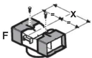
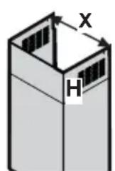
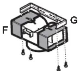
Should it not be possible to discharge cooking fumes and vapour to the outside, the hood can be used in the filter version, fitting an activated carbon filter and the deflector F on the support (bracket) G, fumes and vapours are recycled through the top grille H by means of an exhaust pipe connected to the top air outlet B and the connection ring mounted on the deflector F (exhaust pipe and pipe fixing clamps not provided).
The models with no suction motor only operate in ducting mode, and must be connected to an external suction device (not supplied).
Installation
The minimum distance between the supporting surface for the cooking vessels on the hob and the lowest part of the range hood must be not less than 50cm from electric cookers and 65cm from gas or mixed cookers.
If the instructions for installation for the gas hob specify a greater distance, this must be adhered to.

Electrical connection
The mains power supply must correspond to the rating indicated on the plate situated inside the hood. If provided with a plug connect the hood to a socket in compliance with current regulations and positioned in an accessible area. If it not fitted with a plug (direct mains connection) or if the plug is not located in an accessible area apply a bi-polar switch in accordance with standards which assures the complete disconnection of the mains under conditions relating to overcurrent category III, in accordance with installation instructions.
Warning: Before re-connecting the hood circuit to the mains supply and checking the efficient function, always check that the mains cable is correctly assembled.
Mounting
Expansion wall plugs are provided to secure the hood to most types of walls/ceilings. However, a qualified technician must verify suitability of the materials in accordance with the type of
wall/ceiling. The wall/ceiling must be strong enough to take the weight of the hood. Do not tile, grout or silicone this appliance to the wall. Surface mounting only.
Preliminary information for installation of the hood:
Disconnect the hood during electrical connection, by turning the home mains switch off.
Remove the fat/s filter/s and the carbon filter frame.
Do not tile, grout or silicone this appliance to the wall. Surface mounting only. Do not fix chimney flue to furniture or fly over shelves unless the chimney flue can be easily removed, in case maintenance is ever required.
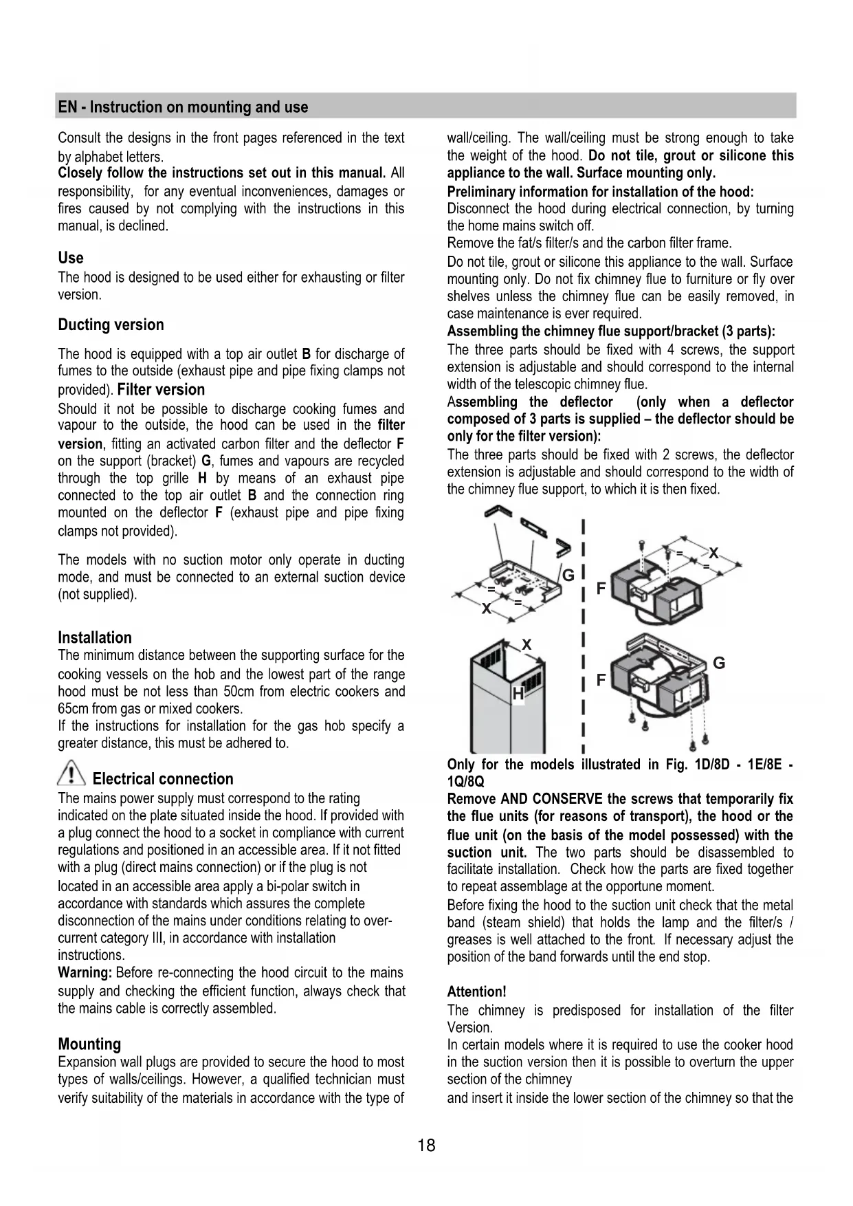
Assembling the chimney flue support/bracket (3 parts):
The three parts should be fixed with 4 screws, the support extension is adjustable and should correspond to the internal width of the telescopic chimney flue.
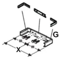
Assembling the deflector (only when a deflector composed of 3 parts is supplied - the deflector should be only for the filter version):
The three parts should be fixed with 2 screws, the deflector extension is adjustable and should correspond to the width of the chimney flue support, to which it is then fixed.
Only for the models illustrated in Fig. 1D/8D - 1E/8E - 1Q/8Q
Remove AND CONSERVE the screws that temporarily fix the flue units (for reasons of transport), the hood or the flue unit (on the basis of the model possessed) with the suction unit. The two parts should be disassembled to facilitate installation. Check how the parts are fixed together to repeat assemblage at the opportune moment.
Before fixing the hood to the suction unit check that the metal band (steam shield) that holds the lamp and the filter/s / greases is well attached to the front. If necessary adjust the position of the band forwards until the end stop.
Attention!
The chimney is predisposed for installation of the filter Version.
In certain models where it is required to use the cooker hood in the suction version then it is possible to overturn the upper section of the chimney
and insert it inside the lower section of the chimney so that the
air-exit perforations are not visible. The chimneys in which this operation is possible are recognizable by their bracket fixing points G which are repeated also in the lower side of the upper section of the chimney (see installation sequence 20a-20b).
Attention! for all pre-assembled models:
the mounting operations "1, 2, 3" should not be taken into consideration, for installation begin at operation "4".
- Rest the suction unit on a flat surface and thread the lower part of the hood onto it (consult the figure corresponding to the model in possession - Fig. 1C/8C - 1D/8D - 1I/8I - 1E/8E - 1F/8F - 1G/8G - 1H/8H - 1R/8R - 1N-1O-1P).
- Make all the electrical connections between the two parts (Fig. 9).
- Permanently fix the cooker hood to the suction group with the screws (consult the figure corresponding to the model in possession - Fig. 1C/8C - 1D/8D - 1I/8I - 1E/8E - 1F/8F - 1G/8G - 1H/8H - 1R/8R - 1N-1O-1P).
- Using a pencil, draw a line on the wall, extending up to the ceiling, to mark the centre. This will facilitate installation (Fig. 10).
- Rest the drilling template against the wall: the vertical centre line printed on the drilling template must correspond to the centre line drawn on the wall, and the bottom edge of the drilling template must correspond to the bottom edge of the hood: bear in mind that, when installation is complete, the underside of the hood must be at least 50~cm above the cooker top in the case of electric cookers, and at least 65~cm above the cooker top in the case of gas or mixed cookers.
- Place the lower support bracket on the perforation diagram making it coincide with the traced triangle, mark the two external holes and perforate. Remove the perforation diagram, insert two wall-dowels and fix the support bracket of the hood with two 5 × 45 ~mm screws (Fig. 10).
Attention: only the models illustrated in Fig. 1Q/10Q:
Fix the central bracket with two screws and wall-dowels above the lower bracket (see perforation diagram for positioning the holes).
- If supplied dismantled, fix the hooks to the side of the aspiration group with two screws (fig. 10a). Hang the hood onto the lower bracket.
- Adjust the distance of the hood from the wall.
- Adjust the horizontal position of the hood.
- Using a pencil mark the cooker hood permanent drill hole inside the suction group (1 or 2 fixing points are necessary for permanent mounting) (Fig. 11).
- Remove the hood from the lower bracket.
- Drill at the point marked ( 8mm) (Fig. 12).
- Insert 1 or 2 wall screw anchors according to requirement.
- Apply the flues support bracket "G" to the wall adherent to the ceiling, use the flues support bracket as a perforation diagram (if present, the small slot on the support must coincide with the line drawn previously on the wall) and mark two holes with a pencil. Make the holes ( 8mm)
and insert 2 dowels (Fig. 13).
- Fix the chimney support bracket to the wall using two 5 × 45 ~mm screws.
- Hook the hood onto the bottom bracket.
- Fix the hood into its final position on the wall (ABSOLUTELY ESSENTIAL) (Fig. 14).
- Connect a pipe (pipe and pipe clamps not provided, to be purchased separately) for discharge of fumes to the connection ring located over the suction motor unit.
If the hood is to be used in ducting version, the other end of the pipe must be connected to a device expelling the fumes to the outside. If the hood is to be used in filter version, then fix the deflector F to the chimney support bracket G and connect the other extremity of the pipe to the connection ring placed on the deflector F (Fig. 13-15).
19. Connect the electricity.
Attention: only the models illustrated in Fig. 1Q:
Continue from the installation sequence number 23.
20. Apply the chimney stacks and fasten them at the top to the chimney support „G“ (20b) using 2 screws (20a) (Fig. 16).
Only for model with optical fibers point lighting (Fig. 1G):
Check that the chimneys may be removed to permit access to the optical fibers lamp housing area.
Only for the model with control panel on chimney flue (Fig. 1L-17):
Insert the command plate from the motor group through the chimney flue slit from the inside towards the outside (20c).
Carry out the connection of the control panel to the command plate.
Attention! The terminal pivot on the plate MUST correspond to the drill hole on the connection block situated at the back of the control panel.
- Slide the bottom section of the chimney down until it completely covers the suction unit and slots into the housing provided on top of the hood (Fig. 18).
- Fix the lower section of the chimney with two screws (only for the model in Fig. 1H/19H-1J/19J-1L/19L-1M/19M-1N/19N-1O/19O-1P/19P).
23. Only the models illustrated in Fig. 1Q:
- Put the flues unit on the suction unit.
Connect the electricity between the two parts (Fig. 9).
Fix the flue units definitively to the suction unit with the screws (consult the figure corresponding to the model in possession) (Fig. 8Q).
Attention! Check that the lower section of the flue fits onto the central bracket (Fig. 20).
Fix the upper section of the flue units to the flues support bracket with two screws (Fig. 16).
Remount the carbon filter frame and the fat/s filter/s and check the perfect functioning of the hood.
Description of the hood
Fig. 1
- Control panel
- Grease filter
- Grease filter release handle
- Halogen lamp
- Vapour screen
- Telescopic chimney
- Air outlet (used for filter version only)
- point lighting (only for the model in Fig. 1G)
Operation
Use the high suction speed in cases of concentrated kitchen vapours. It is recommended that the cooker hood suction is switched on for 5 minutes prior to cooking and to leave in operation during cooking and for another 15 minutes approximately after terminating cooking.
Functioning - Model with Keyboard
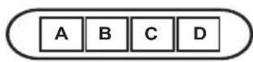
A. on/off light switch
B. on/off aspiration switch and minimum power selection
B+C. medium power selection aspiration switch
B+D. maximum power selection aspiration switch
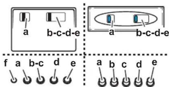
a. ON/OFF lighting
b. OFF motors
c. -d. - e. Minimum suction power (c.), medium (d.), maximum (e.).
f. Operation warning light (where present).
Note: Some models only possess one suction Power.
Attention: the models with an electric valve are supplied with 3 keys:
(a) Light ON/OFF, (b) Electric Valve Closure and (c) Opening.
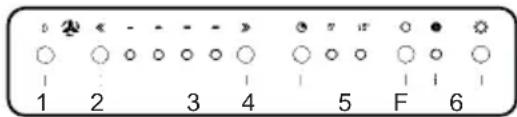
Functioning - 5-key electronic model
-
Motor OFF button
-
ON button and motor speed selection button 1 - 2 - 3 - 1 - 2 - .
-
Speed 1 LED
-
Speed 2 LED and metal grease filter saturation LED (in this latter case, the LED will flash - See instructions on grease filter cleaning).
Once the grease filters have been cleaned, press button 1 for about 3 seconds until you hear the acoustic signal (beep): the LED 4 will now stop flashing.
- Speed 3 LED and active carbon filter saturation LED (in this latter case, the LED will flash - See instructions on active carbon filter replacement).
Once you have replaced the charcoal filter, press button 1 for about 3 seconds until you hear the acoustic signal (beep). LED 5 will now stop flashing. Warning!
The active carbon filter saturation LED is not activated. In order to activate the active carbon filter saturation indicator, press buttons 2 and 7 simultaneously for 3 seconds. Initially, only LED 4 will flash, then after the 3 seconds have passed, LED 5 will also start flashing, indicating that the active carbon filter saturation control system is active.
To switch off the system, re-press the same two buttons: after 3 seconds LED 5 will stop flashing and the device will be switched off.
-
Intensive speed LED
-
Intensive speed ON switch
This speed should be used when the concentration of cooking fumes or odours is particularly strong (for example when frying, cooking fish etc.).
The fast speed will run for about 5 minutes and then return to the speed previously set automatically (1, 2 or 3), or switch off if no speed was selected.
To turn off the fast speed, before the end of the 5 minutes, press button 1 or button 2.
-
OFF lamp button
-
ON lamp button
If the hood fails to operate correctly, briefly disconnect it from the mains power supply for almost 5 sec. by pulling out the plug. Then plug it in again and try once more before contacting the Technical Assistance Service.
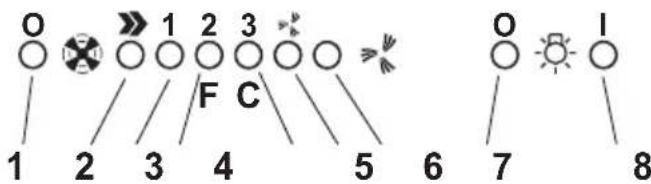
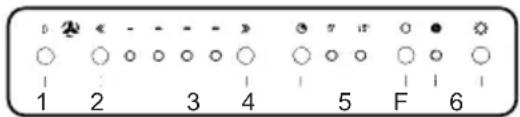
Functioning - Model with display


A. OFF key (Display off) /Stand-by (led lit on the display) - press for a long time to select the function desired.
B. Lighting, on/off.
C. Timer for selected speed (visualizes the speed selected and flashing LED on the lower side of the display). This knob permits the operation of the cooker hood for a established period:
20 minutes if the speed selected is 1
15 minutes if the speed selected is 2
10 minutes if the speed selected is 3
5 minutes if the intensive speed is selected.
D. Display showing:
Fan speed (1-3-P).
- Change grease filters (grease filter saturation indicator - F)
After washing the anti-grease filter, depress knob A for about 3 seconds. The letter F will disappear from the display.
- Change activated carbon filters (carbon filter saturation indicator - C).
After replacing the charcoal filter, depress knob A for about 3 seconds. The letter C will disappear from the display.
- When the led in the lower right side is on, it indicates that the cooker hood is ready for operation ("standby" position), the flashing LED indicates that the timer has been activated for selected speed.
Attention! The active carbon filter saturation indicator is normally deactivated, to activate it:
Set the hood on OFF (display off), press keys C and G contemporaneously for 3 secs.
Initially, only letter F will be displayed, then after the 3 seconds have passed, letter C will be displayed as well, indicating that the carbon filter saturation control system is active.
To switch off the system, re-press the same two buttons: letter C appear on display and after 3 seconds letter it disappear and the device will be switched off.
E. Knob to decrease the speed.
F. Knob to increase the speed.
G. Timed intensive speed button: the hood operates at this speed for 5 minutes and then returns to the previous settings. The display will show P and a blinking dot. This function can be cancelled by pressing button A.
If the hood fails to operate correctly, briefly disconnect it from the mains power supply for almost 5 sec. by pulling out the plug. Then plug it in again and try once more before contacting the Technical Assistance Service.
Warning! Always press the fan off button A before disconnecting the hood from the mains supply.
Functioning - Model with display

A - Lighting, on/off.
B - Fan off (Stand by)
C - Timer for selected speed (visualizes the speed selected and flashing LED on the lower side of the display).
This knob permits the operation of the cooker hood for a established period:
20 minutes if the speed selected is 1
15 minutes if the speed selected is 2
10 minutes if the speed selected is 3
5 minutes if the intensive speed P is selected.
D - Display showing:
Fan speed (1-3-P).
- Change grease filters (grease filter saturation indicator - F)
After washing the anti-grease filter, depress knob B for about 3 seconds. The letter F will disappear from the display.
- Change activated carbon filters (carbon filter saturation indicator - C).
After replacing the charcoal filter, depress knob B for about 3 seconds. The letter C will disappear from the display.
- When the led in the lower right side is on, it indicates that the cooker hood is ready for operation ("standby" position), the flashing LED indicates that the timer has been activated for selected speed.
Warning!
The active carbon filter saturation function is not activated. In order to activate the carbon filter saturation indicator, press buttons E and F simultaneously for 3 seconds. Initially, only letter F will be displayed, then after the 3 seconds have passed, letter C will be displayed as well, indicating that the carbon filter saturation control system is active.
To switch off the system, re-press the same two buttons: letter C appear on display and after 3 seconds letter it disappear and the device will be switched off.
E - Knob to decrease the speed: from intensive speed P to speed level 1.
F - Knob to increase (standby) speed to intensive speed P. Attention! Intensive speed P has a duration of 5 minutes after which the cooker hood automatically sets the speed to level 2 (suction power).
If the hood fails to operate correctly, briefly disconnect it from the mains power supply for almost 5 sec. by pulling out the plug. Then plug it in again and try once more before contacting the Technical Assistance Service.
Warning!
Always press the fan off button A before disconnecting the hood from the mains supply.
Functioning - 6-key electronic model
1-Motor OFF key.
2-Diminishes the speed.
3-Increases the speed.
4- 5/15 minutes timer. Inserts and extracts the timer.
The speed in function is turned off automatically.
5- Resets carbon filters saturation indicator.
When the F led lights up, the carbon filter should be cleaned or changed.
Press for at least 3 seconds after having changed the carbon filter. The F led will turn off to indicate the resetting of the saturation indicator.
Note: This led switches ON even if the carbon filter has not been mounted.
6-ON/OFF light.
If the hood fails to operate correctly, briefly disconnect it from the mains power supply for almost 5 sec. by pulling out the plug. Then plug it in again and try once more before contacting the Technical Assistance Service.
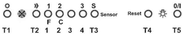
Electronic model with sensor
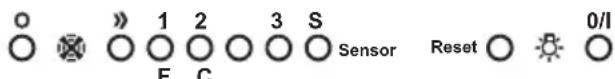
T1 T2 T3 T4 T5
T1. Hood On/Off key
T2. Increase cyclical motor speed key.
Pressing the first time activates speed 1. A Led (1-2-3), corresponding to each speed, switches on. Led 4 flashes at intensive speed.
After 5 minutes intensive speed is reduced to the second speed. If key T2 is pressed before the end of the 5 minutes, the hood retunes to the first speed.
T5. Lights On/Off key.
Filter signals
(function active with the hood on): the fats filter signal appears after 80 hours functioning (Led 1 flashing).
The carbon filter signal appears after 320 hours (Led 2 flashing). In the case of simultaneous signalling of the fats and carbon filters, Leds 1 and 2 flash alternatively.
Reset filter signals:
press key T4 for 3 seconds until Led 1 switches off (fats filter). In the case of both filters (fats and carbon) signalling, repeat the operation just described: pressing T4 the first time switches off LEDs 1 and 2 that are flashing alternatively. Immediately afterwards Led 2 flashes again: at this point press T4 again for 3 seconds. A beep signals each time the operation is completed.
Enabling the carbon filter signal:
the hood is enabled only for the fats filter signal. To enable
the carbon filter signal: hood in Off, press keys T2 and T4 for 3 seconds. The flashing of LEDs 1 and 2 signals the completion of the setting. To disenable the carbon filter signal, repeat this operation again (always with the hood in Off). A beep signals each time the operation is completed.
Automatic calibration:
the system carries calibration out automatically about every 30 minutes (calibration of the parameters functioning of the sensors).
Manual calibration:
with the hood in Off, press keys T3 and T4 until the beep.
Automatic functioning:
to activate automatic functioning, press key T3: Led 4 switches on. To return to manual functioning, press key T1, T2 or T3.
Sensors test:
this happens continuously during automatic functioning. In the case of damage all the LEDs flash: in this case, return to manual functioning, pressing keys T1, T2 or T3.
Selecting cooking top:
this operation optimises the automatic functioning of the hood: with the hood in Off press keys T2 and T3 for about 3 seconds until the cooking top at present in use is seen: gas top - Led 1 on
induction top - Led 2 on
electric top - Led 3 on.
Select the cooking top requested pressing T2, then press T2 and T3 simultaneously for three seconds until the Beep. Alt the end the hood switches off.
The gas top is the default state.
Attention: carry out this operation the first time the hood is switched on.
Maintenance
ATTENTION! Before performing any maintenance operation, isolate the hood from the electrical supply by switching off at the connector and removing the connector fuse.
Or if the appliance has been connected through a plug and socket, then the plug must be removed from the socket.
Cleaning
The cooker hood should be cleaned regularly (at least with the same frequency with which you carry out maintenance of the fat filters) internally and externally. Clean using the cloth dampened with neutral liquid detergent. Do not use abrasive products. DO NOT USE ALCOHOL!
Warning:
Failure to carry out the basic cleaning recommendations of the cooker hood and replacement of the filters may cause fire risks.
Therefore, we recommend oserving these instructions.
The manufacturer declines all responsibility for any damage to the motor or any fire damage linked to inappropriate maintenance or failure to observe the above safety recommendations.
Grease filter
Fig. 2
This must be cleaned once a month (or when the filter saturation indication system - if envisaged on the model in possession - indicates this necessity) using non aggressive detergents, either by hand or in the dishwasher, which must be set to a low temperature and a short cycle.
When washed in a dishwasher, the grease filter may discolour slightly, but this does not affect its filtering capacity.
To remove the grease filter B, pull the spring release handle.
Charcoal filter (filter version only)
Fig. 3
It absorbs unpleasant odours caused by cooking.
The charcoal filter can be washed once every two months (or when the filter saturation indication system - if envisaged on the model in possession - indicates this necessity) using hot water and a suitable detergent, or in a dishwasher at 65^ (if the dishwasher is used, select the full cycle function and leave dishes out).
Eliminate excess water without damaging the filter, then remove the mattress located inside the plastic frame and put it in the oven for 10 minutes at 100^ to dry completely. Replace the mattress every 3 years and when the cloth is damaged.
Remove the filter holder frame by turning the knobs (g) 90^ that affix the chimney to the cooker hood.
Insert the pad (i) of activated carbon into the frame (h) and fit the whole back into its housing (j).
It is possible to use a traditional carbon filter, neither washable nor regenerable, to be replaced every 3 - 4 months. The filter holder frame of the carbon filter is welded together; the eventual frame supplied with the hood is not, therefore, to be used.
Insert it into its housing and fix it turning the 2 plastic knobs.
Replacing lamps
Disconnect the hood from the electricity.
Warning! Prior to touching the light bulbs ensure they are cooled down.
For models shown in Fig. 1E + Fig. 4E:
- Press on the lamp cover and release to open.
- Replace the damaged light bulb.
Only use halogen bulbs of 20W max (G4), making sure you do not touch them with your hands.
- Close the lamp cover (it will snap shut).
For models shown in Fig. 1N/O + Fig. 4N/O:
- Unscrew the lamp cover.
- Replace the damaged light bulb.
Only use halogen bulbs of 20W max (G4), making sure you do not touch them with your hands.
- Refit the lamp cover.
For models shown in Fig.1+Fig.4 (A/B/C/D/F/H/I/K/P/Q/S/T/U/V):
- Extract the lamp cover by levering it off with a small screwdriver or similar tool.
- Replace the damaged light bulb.
Only use halogen bulbs of 20W max (G4), making sure you do not touch them with your hands.
- Close the lamp cover (it will snap shut).
For models shown in Fig. 1J + Fig. 4J:
- Use a small screwdriver as a lever on the borders of the lamp in order to remove the lightbulb.
- Unthread the connector „a“.
- Slide out the lightbulb to be replaced and replace with a new 12V 20W 30^ Ø35 12V GU4 PHILIPS STANDARD LINE code 425409.
- Carry out the replacement and mount the new lightbulb by following instructions in the reverse.
For models shown in Fig. 1G + Fig. 5G:
Dismount the chimneys: remove the two screws (20 a) that attaches the upper chimney to the support „G“ (Fig. 16).
Remove the box q^ : remove the screw r^ that secures the cooker hood.
Remove the lamp housing, s^ : remove the screws, t that position the housing in the lamp housing area.
Extract the damaged lamp.
Use only PHILIPS type 14515 (GX 5.3) 12V - 75W halogen bulbs..
Reposition and secure the lamp housing „s“ and the box „q“ and remount the chimneys.
For models shown in Fig. 1K + Fig. 4K:
Certain versions of this cooker hood provide for an incandescent lamp at 40W maximum (E14), remove the lamp cover to access the lamp housing and carry out any replacements.
Only for the illustrated model in Fig. 1L + Fig. 6L:
- Open the front panel "v" upwards, which holds the lamp in place, ensuring to hold the lamp "z" with one hand.
- Replace the damaged lamp with one of identical technical characteristics.
Attention! To guarantee the equivalent quality of lighting, it is recommended to use the same type of lamp bulb:
Philips neon Lamp bulb 13W Code Ref. 8711500644305.
Ensure that the transparent part of the lamp bulb is facing inwards so as to guarantee correct light distribution.
- Replacing the starter:
Use a starter with identical technical characteristics.
Recommended starter: Use a Philips S10 starter.
- Remount the lamp housing and the front panel in the inverse in relation to the dismounting.
Only for the models illustrated in Fig. 1M + Fig. 7M:
- Remove the grease filters.
- Remove the ceiling light unscrewing the 3 screws that fix it to the hood (hold the ceiling light to prevent it falling).
- Change the damaged bulb with one with identical technical characteristics.
Changing the starter
Use a starter with identical technical characteristics.
Starter advised: use a Phillips S10 starter.
- Remount the ceiling light and the grease filters in the reverse manner to the montage.
If the lights do not work, make sure that the lamps are fitted properly into their housings before you call for technical assistance.

Caution
WARNING! Do not connect the appliance to the mains until the installation is fully complete.
Before any cleaning or maintenance operation, disconnect the hood from the mains by removing the plug or disconnecting the home mains switch.
The appliance is not intended for use by children or persons with impaired physical, sensorial or mental faculties, or if lacking in experience or know-how, unless they are under supervision or have been trained in the use of the appliance by a person responsible for their safety.
Children should be monitored to ensure that they do not play with the appliance.
Never use the hood without effectively mounted grating!
The hood must NEVER be used as a support surface unless specifically indicated.
The premises must be sufficiently ventilated, when the kitchen hood is used together with other gas combustion devices or other fuels.
The suctioned air must not be conveyed into a conduit used for the disposal of the fumes generated by appliances that combust gases or other fuels.
The flaming of foods beneath the hood itself is severely prohibited.
The use of exposed flames is detrimental to the filters and may cause a fire risk, and must therefore be avoided in all circumstances.
Any frying must be done with care in order to make sure that the oil does not overheat and burst into flames.
As regards the technical and safety measures to be adopted for fume discharging it is important to closely follow the relations provided by the competent authorities.
The hood must be regularly cleaned on both the inside and outside (AT LEAST ONCE A MONTH, it is in any event
necessary to proceed in accordance with the maintenance instructions provided in this manual)..
Failure to follow the instructions as concerns hood and filter cleaning will lead to the risk of fires.
Do not use or leave the hood without the lamp correctly mounted because of the possible risk of electric shocks.
We decline any responsibility for any problems, damage or fires caused to the appliance as the result of the non-observation of the instructions included in this manual.
This appliance is marked according to the European directive 2002/96/EC on Waste Electrical and Electronic Equipment (WEEE). By ensuring this product is disposed of correctly, you will help prevent potential negative consequences for the environment and human health, which could otherwise be caused by inappropriate waste handling of this product.
The symbol on the product, or on the documents accompanying the product, indicates that this appliance may not be treated as household waste. Instead it shall be handed over to the applicable collection point for the recycling of electrical and electronic equipment. Disposal must be carried out in accordance with local environmental regulations for waste disposal.
For more detailed information about treatment, recovery and recycling of this product, please contact your local city office, your household waste disposal service or the shop where you purchased the product.
Assembler le support cheminée (3 parties):
20 horas si se ha seleccionado la velocidad 1.
15 Minutes si se ha seleccionado la velocidad 2.
10关键时刻 to be in the center of the world's largest and most spectacular sports event in 2015. The event will take place on 13 March 2015 at the World Sports Centre in London, where you will see a wide range of sports and events.
6- ON/OFF Belysning.
ANVAND INTE ALKOHOL!
BHHMaHHe!IaBceXnoDco6paHbIXMoJeJe:
Onepaun no yctahOBke "1,2,3" He IOnJXHbI 6bItb yUTeHbI; BblONJIHTe yCTAHOBky,HaunHaC onepaun ,4.
- YIoxKeTe BbITaXHoH 6JIOK Ha IIIOCKoe OCHOBaHne IN BCTaBbTe B Hero, CHN3y, HIXKHIOU YaCTb BbITaXKN (CMOTpeTb pncyHok, OTHOcAunCk BaueM MoJeIN. Hanp.-Pnc. 1C/8C-1D/8D-1I/8I-1E/8E-1F/8F- 1G/8G-1H/8H-1R/8R-1N-1O-1P).
- BbInonHnTe 3JIeKtpnueckoe coeINHeHne DByx qacteN (Pnc.9).
- 3akpenite OKOHaTeNbHO BbITK Ky K BbITKHOmy6noey Wypynm (CMOTpeb pncyHOK, OTNocuimc K Bauei Moden. Hanp.-Pnc.1C/8C-1D/8D-1I/8I-1E/8E-1F/8F-1G/8G-1H/8H-1R/8R-1N-1O-1P).
- KapaHdaWOM, HauepTne Ha CteHe Do NOTOLKa JINHHIO, COOTBeTCTByIOUyIO OceBOJ JINHHY yCTaHaBJIbAeMOI BbITJXKN: 3TO O6JIeRHT ONepaunn NO yCTaHOBKe (Pnc. 10)..
5.ПисноHTe шбнгК CTHe: cpeHЯ BepTKaJIbHa JINHЯ, HaHecEHHa Ha шбLOHdoJIXHa COBnaDaTb C OCEBoI BepTKaJIbHOJ INHnei, HaupeHHeHn Ha CTHe; KpOme TOrO, HIXHЯ KpOMKa шБLOHa COOTBeTCTByET HIXHRe IpaH N BbITJIKN. ImeTe B BNDy, YTO NO 3aBepWeHN yCTaHOBKn HIXHЯ rpaHb BbITJIKN DoJXHa HaxODNTbcr Ha paCtOraHn He MeHee 50 cm OT 3JIeKTPuYeCKoI PNTbl, 65 CM OT ra3OBOn I KOMbHInPOBaHHo IIPTbl - ПллхитЕ Нжнй ONOPьИ крОшTeH Na WабIOH B COOTBETCTBnC 3aUtpnxOBaHHbIM npraMoyroIbHnKOM, OTMeTbTeДВa BHeuHx OTBepCTnI N pOcBepNITe Ix, CHmMtE WApIoH, BCTaBtE 2 JIO6JIЯ n 3akpeNITe ONOPьИ крОшTeH NOd BbITaRkKy 2-Mr WypynAmN 5x45 MM (Pnc.10).
BHHMaHHe! TOnbKO dIy MoDEne no Pnc. 1Q/10Q:
3aKpEnIe ceHtpaIbHbI KPOHSeIeN HAD HNXHM KPOHTeIeHOM 2-My WypynAmn NIO6eJMaN (NOIOXeHne OTBepCTNI POKa3aHO Ha CXeMe CBepJIeHn).
- Ecnn OHI NOCTABHeBIB pa3o6paHOM BIne, 3aKpeNITe IODBeCKN BbITJXHoro 6JOKa DByMg Wypynamn (Pnc. 10a).HaJeHbTe BbITJXkky Ha HxKbI KPOHHTeH.
- OtperynpytepacctoHneBbITJAKNOTCTeHbl
- Otperynupyte noJoxKeHne BbITaKn no rOpu3OHTaN
- N3Hytpn BbITXHORO 6IOKa, OTMeTbTe KapaHaJOM OTBepCTne DnI OKOHyateJIbHoro KpenJIeHnRA BbITXKn (1 IIN2 MeCTa DnI OKOHyateJIbHoro KpenJIeHnRA) (Pnc. 11).
-
CHIMITE BBITKky C HIXKHERO KPOHHTeHa.
-
No pa3MeTke npoJeIaIe OTBepCTne (山 8 MM) (Pnc. 12).
- BCTaBtTe 1 uJIn 2 du6eJn, KaK 3To Heo6xoDIMO.
- 3akpeHnTe ONOpHbI KPOHHTeH NOD KAMHbI "G" K CTHe CmExH0 K NOTOKy; NcNoJIb3yIte ONOpHbI KPOHHTeH NOD KAMHbI B KauEcTBe 7a6IOHa (ecIN OHO IMeETcA, MaIOe OBaJIbHOE OTBepCTne B KPOHHTeH DoJXHO COOTBETCTBOBaTb C JInHNe, paHee HauEpueHHo Ha cTeHe), OTMeTbTe KapaHdawOM 2 OTBepCTnA, npOdenaiTe OTBepCTnA (K8 MM), BCTaBbTe 2 DIO6eY (Pnc.13).
- 3akpenite onopHbI KPOHHTeH NOd KaMH K cTeHe 2- M y wypynamn 5x45 MM.
- NpOBecTe BbITaKky K HnXHeMy KoHOuTteHy.
- 3akpeHnTe OKOHaTeJIbHO BbITJkKy K CTHe (HEPNPEMHHO HEOXODMO!)(Pnc.14).
- POnBBeIte BeHTnJIaONHHy Tpy6y (Tpy6a nXOMyTbIKpeINHe H BXoJrB KOMNJIeKT NocTaBKN) K BblTJXHOI BTyJIke, pacNoIoxKeHHo HaD 6NOKOM3NeKTPoDBuratJIa. POnBBeIte DpyroI KOHeC Tpy6bl KcNCTeMe OTbOa, B Cnyae IcNoIb3OBaHNb BlITJxKKN BpeXIMe OTbOa DblMOB HApjKy.
Ecni BbI XOTnTE NcNoJIb3OBAb TbBITJAKKBy BpeXIMPeuPKyIaun Bo3dyxa, 3aKpeNITe DeΦJIeKTOp F KKPOHHTey G nIOBBeUNTe DpyroI KOHeI Tpy6bl KcoEHNHTeJIbHOI BTynke, paCNOJoxKeHHoH HaDeΦJIeKTope F (Pnc.13-15).
- BbInonHnTe 3JIeKtpuueckoe NIOKIIIOUHeHne.
BHMaHHe!ToIbKOdIyMoDeIeNnoPnc.1Q:
CneyuTe nocneIOBATEJIbHOCTn yCTAHOBKn C HOMepa 23.
- NocTaBbTe KaMHbI 3aKpeNITe INx 2-My WpypAmn (20a) KOnOpHOMy KPOHHTeyHy G (20b) (Pnc.16).
Для odHон MоdEN c nyHKtAmN ocBeueHnHa onTnueeCKnx BOJOKhax (Pnc. 1G):
Y6eHNTecb TOM, YTO MOXHO DeMOHTnPoBaTb KAMnHbI O6ecneuHb TaKIM O6pa3OM DoCTyn K NOIOCTN NOJ lamny ONTNUeCKNX BOLOKOH.
ToIbKO dIa MoeJIc n aHEnbIO ynpabNeHnHa kAMnHe (Pnc.1L-17):
PpOyCTnTe nlockn npoBOd ynpaBneHna, BbIOJaueroC mOtOpHoro 6Ioka uepe3 OTBepCTne BV KAMHe, H3HyTpN HApxky (20c). POnCOeHNHTe npoBOd K NaHeN ynpaBneHna.
BHHMaHHe! Wtbpb HakoHeuHka npoBoa dOJXEH COOTBeTcTBoBaT OTBepCTnIO, npoJeNaHHOMy B UOKone pa3bema, pacnoLoXeHHoro Ha 3aHne CTOpOHe naHEn ynpaBJIeHn.
- Onycntte HxKHO CEKUNO KAMHa (TeM cMbIM NOKpbIBaI NOJIHOCTbIO BbITJXHOJ 6NOK) IN pa3MeCTNTe ee B COOTBcTByUoem rHe3De HaD BbITJXKO (Pnc. 18).
- 3aKpeNITe HIXHIO CEKNU KAMHa IByMa WypyNaMn (TOJIbKO B MOJeI N NO Pnc. 1H/19H-1J/19J-1L/19L-1M/19M-1N/19N-1O/19O-1P/19P).
23.ToIbkoIJMaMoJeNeNoPnc.1Q:
HaedeHbTe y3eKamHHOB Ha BbITXKH06JOK.
BbIOnHnTe 3NeKtpueeckne coeDHeHm Mekdy DByMa CeKuMa (Pnc.9).
3akpenTe OKOHaTeIbHo y3eJ KAMHOB K BbITXHOMy 6IOky WypynAmn (CM. pncyHOK, COOTBeTCTByUoNn BaWei MoDeJI) (Pnc. 8Q). BHIMAHHe! Y6eNTecb B TOM, YTO HxKHa CEKLHa KAMHa 3auePiNaC b C eHTpaIbHbIM KPOHHTeHOM (Pnc.20).
3aKpeHnTe BepXHIO CekuHO KAMHa K ONOpHOMy KPOHHTeHy NOI KAMnHbI 2-Mr UpypAmn (Pnc.16). YcTaHOBnTe BHOBb DepxKaTeb yroJIbHorO fNJIbTpna I PhINbTp/bI 3aDepeXKn Xnpa N IpOBepBe NcnpabHoe FyHKUHOHPOBaHne BBITAKN.
OnncahHe BbITJKKN
Pnc.1
- NaheJIb ynpaBneHnIa
- ΦινλTp 3aερχκη κυρα
- Pyka otcenlenenpa 3aepkkn knpa
- TanaoreHHaJ lamna
- OTKnDHOH 3KpaH
- KamNH TeJIeCKOnIueckn
- BbIOB Bo3dyxa (ToIbKO B peXIMpeuPkyIaIIN)
- Пунковocbeшену (ToIbko MOneJIb no PnC. 1G)
Функунован.
IOnb3yntecb INTEHCNBHbIM pexHMOM pa60tB bblTAKKIN B cnuyae oc6o BBICOKO KOHcHTpaun KxOHhbIX NcnapeHNI. Mbl pekomehdyem BKIOHTb BblTAKKY 3a 5 MNHT do Hauana npouceca npiroTOBHeHn IINuN OCTaNTb ee BKIOUeHHoB TeueHne 15 MNHT np6bn3ntelbHO NO OKOHaHN npouceca.
BHHMaHHe! YcTpoIcTB CnHaJIIN3aUN O HacbIeHNyroIbHOO nIbTpA He aKTHBnPoBaH.
EcN BbXOTNE NcNoB3OBaTb yroJbHbIyINbTp, aKTNBnpyTe yCTpOCTBO CNrHaJIIn3aUIM O HAcblueHn yroJbHO rbltpa, Haxmam OndHObpemEHNO KnaBn2 7 B TeueHne 3 cekHyD: B Haayane 3TO rpocecca Mnraet OIN CBETOno4, a NO nCTeueHn 3-X cekHyd NaHET MNATb TAKKe CBeToIDo4, 5; 3TO dact 3HaTb o TOM, YTO CNrHaJIIn3aUIN HAcblueHn yroJbHO rOgNbTpapakTNBnPOBaHa.
UTo6bI De3aKTbBnPoBaTb ee, HaxMITE ONrTb-TaKN DBe KnaBnH: no nCTeueHN 3 cekyHd CBetOnIOd 5 npekpatNT MraHne n yCTpoNCTBO CnHaJIIN3aUNn De3aKTbBnPoBAHO.
-
CBeToIIOo cnHaJIIN3aCmN nHTeHCNBHO pexIma pa60tbl.
-
KnaBnBa BKnHcHn HHTeHCnBHOpeKmHa pa6oTbI. MblpeKomeHdyem npimeHrtb HHTeHCnBHyO CTyneHb Ipni oc6o BBICOKoK KOHeTPaCn NdbIMOB 3anaxOB (HanpImep, KOrda B KyxHe XaprT pb6y nIN pOdyKTbIB 60JbWOM KOJIueCTBe Macna).
Iocne toro, kak nHTeHCnBbHpeKIM pa6oTb I BKNIOueH OH 6ydet dNtbcra npMepHO 5 MNHyT, no nCTeueHm KOTopbIX BbITXKa nepeKIOHTcra Ha paHee H6paHHyO ckopocTB (c 1-0n 0 3-10), uIN xe COBCem BbIKIOHTcra, ecIn HnKaKaar cKOpocTB He 6bla 3aDana 3apaHee. YTo6bl pekpATNB tHe THeCnBbH peKIM pa6oTb Do nCTeueHn 5-MnHyTHOH 3aepKKn, HaxMITE KnaBnWy 1 INn KNaBnWy 2.
- KJIaBnIa BbIKJIuOeHn IIOcBETKn
- KnaBnBa BkIIOueHn IOcBETKn
Pn BO3HKnHOBeHn HEnOlaOK B pa6oTe, npexKe Yem 6bpaTbCg K CnyK6e TexNOMOuN OTcoEduHIne BblrKky O T cEt N KpaHHe Mepe Ha 5 cek, BblHyB BnIKy, 3aTeM nOdkHouHte ee BHOB. Ecnn HEnOlaKa B pa6oTe 6ydet PpOdoJkaTbCg, TO Bbl3bBaIe TeXnOMOuB.
Modenb c nncnneem

A

B

C


F

E
A. Knabuwa Bblk (Dncnne oKluoyen) / ToTOBO (CBeToNDIO rOpNT Ha dncnnee)-HaxaB DoIro, HabepeTe KeJnaemyO fYHKUIO.
B. KnaBnua BkN/ BbIKJ noCBeTkn
C. Taɪmep 3aɪdənHòn CKOpocTn (OTo6paxKaet 3aɪdAnHyIOCKOpocTb, C MɪrɪaHnEM CBeTOdNoJa Ha HɪxKHeɪ CTopoHeɪNHDɪkAtopa).
JaHnKaJNaBnHaNo3BoJrEe BbITJxKe pa6oTaTb B TeueHne 3aDaHHoro nepnoa BpeMeHn:
20 MInyT,ecn6bJaHa6paHaCKOpocTb1
15 MInyT, KcIIN 6bIIHa H6paHa CKOpocTb 2
10 MInyT,ecn6bJaHa6paHaCKopoctb3
5 MHyT, ecn 6bHn HbpaH nHTeHcBbH pexm P
D.Диспл徳;Ha Hero BBIOBODNTcHДNKaUЯ:
OckopocTax (1-2-3-P)
- O Heo6xOaMocn B 3aUcTKe fNbTpOB 3aepKKn Knpa (HdNKaTop HacbIeHnA fNbTpOB - Ha dncJIee NOBnEeTC6yKBA F).
PomblB PnIbTp 3aIepKKn Xnpa, HaxMnte KnaBnUy A np6JIn3NtEbnHO Ha 3 cekynbl. BykBa F nCye3HET ha dncnnee.
O Heo6xoDMOCn B 3aMeHe yroIbHOro fNtpa (HHdkaTOp HacblueHryroIbHOro fNtpa-Ha DnCJIeE NOBnEeTC6yKBa C).
3aMeHnB yroIbHbI ΦnIbTp, HaxMnte KnaBnUy A np6Iu3NtENo Ha 3 cekynbl. BykBa C nCye3HeT ha dncnlee.
CBeToIOB BHN3y, Cnpaba: KOrda OH 3aXKeH 6e3 MrrAHnna Daet 3HaTb O rTOBHOCTN BblrKKn K cyHKUHOHPOBaHnO (noIooXHeH oeKnDaHnra/standby); MrrAouuM CBeToIOoYka3bIBaEt Ha To, YTO BKJIQUeH TaIMep HApHHo CKOpOCTN.
BHMaHHe! HndKAtOp HacbIeHn yroIbHoro qnlbTpa HopMaJIbHO OTKJIIOUeH. Ira aKTNbAUm erO:
yctaHOBnTe BbITJkKBy CcoCToHnE BblKl (Dncnnei OTKnIOeH), HaxMnTe OndHOBpeMeHH Ho 3 ceKyHdbI KJIabuunC nG.
Chayana, Ha dincnlee noBraTe 6yKbFA (HnDnKaTOp HacbiueHnMaTaJIInHeCKOrO fNbTpA 3aepkKn Knpa), 3aTEM NO nCTeHn 3 cekHy nOraBlaTeTc TaKe 6yKbCA (HnDnKaTOp HacbiueHn yroIbHoro fNbTpA), YTO daET 3HaTb O TOM, YTO DaHHb INDnKaTOp AKTNBIpOBaH.
O ckopocTnx (1-2-3-P)
O Heo6xOaHMoCTn B 3aunctke fNbTPOB 3aepkKn Knpa (HdNKatOp HacbIeHna F.
IombIbФnIbTp3aepKKnJnpa,HaKMnTe KJIabNlUyB npu6IIN3nteNbHO Ha 3 cekyHdbI. BykBa F nCHe3HET Ha dncnnee.
O Heo6xOaHMoCTn B 3ameHe yroIbHoro mNbTpa (HdNKatop HacbIeHn yroIbHoro mNbTpa-Ha dncJIee NOBJAreTC 6yKBA C).
3aMeHb yroIbHbI ΦnIbTp, HaxMnte KnaBnUy B np6Iin3nteIbHo Ha 3 ceKHyIbI. BykBa C nCHe3Het Ha DnCnIee.
CBeToIIOB Hn3y, Cnpaba: KOrda OH 3axKeH 6e3 MIRAHNA Daet 3HaTb O rTOBHOCTN BblrKKN K cyHKUOHNPOBAHHIO (noLoXHeHne OxndaHn/standby"); MIRaIoUIM CBeToIIOJ Yka3bIBaET Ha To, yTO BKIOueH TaMep Ha6paHHo CKOpoctn.
BHHMaHHe! HnKAtOp HacbIeHna yOrbHoro fInbTp a HopMaIbHO De3aKTbUPOBaH, dIaKTHBaCm eO HaxMTe OndHOBpeMeHNO KNaBIMn E n F Ha 3 cekyHdbI.
Chauana,Ha nncnnee noBnreTc6yKba F (HnDnKaTOp HacbIeHnMaTaNmecKO fNtBtpa 3aepKKn Knpa), 3aTeM NO nCTeueHN 3 cekyHn NOBnReTcTaKKe 6yKBa C (HnDnKaTOp HacbIeHn yroJIbHOrO fNtBtpa), YTO daet 3HaTb O TOM, YTO DaHHbIM NHDnKaTOp AKTNBnPOBaH. Ira De3akTBAuH ero NOBtOpnte onepaunIO do Tex np, Ioka Hndnkatop C HacbIeHn yroJIbHOrO fNtBtpa He rachet.
E-KnabNua cHnkeHnA CKOpocTn: C nHTeHCnBHorO peKnMa P Ha cKopocTb 1.
F-Knabuwa yBeJIuueHnckopoCTn c pe3epBHO rpeKIMa ("stand-by")Ha ckopoCTb P. BHMaHHe! HHTeHCNBHARCKopoCTb DINTcRa 5 MNHyT, NO NCTeUeHN KOTOpBX BbITRAKKa NepeBOIDTCR abTOMATNueCKn Ha CKopoCTb (MOUHOCTb BbITRAKKn)2.
B cnyuayx HeucnpabHocTe B pa6ote, npexJe yem o6paTntbcra B aDPEC cnjXbI TEXnueckoN NOMOuN OTKnIOHTe np6Op OT cEtNo KpaHHeMpe Ha 5 cek, BbHyB BNkky, 3aTEM NOBTOpHO NODKJIIOHTe erO. Ecnn aHOMaIbHaar pa6ota 6ydet npoDoJIkaTbcra, o6paTntecb B cnxy6by TEXnueckoN NOMOuN.
BhImaHne! IpeKdE Yem OTKnIOHTb BbITkKy OT cETn HaKMnte KnaBnUy A.
Modelb 3neKtpoHHa6- n KJIabuHna
1-KlaBnwa BbIKMOTopa
2-YmehbwaetCKopoctb
3- YBeJIHnIbAeT CKOpocTb
4-TaMep C BbIdepKko 5-15 MNHyT
BkIIOaET N BbIKIOaET TaMep
ABTomatnueckm octaHOB npTekyuweckopoctn
5-C6poc INDnKaTopa HacbIeHn yroIbHbIXΦnIbTpOB 3axnraHne CBeToNDoFa F O3Haayet, YTO Heo6xOIMO MblTb NIN 3aMeHrTb yroIbHbIΦnIbTp.
3aMeHnB yroIbHbI ΦnIbTp, HaxMnte KJIaBNuSy He MeHee Yem Ha 3 cek; npn 3tOM rauJeHne CBeToNDnOda F daet 3HaTb, YTO npou3oWeI C6poc INDnKaTopa HacbiueHn AunIbTpra.
Pnmeuahne! 3TOT CBETOIOO 3aKnaeTcra TAKKe B cnyuae,ecnyrOblbHbI OINbTp He CMOHTnpOBaH.
6-BKJI/BbIKI noCBeTkn
PnB03HKnHOBeHm HenoJaOK B pa6oTe, npexJeem 6paTntbca K cnjXbe TexnOMOuN OTOeDINHTe BblrKky OT cEt n o KpaHne Mepe Ha 5 Cek, BbiHyB BNkky, 3aTeM noDKJIIOUHTe ee BHOb. Ecnn HenoJaKa B pa6oTe 6ydet PPOJNOJKA Tb To Bbl3bBaIte TexnOMOuB.
3NeKtpoHHa Moenb C yBCTBnteHbIM 3JemeHTOM
T1.KnabWbBKnBbIKN BbITK
T2.KnaBnua uKlnuHOro HapactaHnCKOpocTN MOTOPA. NepBoe hXkaTne KnaBnUn aKtNBn3npyET CKOpocTB 1. KaXdoi CKOpocTN COOTBeTCTByeT 3aXnIraHne OndHO CBetOJNoDa (1-2-3). BKnIOUeHne INTeHCNBHO CKOpocTN MOTOPa BB3bIBaET MIRaHne CBeTOnNoJa 4. IIO nCTeEHm 5 MNHT BbITRAKs NapeBOdNTcN c INHTeHCNBHO CKOpocTN Ha BTopyIO CKOpocTB. PnHaxKaTHN KNaBnUn T2 Do nCTeEHn 5-N MNHT BbITAAKs BO3BpaJaaETCN K nepBOw CKOpocTN.
T5.Knabuwa BKN/BbIKNoDcBETK
CnHaJIIm3aIgIqIbItpOB
(Функця akTNbN3npoBaHa npB BKNUoyEHNOB bITJXKe): CnHnIIN3aUNyФnIbTpap3aepKKn JnnpPONCXODNT no nCTeueHN 80 yacob pa6oTb1 (CBeTOIDNOD 1 MNraeT). CnHnIIN3aUNyroIbHoroФnIbTpapPONCXODNT no nCTeueHN 320 yacob pa6oTb1 (CBeTOIDNOD 2 MNraeT). B cnYuae OndHOINOBpeMeHHoCnHnIIN3aUNyФnIbTpap3aepKKn JnnpPpOyRHOΦnIbTpapCBeTOIDNOD1 1 n 2 MIRaOT NoOuepeDHo.
C6poc cnHaH3aunn fHJbTpoB:
Haxmte KnaBnuy T4 Ha 3 ckyhDbI, noka He racHet CBeToNDIO1 (fNtBtp 3aepKKn Jnpa). B Cnyae OHOBPemEHOn CNHaJIIN3aUIN O6Ox fNtBTOB (fNtBtpa 3aepKKn Jnpa I yroIbHOrO fNtBtpa) NOBTOPte ONICAHHyO BblSe ONEpaUIO: HaxkTne KNaBnui T4 NEPBl pa3 Bbl3bIBAe raJeHne CBeToNDIOOB 1 n 2, MrrAOuix NoocepEnO, a BCNeJ 3a 3TNIM PONCXODNT NOBTOPHoe MrrAHe NcTeODNOda 2. Tepeb, Haxmte BHObB KNaBnuy T4 Ha 3 ckyhDbI. 3ByKOBoi CNrHaJI CNrHaJIIN3Inpyet KaXdbI pa3 PpONCWeDyU Opeauuio.
AKTINBaIaIe CNHAn3aIuN yroJIbHOrO pJIbTpA:
BbITJKA npedBapnteHbHO HaIaXeHa Ha CnIHAN3aUHO ODHORO NIIbΦINbTpaa3aepKKn Knpa.ДЯakTBAuNc CnHAn3aUN yOrbHoroΦINbTpap:nepeBeJa BbITJKKy B COCTOHNHe BblKI, HaxMNTe KnaBnTn T2 n T4 Ha 3 cekHybl. MrgHne CBToNDIOOB 1 n 2 daet 3HaTb O npocweJe aKTNaU. DnA De3aKTNaUc CnHAn3aUN yOrbHoroΦINbTpaoNBtPOte DaHHyo ONepaUNo (BbITJKA HaxOHTC8 BCE Je B COCTOHNn BblKJI). 3ByKOBoi CnHAn Daet 3HaTb KaXdbpa3 O npocweJe onepaUN.
ABTomatnuecka HactpoKa:
CnCTema OcyuecTBJrE aBTOMaTnueeCKyH HAcTpOyKnyPnIMepHo Ype3 KaKdIe 30 MInHyT (HacTpOyKnynapaMeTpOB FyHKUHOHPoBaHnry CyBCTBNTeJIbHbIX3JeMeHTOB).
Puyho peximn Hactpoyn:
Pn BbIKIOeHHoB BbITXKKe, HAKMITE KNaBmN T3 n T4 np6JIN3HTeJIbHO Ha 3 cekyHdbI, DO BKIOOeHna 3ByKOBOrCnHaHa.
ABTomatueckoe yHKUHOHPOBaHne:
Дя abTomuYeCKOrO ΦyHKUHOHPOBaHnHaXMnte KnaBnuy T3; npu 3tOM 3aXKeTc CBToDnOd 4.ДЯ BO3Bpata KpyHomypeXmMy HaXMnte KnaBnuy T1, T2 nTn T3.
TecnpoBaanueyBCTBnteIbHbIX3JIemEHTOB:
OCyueCTBJRETCB 6ecnpepbIBHO AABOTMaTHUeCKOM pexkme paobtI. B cnyae abapnn, BCE CBeToNDoDbI MraT. B daHHom cnyae, Bo3BpaaauTecb K pyHOMy peKIMy HaxatneM knaBnwe T1, T2 nnn T3.
Ha6npaHne kxyoHHo nnTbI:
3Ta onepaunno 103BOJnEeT ONTNMn3npoBaTb ABTOMATUweckn peKIM pa6Otbl BBITXKKN: PnBbIKIIOHHe BbITXKE, HAXMMTE KnaBmN T2 n T3 npIMepHo Ha 3 cekyHdbI, Noka He OTo6paNTcA NCNOJIb3yEmbl TIN PIIHTbl:
Tazobar nIHTa -3axat cBeToDnO1 1.
HnykTBna nIHTa -3axat CBeToIO2.
3neKtpueecka nIHTa - 3axat cBeToDIO3.
Ha6epnte 3aahnhyo nHnTu HaxKaTneM KnaBnTn T2, 3aTeM HaxMnte OndHObpemHeNc KnaBnTn T2 n T3 Ha 3 CekyHdbI DO BKNIOUeHn3ByKOBOrO CNrHaJa, NocJe Yero BBITJkKa BbIKNouAeTCra.
IyoMOnuHaHHo,Ha6paHa ra3OBaIInTa.
BhMaHHe! BbINOHNTe 3Ty onepaIIO npn nepBoM BKJIIOUeHm BBITJAKN.
yxo
PpeJe Yem BbIIOJIHHTb IIO6yIO onepaIHO no yxOdy OTOeDINHITe BbITRAKky OT 3JIeKTpocEtN.
OuInCTka
BbTJKa DOJXHa NOpBepratbcra YactoT OcNCTKe KaK BHyTpN, TaK n ChapyKn (no KpaHne Mepe C ToT JKe nepNoDnHocTbIO, QTO n yxO3 a FmIbtpAmn DnA 3aepkKn Knpa). INaYnCTKn NCNOJIb3yIte CneuJaBHyO TpRnKy, CMOeHHyO HeITpAnbHbIM XnDKM MoUQm CpeDCTBOM. He npImeHnTe cpeCTBa, CoepKaaune a6pa3NBhle MaTePnaJIbl.
HE IIPUMEHAITE CnIPT!
BHHMaHHe: He c6bIIOHeHne npaBnJ qNCTKn npu6opa n3aMeHbI pInbTpOB MOKeT npVBecTN K PnCKy BO3HNKHOBeHnnoXapa. NToTMy peKomeHdyem c6bIODaTb npNBedeHHbI HnCTpyKun.
CHMaetcJIO6aOTBETCTBeHHOCTbCB3N CBO3MOXHbIMN IOBpeKdEHNMAI DBnraTeJI N C NOxapAMN, BO3HKnUHMN BCJeDCTBNE He npabINbHO peMOHTa INN HecO6JIHOeHNBAIeONCAHHbIX PpeDynpexDeHn.
ΦnIbTpbl 3aIepKKn Knpa
Pnc.2
ΦnIbTp cneDyET 3aunuatb exemecryHo (nn KOrda CnCTema HnDnKaunn HacblueHn ΦnIbTPOB, ecn OHa NMeetcB
Baew moen, yka3bIBaET Ha daHHyO Heo6xOIMocTb) HaearpccnBhbIMMOUcMMCpeCTBaMn, BpyHryO ININ B NOcydOMoeuHO MaWHe Pn HN3KO TemnepaType N 3KOHOMuHOM LKJIe Mblb.
PnMbIbE B NocydomoeyHOn MaWInHe MoXeT IMeTb MeCTO HeKOTOpoe oBeCuBcYBaHne 0nJIbTp a3aepKKn Knpa, Ho erO 0nIbTpuyuOa XapakTepeNtka octaetc a6coHToHO HEn3MeHHo.
IЯ cHЯТЯФиьТра 3aIepKKn Knupa TReHbTe K ce6eNoInpyKHeHHyO pyKy OTuenJIeHnA FInbTp(a) (B).
YroIbHbI ΦnIbTp (TOnIbKO BpeXnMe peunpkyJauu)
Pnc.3
Ydaanert HnpiTHbte 3anaKyXH.
YrOJIbHbI ΦnIbTp MOxHO MbITb KaXDbIe DBa Mecra (NIN KOrJa CnCTema INHnkaCn HAcblIeHna ΦnIbTPOB, ecn OHa NMeetcB BaWeimodeN, YKa3bIBaEt Ha DaHHyO Heo6xOJIMOCb) B TepIOB OBe C HAdIeKAsUM MoOzIMN CpeDCTBAMN INN B NocydomoeyHoMaUNHe npi TemnepaType 65^ C (B NocJeDhem Cnyae, BbINOHNHTe NOHbI cNKl MbITb8e3 NocydbI BHyTPn NocydomoeyHO MaunHbI).
YdaIInTe n3nIeK BObI OCTOpOXHO, YTo6bI He NOBpeINbФINbTp, 3aTeM CHIMITE NODyKU INI NaCTMaCCOBOpaMbI NBdePknBaIte ee B Neu B TeueHne 10 MmHT npi TemnepaType 100^ C DnIg ObecneueHn nonHou BbcUKN.
3aMeHnTe Ndyk Ky kxdy 3 rda n KaK TOnbKO NOIOTHO OKaKeTcNOBpeXDeHHbIM.
CHIMITE ONOPHYO pamy NOIΦNJIbTp, NOBepHyB Ha 90° pyKoRTKn (g), KOTOpblc KpEnrT erO K BbITJxKke.
BCTaBbTe r6yatbI yIeMeHT yroIbHoro fIuIbTp a (i) BpaMy (h) nOBtOpHO ycTaHOBnTE NOcO6paHHbI y3eB rHe3do (j).
Bo3MOxHO nCNoJIb3OBaTb yroJIbHbI ΦnIbTp TpaNIOHOHorToNa, He noJIeJkaU npOMbIBKe I pereHepaUIn, 3aMeHЯEMbI kaxDbIe 3-4 Mecya.
Pama n yroIbHbiΦnIbTp npuBapeHbI pyr K dpyry; no3Tomy pama, ecn OHa nOCTaBHe hBeMe C BbITJxKoH He DoXHa NCIOJIb3OBaTbcra.
Дя установки, BCTabte ФильтВ COOTBetCTByIOоee rHe3do n 3akpenite erO, DeIcTBya HA COOTBetCTByIOuNe yctpoiCTba.
3aMeHa JAmn
OTKJIOHTe np60p OT 3NEKTPOCETN.
BhimaHne! PpeJe qem npKacatbca K lamnam y6eNTecb B TOM, YTO OHN OCTblIN.
PpmeHnteIbHO K MoJeIaM no Pnc. 1E+ Pnc. 4E:
- Haxmte Ha nlafoh n OTnyCTnte ero dIy OTKpbBaHnA.
- 3aMeHnTe neperopeBwUIO naMny.
NcnoB3yIe dIa 3TOI IINb raIoreHHbI NaMnbl Ha 20 Bt MaKc. (G4), He npKacacb K Hm pykAmn.
- 3akpoTe nlafoh (KpeIeHne 3aueJkoN).
PpMHeHtBHo K MoDeJAM no Pnc. 1N/O + Pnc. 4N/O:
- Otkpytnte 3aunTHbI KONnak IamnoouKn.
- 3aMeHnTe neperepeBwuyI naMny.
Ncno3yTe nIe 3TOI rAnEHHbI Ha 20 Bt MaKc (G4), He npKaacacb K Hm pyKaMn.
- BHOBb npKpyTnTe 3aunThbIKoJIpaN KaAMIOHKn.
ПриMuMeHHTeNbHO K MoTeJMaM no PnC. 1+Pnc.4 (A/B/C/D/F/H/I/K/P/Q/S/T/U/V):
- BbHbTe 3aunTHbI 3IeMeHT npn NOMOu H6oJbwo OTBepTK C HOKeBOI rONOBK INN NOO6HOHnCTpyMeHTa.
- 3aMeHnTe nepeRoepBswyIO lamny. IcnoJb3yIte dIg 3TOI OINb raIoreHHbIe daMnbl Ha 20 Bt MaKc (G4), He npKacacb K Hm pyKaMn.
- 3akpoTe pnafoh (kpennneHne 3aueKoN).
PpmeHnteBHO K Moedjam no Pnc. 1J+ Pnc. 4J:
- BbHbTe lamny npn nomou nhe6oJbIoo OTBepTKN C HoxeBOI roOBKO uNoD0bHO rHCTpyMeHTa.
- BbIbTe pa3bem, a"
- 3aemenite neperopeBwUo lamny.
IcnoJIb3yIte IuMb HOBU rAnoreHHUo lamny Tuna PHILIPS STANDARD LINE, KoI 425409, Ha 12 B, 20 Bt 30e JX35 12B GU4. - BcTaBbTe HOByIO NaMny, BbINOJIHNB ONEpaCNIIO BO6paTHoNocJeIOBaTeNbHOCTN.
ПриMuHHTeIbHo K MoeJIaM no Pnc.1G+Pnc.5G:ДемоHTnpyIte KaMHbI: ChIMnTe IBa 乌pyNa (20a)KpeIIeHnB BepxHero KaMHHa K KpoHHTeINHy "G" (Pnc.16).
Y6epnTe Kopo6ky "q", BbIHbTe Wypyn "r" KpenIeHna ee K BblTJkKe.
CHIMITE natoH "s", BbIHbTe wypyI "t" KpeJIeHn erO K noIOCTn noI lamny.
BbInbTe npeperopeBmyIaMnIy.
IcnoB3yntToIbko ranoReHHbI Jaambl PHILIPS Tnna 14515 (GX5.3), 12B-75Bt.
Повторно установпей пон "s", Коробку "q", 3аTem KaMuHbl.
PpIMHeHnteBHO K MoDeJAM no Pnc. 1K:
HeKOTOpbIe NcNoJIHeHn DaHHoB BbITaXKn Cha6XKeHbI NaMaMn HakaJIuBaHn Ha 40 Bt MaKc. (E14); CHmMtTe nIbTpbl 3aepxKn Xnpa DnA DoCTyNa K NoIOCTN NOJ NaMbIu 3aMeHIne NpeperopeBuYIO JAmny.
PpIMHeHToBHO ToIbKO K MoJeNn No Pnc. 1L+ Pnc. 6L:
- OtkpoTe KBepy NepeDOK "v", Ha KOTOpBn ONnpaETcR nlafoH, npndepKmbar pykO nnafoH "z".
- 3aemeHnte nepeeropeBuyo lamny lamno C Toi Xe TEXHNueCKO xapaKTePNCIKoN.
BhimaHne! IЯ obecneueHnToJKe OcBeIeHHOCTn Mbl peKoMeHdYe m npImeHrTb JAmNbI TOrO JTe TnHa:
Heohoyu lamny PhJInnc Ha 13 BTo KoD. No 8711500644305.
YTo6bI oBeCneuHb HApNExKaUee pacnpoocTpaHeHne CBeta y6eINTecB TOM, YTO Ipo3paHra CTOpOHa JAmNbl O6paueHa K BHyTpEHHe Yactn,
3. 3aMeHa cTape:
IcnoJb3yUte cTApTePbI C ToI JKe TeXHnuecko XapakTepeNCTnKoN.
PekomeHdyeMbIe TnIbI cTApTePoB:ΦnIinC S10.
- YctaHOBtE BHOB nIpaOH n IpeOk, BbIOJIHNB Oepaunio B o6paTHoN IOcneIOBaTeJbHOCTn.
ToIbKO pIy moJIIn, nokaahHOn Ha Pnc. 1M + Pnc. 7M:
-
BbIbTe ΦnIbTpbl 3aIepKkn Knpa.
-
Chmnte nlafoh, OTBepHyB 3 wypyna, Kpeynx ero K BbITXKE (pni 3tOM, ydepXnBaIe nlafoh pykamn, T06bl OH ne yna).
- 3aMeHnTe nepeRopeBsyu Iamny IaMnOc TOn JKeTexHnueckoXapaKTePncTkoN.
3aMeHa cTape: IcnoJIb3yIte cTape C TOI Xe TexHnuecko xapaKTePncTnKO. PekomeHnyEmbI TnC TApTepa: FInnnc S10.
- BHObB yCTaHOBtTe PnApoH nΦnIbTpbl 3aepKKn Knpa, BbIOJIHB OpepaUIO B o6paTHoN NOcneObaTeNbHocTn.
Ecni cnctema noCDBETK He pa6oTaE, npOBepbTe KoppekTHyIO yCTaHOBky lamn B rHe3dax, npexJe Yem 6paTntbcra B ceHTp TEXHueckO NOMOUI.

BHMaHne!
BhImaHHe! He noKJIIOUHTe npIbOp K 3JIeKTpUYeCKo cTeH, noka Oepaunno yCTaHOBKe NOJIHOCTbIO He 3aBepseHbI.
Ipejde Yem npctyntb K onepaunm no ounctke nnyxode OTcoeHNHTe BbITJkky OT cETN, BbiHyB BNkky nIN BBKIOHNB 6bn BbIKIOUaTeNb 3JIeKTpueeckOc cETN.
Pn6bOp He nOxOHT nIg IcNoIb3OBAHnI DeTbMn IIN IInaMn, HEnoIHOeHHbIM N O CBOIM yMCTBeHHbIM INI ceHCOPHBIM cNOCOBCTaMn, INI He 0bJaIauUIMN DOCTaTOHbIM ONbITOM INI 3HaHnAIM, ECNI He NOD npCMOTpOM, INI ecNI OHn HE bblN oByeHbI NOnb3OBAHIO annapatypoI co CTOpOHbI IIna, OTBeuAoJero 3a INX 6e3onacHOctb.
He octabTe DeTei 6e3 npncMOtpa, YTo6bI OHn He irpaJIc np6opom.
He nCnoJb3yIe BblTgKky, ecn peWetka HnpaBnIbHO cmOHnpoBaHa!
Kateropueckn 3anpeuaeTcN cnoIb3oBaTb BbITkky B KaueCTBe onOpHoi nloockocTN, ecNI 3TO CneuHaBHO He orOBOpeHo.
ObecneBte Hndnexaun B03dyxoo6MeH nomeeHna, KOrda BblncnIb3yTe BbITkky B kyxHe OndHOBPemEHc DpyrMM np6opamn Cra3OBbIM CxNraHEmnn C NtAHmE DpyrMM ropOuMn.
BbIraHbAembI BO3dyx He DoJXeH BbI6pCbIBaTbCn HApyxyepe3 BO3dyxOBOi, NcNoJIb3yeMbI IJI BbI6pOCA DbIMOB OT np6opOB C r30OBbIM CXNrAHNEM INN C nITAHmE dpyHMn roPouHM.
Kateropueeckn 3anpeuaetcra TOTOBNTb 6IIOda "IOD IJIaMeHem", NockoJbky CBO6OJHOe IINAMr MOKeT NOBpeiNTb IIbTpbl n CTaT b npuHoi NoXapa; IO3ToMy, BO3depxNBAHTecb OT 3TOR B IIObOM cIyae.
KapeHbe B ObnlbHom Macne DOJXHO npOn3BODntbCn NOCTOARHHBM KOHTpONEM, IMeR B BVNy, YTO nepeperpoe MACNO MOKeT BOCNJaMaHErTBcR.
YTO kacaetcayexnuecknx Mep n ycnoBn no texhike 6e3onacchoCTn npn OTBODe NbIMOB, TO npndepKnBaITecb CTporo npabn, npedycmOTpeHHbIX perlameHToM MeCThblX KOMNETeHTbIX BnacteN.
Pon3BOJnte nepnoDnueckyO OuHCTky BbITJxKk KaK BHyTpN, TaK n ChapyKn (IO KPAHHeMPE PA3 B MECaL, BO BCaKOM cnyae c co6JIoDeHnem ycNoBn, KOtOpbie
CneuHaBHO npDyCMTopeHb B HCHpyKuaX IO 06cIyKnBaHIO daHHoro pyKOBoCTBa).
HecobIIOHeHne HcTpyKuIN NO OChCTe BbITAKN IN 3aMeHe N OCHCTKe CnBtPOB MoXET CTaTB PpUHHoN IOXapa.
He nCIOJIb3OBA Tb HIN OCTaBnTb BbITJkKy 6e3 npaBnIbHO yCTaHOBJIeHHbIX IaMIOueK B CBr3N C BO3MOXHbIM PnCKOM yDapa 3JIeKTpUYeCKM TOKOM.
Mbl Chnmaem C ce6yIO OTBeTCTBEHOCb 3a HenoJaKn, yuepe6 nIIN cropaHne np6opa BCJeCDTBHe HecobJIoDeHn INHCTpyKuIN, npBedeHHbIX B DaHHOM pyKOBoDCTBe.
NIE STOSOWAC ALKOHOLUI
3 tlaclidlami: (a)Svetlo ON/OFF, (b)Uzativorenie a (c)
- EN - Instruction on mounting and use
- Use
- Ducting version
- Installation
- Electrical connection
- Mounting
- Preliminary information for installation of the hood:
- Assembling the chimney flue support/bracket (3 parts):
- Attention!
- Attention! for all pre-assembled models:
- Attention: only the models illustrated in Fig. 1Q/10Q:
- Attention: only the models illustrated in Fig. 1Q:
- Only the models illustrated in Fig. 1Q:
- Description of the hood
- Operation
- Functioning - Model with Keyboard
- Functioning - 5-key electronic model
- Functioning - Model with display
- Warning!
- Functioning - 6-key electronic model
- Electronic model with sensor
- Filter signals
- Reset filter signals:
- Enabling the carbon filter signal:
- Automatic calibration:
- Manual calibration:
- Automatic functioning:
- Sensors test:
- Selecting cooking top:
- Maintenance
- Cleaning
- Warning:
- Grease filter
- Fig. 2
- Charcoal filter (filter version only)
- Fig. 3
- Replacing lamps
- For models shown in Fig. 1E + Fig. 4E:
- For models shown in Fig. 1N/O + Fig. 4N/O:
- For models shown in Fig.1+Fig.4 (A/B/C/D/F/H/I/K/P/Q/S/T/U/V):
- For models shown in Fig. 1J + Fig. 4J:
- For models shown in Fig. 1G + Fig. 5G:
- For models shown in Fig. 1K + Fig. 4K:
- Only for the illustrated model in Fig. 1L + Fig. 6L:
- Caution
- Assembler le support cheminée (3 parties):
- ANVAND INTE ALKOHOL!
- OnncahHe BbITJKKN
- Pnc.1
- Функунован.
- Modenb c nncnneem
- Modelb 3neKtpoHHa6- n KJIabuHna
- 3NeKtpoHHa Moenb C yBCTBnteHbIM 3JemeHTOM
- CnHaJIIm3aIgIqIbItpOB
- C6poc cnHaH3aunn fHJbTpoB:
- AKTINBaIaIe CNHAn3aIuN yroJIbHOrO pJIbTpA:
- ABTomatnuecka HactpoKa:
- Puyho peximn Hactpoyn:
- ABTomatueckoe yHKUHOHPOBaHne:
- TecnpoBaanueyBCTBnteIbHbIX3JIemEHTOB:
- Ha6npaHne kxyoHHo nnTbI:
- yxo
- OuInCTka
- HE IIPUMEHAITE CnIPT!
- ΦnIbTpbl 3aIepKKn Knpa
- Pnc.2
- YroIbHbI ΦnIbTp (TOnIbKO BpeXnMe peunpkyJauu)
- Pnc.3
- 3aMeHa JAmn
- PpmeHnteIbHO K MoJeIaM no Pnc. 1E+ Pnc. 4E:
- PpMHeHtBHo K MoDeJAM no Pnc. 1N/O + Pnc. 4N/O:
- ПриMuMeHHTeNbHO K MoTeJMaM no PnC. 1+Pnc.4 (A/B/C/D/F/H/I/K/P/Q/S/T/U/V):
- PpmeHnteBHO K Moedjam no Pnc. 1J+ Pnc. 4J:
- ПриMuHHTeIbHo K MoeJIaM no Pnc.1G+Pnc.5G:ДемоHTnpyIte KaMHbI: ChIMnTe IBa 乌pyNa (20a)KpeIIeHnB BepxHero KaMHHa K KpoHHTeINHy "G" (Pnc.16).
- PpIMHeHnteBHO K MoDeJAM no Pnc. 1K:
- PpIMHeHToBHO ToIbKO K MoJeNn No Pnc. 1L+ Pnc. 6L:
- 3aMeHa cTape:
- ToIbKO pIy moJIIn, nokaahHOn Ha Pnc. 1M + Pnc. 7M:
- BHMaHne!
- NIE STOSOWAC ALKOHOLUI
Brand : SMEG
Model : KSEV910X1
Category : Basket