
EY 74A1 LS2G - Drill PANASONIC - Free user manual and instructions
Find the device manual for free EY 74A1 LS2G PANASONIC in PDF.
| Product type | Cordless drill/driver |
| Brand | Panasonic |
| Model | EY 74A1 LS2G |
| Rated voltage | 14.4 V |
| No-load speed (low) | 80 - 600 min⁻¹ |
| No-load speed (high) | 220 - 1750 min⁻¹ |
| Chuck capacity | 1.5 mm - 13 mm |
| Torque setting (clutch) | 0.5 - 4.4 N·m (18 positions + drilling mode) |
| Overall length | 203 mm |
| Weight (with standard battery) | 1.85 kg |
| Power source | Rechargeable Li-ion battery (compatible models: EY9L44, EY9L45, EY9L50, EY9L51) |
| Compatible charger | EY0L81 or EY0L82 |
| Main functions | Drilling, screwdriving; adjustable clutch, 2-speed selector, motor brake, LED light, belt hook |
| Maintenance and cleaning | Clean with a dry, clean cloth; do not use water, solvent, or volatile products |
| Safety | Wear hearing protection, use auxiliary handle, hold tool by insulated surfaces |
| Spare parts and repairability | Use only Panasonic accessories and batteries; contact an authorized service center for any repair |
| General information | Manual available in multiple languages; charging time varies depending on battery model |
Frequently Asked Questions - EY 74A1 LS2G PANASONIC
User questions about EY 74A1 LS2G PANASONIC
0 question about this device. Answer the ones you know or ask your own.
Ask a new question about this device
Download the instructions for your Drill in PDF format for free! Find your manual EY 74A1 LS2G - PANASONIC and take your electronic device back in hand. On this page are published all the documents necessary for the use of your device. EY 74A1 LS2G by PANASONIC.
USER MANUAL EY 74A1 LS2G PANASONIC
Cordless Drill & Driver/Cordless Hammer Drill & Driver Cordless Auto Drill&Driver
Before operating this unit, please read these instructions completely and save this manual for future use.
GB Be sure to use the Pack cover
- When the battery pack is not being used, store the battery in a way that foreign substances such as dust and water etc. do not contaminate the terminals. Be sure to attach the battery pack cover to protect the battery terminals.
- When charging the battery pack, confirm that the terminals on the battery charger are free of foreign substances such as dust and water etc. Clean the terminals before charging the battery pack if any foreign substances are found on the terminals.
The life of the battery pack terminals may be affected by foreign substances such as dust and water etc. during operation.
CAUTION: To protect the motor or battery, be sure to note the following when carrying out this operation.
- If the motor or battery becomes hot, the protection function will be activated and the motor or battery will stop operating.
The overheat warning lamp on the control panel illuminates or flashes when this feature is active.
For safe use
- The battery pack is designed to be installed by proceeding two steps for safety. Make sure the battery pack is installed properly to the main body before use.
- If the battery pack is not inserted firmly when the switch is switched on, the overheat warning lamp and the battery low warning lamp will flash to indicate that safe operation is not possible, and the bit will not rotate normally. Insert the battery pack into the body of the tool until the red label disappears.
Original instructions: English Translation of the original instructions: Other languages
Read "the Safety Instructions" booklet and the following before using.
I. INTENDED USE
These tools can be used to tighten screws in clutch mode and to drill holes in wood and metal in drill mode. Additionally, model EY7940 can be used to drill holes in soft concrete and similar materials in hammer mode.
Read the Safety Instructions booklet and the following before using.
II. ADDITIONAL SAFETY RULES
1) Wear ear protectors.
Exposure to noise can cause hearing loss.
2) Use auxiliary handle supplied with the tool.
Loss of control can cause personal injury.
3) Hold power tools by insulated gripping surfaces when performing an operation where the cutting tool may contact hidden wiring; contact with a "live" wire will make exposed metal parts of the tool "live" and shock the operator.
4) Wear a dust mask, if the work causes dust.
5) Be aware that this tool is always in an operating condition, since it does not have to be plugged into an electrical outlet.
6) When drilling or driving into walls, floors, etc., "live" electrical wires may be encountered. DO NOT TOUCH THE CHUCK OR ANY FRONT METAL PARTS OF THE TOOL! Hold the tool only by the plastic handle to prevent electric shock in case you drill or drive into a "live" wire.
7) If the bit becomes jammed, immediately turn the trigger switch off to prevent an overload, which can damage the battery pack or motor. Use reverse motion to loosen jammed bits.
8) Do NOT operate the Forward/Reverse lever when the trigger switch is on. The battery will discharge rapidly and damage to the unit may occur.
9) During charging, the charger may become slightly warm. This is normal. Do NOT charge the battery for a long period.
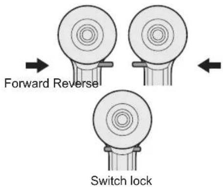
10) When storing or carrying the tool, set the Forward/Reverse lever to the center position (switch lock).
11) Do not strain the tool by holding the speed control trigger halfway (speed control mode) so that the motor stops.
12) Do not operate the speed selector switch (LOW-HIGH) while pulling on the speed control trigger. This can cause the rechargeable battery to wear quickly or damage the internal mechanism of the motor.

WARNING
- Do not use other than the Panasonic battery packs that are designed for use with this rechargeable tool.
- Panasonic is not responsible for any damage or accident caused by the use of recycled or counterfeit battery pack.
- Do not dispose of the battery pack in a fire, or expose it to excessive heat.
- Do not drive the likes of nails into the battery pack, subject it to shocks, dismantle it, or attempt to modify it.
- Do not allow metal objects to touch the battery pack terminals.
- Do not carry or store the battery pack in the same container as nails or similar metal objects.
- Do not charge the battery pack in a high-temperature location, such as next to a fire or in direct sunlight. Otherwise, the battery may overheat, catch fire, or explode.
- Never use other than the dedicated charger to charge the battery pack. Otherwise, the battery may leak, overheat, or explode.
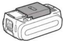
After removing the battery pack from the tool or the charger, always reattach the pack cover. Otherwise, the battery contacts could be shorted, leading to a risk of fire. - When the Battery Pack Has Deteriorated, Replace It with a New One. Continued use of a damaged battery pack may result in heat generation, ignition or battery rupture.
| Symbol Meaning | |
| V Volts | |
| --- | Direct current |
| nb | No load speed |
| ...min-1 | Revolutions or reciprocations per minutes |
| Ah | Electrical capacity of battery pack |
| To reduce the risk of injury, user must read and understand instruction manual. | |
| For indoor use only. | |
III. ASSEMBLY
Attaching or Removing Bit NOTE:
When attaching or removing a bit, disconnect battery pack from tool or place the switch in the center position (switch lock).
This tool is equipped with a keyless drill chuck.
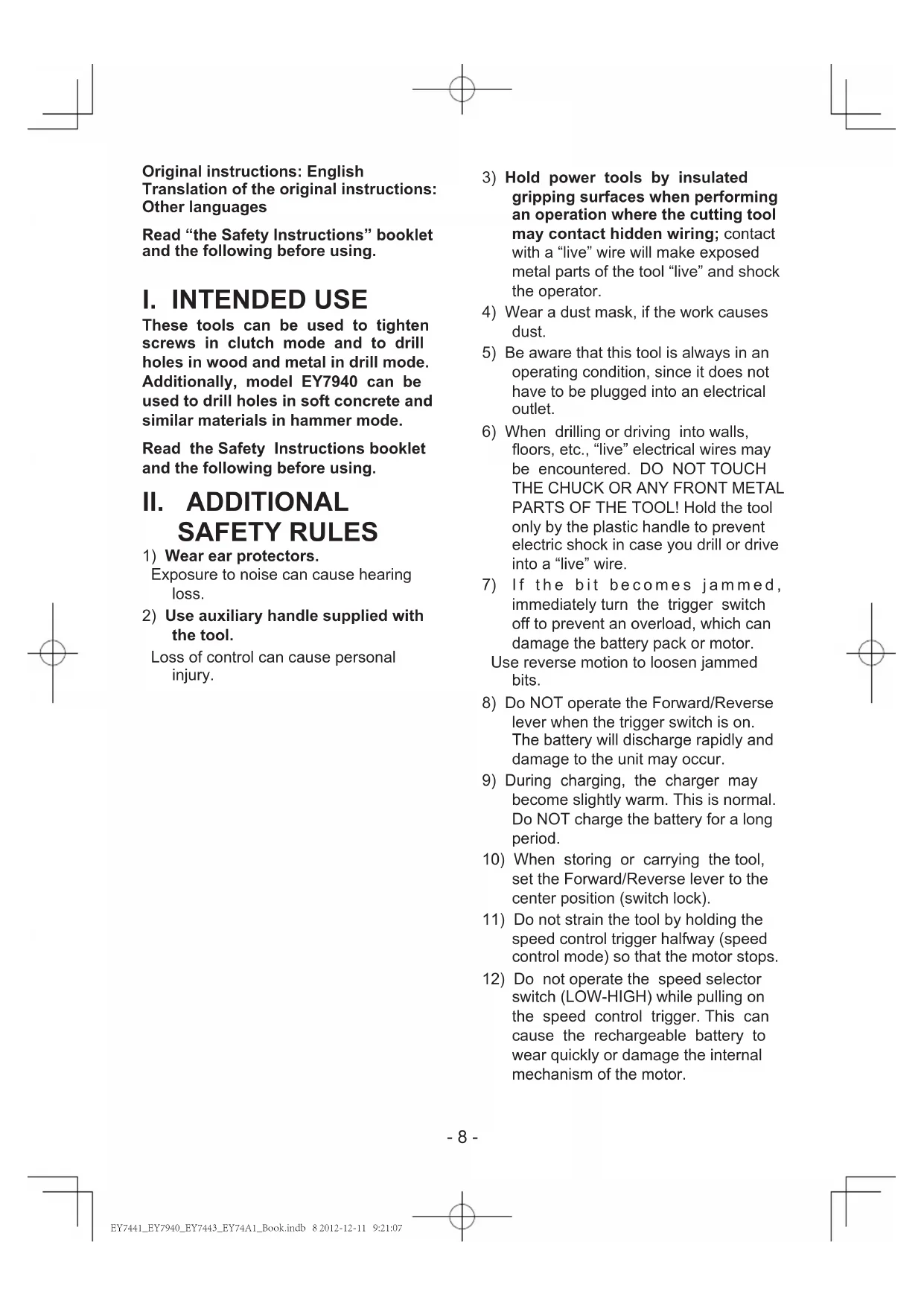
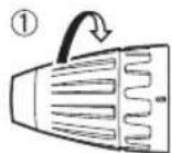
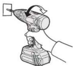
- Attachment
Insert the bit and turn the lock collar clockwise (looking from the front) to tighten firmly until it stops clicking.
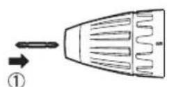
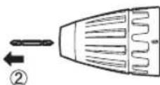
- Removal
Turn the lock collar counterclockwise (looking from the front), then remove the bit.
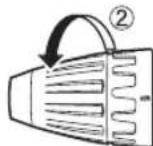
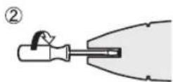
NOTE:
If excessive play occurs in the chuck, secure the drill in place and 1 open the chuck jaws by turning the lock collar and 2 tighten the screw (left-handed screw) with a screwdriver by turning it counterclockwise (viewed from the front).
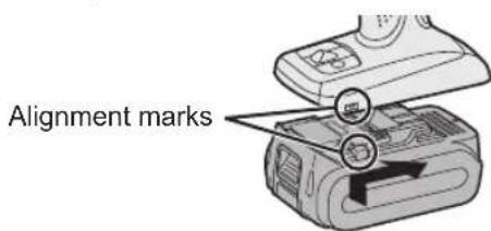
Attaching or Removing Battery Pack
- To connect the battery pack:
Line up the alignment marks and attach the battery pack.
- Slide the battery pack until it locks into position.
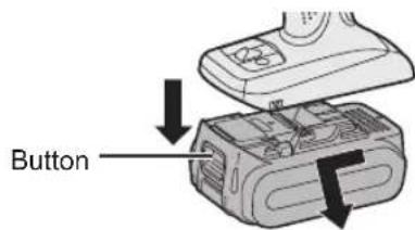
- To remove the battery pack:
Pull the button from the front to release the battery pack.
- The speed increases with the amount of depression of the trigger. When beginning work, depress the trigger slightly to start the rotation slowly.
- A feedback electronic controller is used to give a strong torque even in low speed.
- The brake operates when the trigger is released and the motor stops immediately.
NOTE:
When the brake operates, a braking sound may be heard. This is normal.
CAUTION:
When operating the tool by pulling the trigger, there may be a momentary lag before rotation starts. This does not signal a malfunction.
- This lag occurs as the tool's circuitry starts up when the trigger is pulled for the first time after installing a new battery pack or after the tool has not been used for at least 1 minute (or at least 5 minutes when the LED is on). Rotation will start without any lag during second and subsequent operations.
Switch and Forward/Reverse Lever Operation
CAUTION:
To prevent damage, do not operate Forward/Reverse lever until the bit comes to a complete stop.
Forward Rotation Switch Operation
- Push the lever for forward rotation.
- Depress the trigger switch slightly to start the tool slowly.
- The speed increases with the amount of depression of the trigger for efficient tightening of screws and drilling. The brake operates and the chuck stops immediately when the trigger is released.
- After use, set the lever to its center position (switch lock).
Reverse Rotation Switch Operation
- Push the lever for reverse rotation. Check the direction of rotation before use.
-
Depress the trigger switch slightly to start the tool slowly.
-
After use, set the lever to its center position (switch lock).
Clutch Torque Setting
Adjust the torque to one of the 18 clutch settings or "2" position (EY7441, EY74A1).
Adjust the torque to one of the 18 clutch settings or "2", "3" position (EY7940).
NOTE:
Always make sure to stop operation of the tool and disengage it from the work, when you select Hammering mode from Drilling mode or when you shift to Drilling mode from Hammering mode by rotating clutch handle.
CAUTION:
Set the clutch setting at this mark () before actual operation.

If the clutch handle cannot be set at "drilling" or "hammering" mode after driving with clutch function, set the clutch handle at position 1 and operate the clutch for a second.
Speed Selection
Choose a low or high speed to suit the use. (EY7441, EY7940, EY74A1)
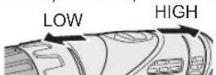
The more the variable speed control trigger is pulled, the higher the speed becomes.
Choose a low, high or auto speed to suite the use (EY7443)

LOW AUTOHIGH
The more the variable speed control trigger is pulled, the higher the speed becomes.
The EY7443 offers AUTO mode, which detects the load on the tool and automatically switches between HIGH and LOW speed operation.
When the load is low, the tool always starts operation in HIGH speed.
When the tightening torque increases, the tool switches to LOW speed. Keep a secure grip on the tool so that it doesn't twist out of your hands due to the increased torque.
When operating in AUTO mode, whether and when the tool switches between HIGH and LOW s p e d operation will depend on the specific work conditions. These variations in tool behavior are normal and do not represent a malfunction.
NOTE: When selecting AUTO on the EY7443
During AUTO mode operation, the tool may switch to LOW speed under light loads if there is little remaining battery life or if the battery pack temperature is low (0^ or less). In this case, charge the battery pack or place the battery pack in a warm location for at least one hour to allow it to warm up before use.
Depending on the load, the tool may switch back and forth between HIGH and LOW speed operation multiple times. If this switching is undesirable, set the tool to HIGH or LOW speed manually.
CAUTION:
-
Check the speed selector switch before use.
-
Use at low speed when high torque is needed during operation. (Using at high speed when high torque is required may cause a motor breakdown.)
-
Do not operate the speed selector switch (LOW-HIGH) while pulling on the speed control trigger. This can cause the rechargeable battery to wear quickly or damage the internal mechanism of the motor.
- See specifications for "MAXIMUM RECOMMENDED CAPACITIES".
CAUTION:
- To prevent excessive temperature increase of the tool surface, do not operate the tool continuously using two or more battery packs. The tool needs cool-off time before switching to another pack.
- Do not close up vent holes on the sides of the body during operation. Otherwise, the machine function is adversely affected to cause a failure.
- Do NOT strain the tool (motor). This may cause damage to the unit.
- Use the tool in such a way as to prevent the air from the body vent holes from blowing directly onto your skin. Otherwise, you may get burned.
Bit-locking Function
- With the trigger switch not engaged and a screwdriver bit locked in place, the tool can be used as a manual screwdriver (up to 22.6 N·m, 230 kgf·cm, 199 in·lbs).
There will be a little play in the chuck, but this is not a malfunction.
- This feature is handy for tightening screws that require more torque than the maximum torque of the driver (position 2 on the clutch), for confirming the tightness of a screw or to loosen an extremely tight screw.
How to Use the Belt Hook

WARNING!
- Be sure to attach the belt hook securely to the main unit with the screw firmly fastened. When the belt hook is not firmly attached to the main unit, the hook may disconnect and the main unit may fall.
This may result in an accident or injury.
Periodically check screw for tightness. If found to be loose, tighten firmly. - Be sure to attach the belt hook firmly and securely onto a waist belt or other belt. Pay attention that the unit does not slip off the belt. This may result in an accident or injury.
- When the main unit is held by the belt hook, avoid jumping or running with it. Doing so may cause the hook to slip and the main unit may fall.
This may result in an accident or injury.
- When the belt hook is not used, be sure to return it to the storing position. The belt hook may catch on something.
This may result in an accident or injury. - When the unit is hooked onto the waist belt by the belt hook, do not attach driver bits to the unit. A sharp edge object, such as a drill bit, may cause injury or an accident.
To Change the Belt Hook Location Side
The belt hook can be attached to either side of the unit.
- Removing the hook
(1) Remove the nut.
(2) Draw out the hook.
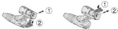
- Attaching the hook to the other side
(1) Insert the hook in the other side.
(2) Tighten the nut fully so that it securely fastened.
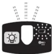
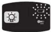
Control Panel
EY7441/EY7940/EY74A1
EY7443
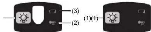
(1) LED light
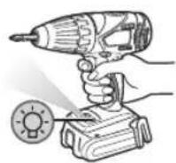
Before the use of LED light, always pull the power switch once.
Press the LED light button.
The light illuminates with very low current, and it does not adversely affect the performance of the tool during use or its battery capacity.
CAUTION:
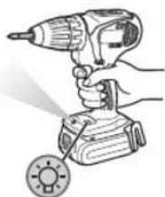
The built-in LED light is designed to illuminate the small work area temporarily.
- Do not use it as a substitute for a regular flashlight, since it does not have enough brightness.
- LED light turns off when the tool has not been used for 5 minutes.
Caution: DO NOT STARE INTO BEAM.
Use of controls or adjustments or performance of procedures other than those specified herein may result in hazardous radiation exposure.
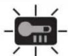
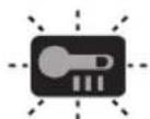
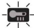
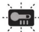
(2) Overheat warning lamp


Off
Illuminated:
Flashing:
(normal
Overheat
Overheat
operation)
(motor)
(battery)
Indicates operation has been halted due to motor or battery overheating.
To protect the motor or battery, be sure to note the following when carrying out this operation.
- If the motor or battery becomes hot, the protection function will be activated and the motor or battery will stop operating. The overheat warning lamp on the control panel illuminates or flashes when this feature is active.
- If the overheating protection feature activates, all ow the to o l to cool I thoroughly (at least 30 minutes). The tool is ready for use when the overheat warning lamp goes out.
- Avoid using the tool in a way that causes the overheating protection feature to activate repeatedly.
- If the tool is operated continuously under high-load conditions or if it is used in hot-temperature conditions (such as during summer), the overheating protection feature may activate frequently.
- If the tool is used in cold-temperature conditions (such as during winter) or if it is frequently stopped during use, the overheating protection feature may not activate.
- The ambient temperature range is between 0^ (32^) and 40^ (104^) . If the battery pack is used when the battery temperature is below 0^ (32^) , the tool may fail to function properly.
- When charging a cool battery pack (below 0^ (32^) ) in a warm place, leave the battery pack at the place and wait for more than one hour to warm up the battery to the level of the ambient temperature.
- If the tool is used in cold-temperature conditions (such as during winter) or if it is frequently stopped during use, the overheating protection feature may not activate.
The performance of the EY9L42 deteriorates significantly at and below 10^ due to work conditions and other factors.
(3) Battery low warning lamp

Off (normal operation)

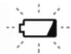
Flashing (No charge) Battery protection feature active
Excessive (complete) discharging of lithium ion batteries shortens their service life dramatically. The driver includes a battery protection feature designed to prevent excessive discharging of the battery pack.
- The battery protection feature activates immediately before the battery loses its charge, causing the battery low warning lamp to flash.
- If you notice the battery low warning lamp flashing, charge the battery pack immediately.
- If it is started with too little battery power remaining, the tool may stop operating without the battery low warning lamp flashing first. This indicates that there is too little battery power remaining to use the tool, and the battery pack should be charged before further use.
- If the tool is subject to a sudden load during use that causes the motor to lock up, the overdischarge prevention sensor may be triggered, and the battery low warning lamp may flash. The lamp will stop flashing once you address the cause of the motor's locking up and cycle the trigger.
EY7441/EY7940/EY74A1
EY7443
- The battery protection feature may activate when a high load is abruptly placed on the motor, even if ample battery charge remains. In this case, both the battery low warning lamp and LED light will flash (EY7443, EY74A1).
- If both the battery low warning lamp and LED light flash, reduce the force with which you are pushing on the driver or, if using a drill driver, adjust the speed switch to a lower setting (EY7443, EY74A1).
- If the tool does not switch between HIGH and LOW speed operation in AUTO mode, the motor will stop and the battery low warning lamp and the overheat warning lamp will alternately flash. It is not breakdown.
If both lamps alternately flash, depress the trigger again. (EY7443)
[Battery Pack]
For Appropriate Use of Battery Pack
Li-ion Battery Pack
- For optimum battery life, store the Li-ion battery pack following use without charging it.
- When charging the battery pack, confirm that the terminals on the battery charger are free of foreign substances such as dust and water etc. Clean the terminals before charging the battery pack if any foreign substances are found on the terminals.
- The life of the battery pack terminals may be affected by foreign substances such as dust and water etc. during operation.
-
When battery pack is not in use, keep it away from other metal objects like: paper clips, coins, keys, nails, screws, or other small metal objects that can make a connection from one terminal to another. Shorting the battery terminals together may cause sparks, burns or a fire.
-
When operating the battery pack, make sure the work place is well ventilated.
- When the battery pack is removed from the main body of the tool, replace the battery pack cover immediately in order to prevent dust or dirt from contaminating the battery terminals and causing a short circuit.
Battery Pack Life
The rechargeable batteries have a limited life. If the operation time becomes extremely short after recharging, replace the battery pack with a new one.
Battery Recycling
ATTENTION:
For environmental protection and recycling of materials, be sure that it is disposed of at an officially assigned location, if there is one in your country.
[Battery Charger]
Charging
CAUTION:
- If the temperature of the battery pack falls approximately below -10^ ( 14^ ), charging will automatically stop to prevent degradation of the battery.
- The ambient temperature range is between 0^ (32^) and 40^ (104^) . If the battery pack is used when the battery temperature is below 0^ (32^) , the tool may fail to function properly.
- When charging a cool battery pack (below 0^ (32^) ) in a warm place, leave the battery pack at the place and wait for more than one hour to warm up the battery to the level of the ambient temperature.
Cool down the charger when charging more than two battery packs consecutively. - Do not insert your fingers into contact hole, when holding charger or any other occasions.
To prevent the risk of fire or damage to the battery charger.
- Do not use power source from an engine generator.
- Do not cover vent holes on the charger and the battery pack.
- Unplug the charger when not in use.
NOTE:
Your battery pack is not fully charged at the time of purchase. Be sure to charge the battery before use.
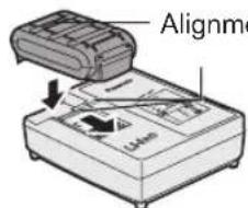
Battery charger
- Plug the charger into the AC outlet.
- Insert the battery pack firmly into the charger.
1) Line up the alignment marks and place the battery onto the dock on the charger.
2) Slide forward in the direction of the arrow.
-
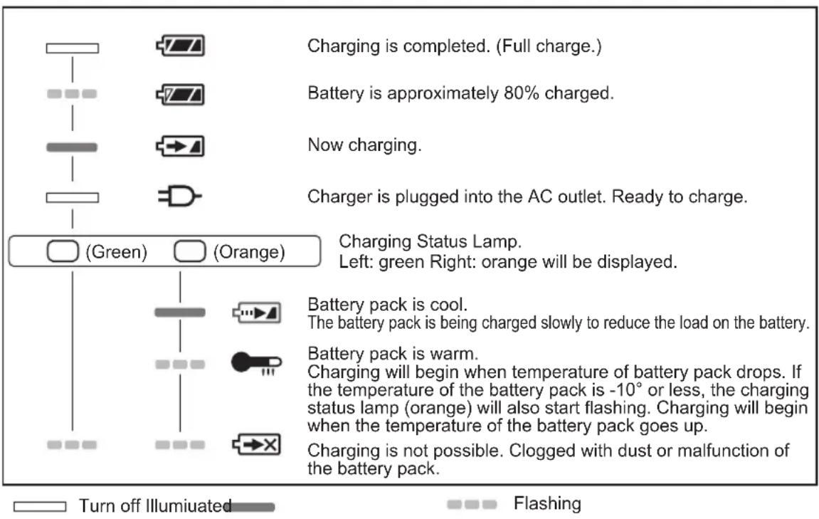
During charging, the charging lamp will be lit. When charging is completed, an internal electronic switch will automatically be triggered to prevent overcharging.
-
Charging will not start if the battery pack is warm (for example, immediately after heavy-duty operation).
The orange standby lamp will be flashing until the battery cools down. Charging will then begin automatically.
- The charge lamp (green) will flash slowly once the battery is approximately 80% charged.
-
When charging is completed, the charging lamp in green color will turn off.
-
If the temperature of the battery pack is 0^ or less, charging takes longer to fully charge the battery pack than the standard charging time.
Even when the battery is fully charged, it will have approximately 50% of the power of a fully charged battery at normal operating temperature. - Consult an authorized dealer if the charging lamp (green) does not turn off.
- If a fully charged battery pack is inserted into the charger again, the charging lamp lights up. After several minutes, the charging lamp in green color will turn off.
LAMP INDICATIONS
Information for Users on Collection and Disposal of Old Equipment and used Batteries

These symbols on the products, packaging, and/or accompanying documents mean that used electrical and electronic products and batteries should not be mixed with general household waste.
For proper treatment, recovery and recycling of old products and used batteries, please take them to applicable collection points, in accordance with your national legislation and the Directives 2002/96/EC and 2006/66/ EC.
By disposing of these products and batteries correctly, you will help to save valuable resources and prevent any potential negative effects on human health and the environment which could otherwise arise from inappropriate waste handling.
For more information about collection and recycling of old products and batteries, please contact your local municipality, your waste disposal service or the point of sale where you purchased the items.
Penalties may be applicable for incorrect disposal of this waste, in accordance with national legislation.
For business users in the European Union
If you wish to discard electrical and electronic equipment, please contact your dealer or supplier for further information.
[Information on Disposal in other Countries outside the European Union]
These symbols are only valid in the European Union. If you wish to discard these items, please contact your local authorities or dealer and ask for the correct method of disposal.
Note for the battery symbol (bottom two symbol examples):
This symbol might be used in combination with a chemical symbol. In this case it complies with the requirement set by the Directive for the chemical involved.
V. MAINTENANCE
Use only a dry,soft cloth for wiping the unit. Do not use a damp cloth, thinner, benzine, or other Volatile solvents for cleaning.
In the event that the inside of the tool or battery pack is exposed to water, drain and allow to dry as soon as possible. Carefully remove any dust or iron filings that collect inside the tool. If you experience any problems operating the tool, consult with a repair shop.
VI. ACCESSORIES
Use only bits suitable for size of drill's chuck.
VII. APPENDIX MAXIMUM RECOMMENDED CAPACITIES
| Model EY7441 EY7940 EY7443 EY74A1 | ||||
| Screw driving | Machine screw M5 | |||
| Wood screwø6.8 mm | ||||
| Drilling | Self-drilling screwø6 mm | |||
| For Woodø35 mm | ||||
| For Metalø13 mm | ||||
| For Masonry -ø13 | mm- | - | ||
VIII. SPECIFICATIONS
MAIN UNIT
| Model EY7441 EY7940 EY7443 EY74A1 | |||||||
| Motor voltage 14.4 V 14.4 V 18 V | |||||||
| No load speed | Low | 70~400 min-1 | 60~400min-1 | 50~480min-1 | |||
| High | 200~1400 min-1 | 160~1400min-1 | 130~1400min-1 | ||||
| AUTO-- | 160~1400min-1 | - | |||||
| Blows Rate Per Minute | Low-- | 1260~7200 min-1 | - - - | ||||
| High-- | 3600~25200 min-1 | - - - | |||||
| Chuck capacityø1.5 mm -ø13 mm | |||||||
| Clutch torque | Approx 0.5N m-4.4Nm | Approx 1.0N m-4.4Nm | Approx 0.5N m-4.4Nm | Approx 0.5N m-4.4Nm | |||
| Overall length 193 mm 200 mm 199 mm 203 mm | |||||||
| Weight (with battery pack EY9L44) | 1.75 kg 1.8 kg 1.85 kg 1.85 kg - | ||||||
| Weight (with battery pack EY9L45) | 1.75 kg 1.8 kg 1.85 kg 1.85 kg - | ||||||
| Weight (with battery pack EY9L50) | - - - - - - - - - - - - - - - - - - - - - - - - - - - - - - - - - - - - - - - - - - - - - - - - - - - - - - - - - - - - - - - - - - - - - - - - - - - - - - - - - - - - - - - - - - - - - - - - - - - - - | ||||||
| Weight (with battery pack EY9L51) | - - - - - - - - - - - - - - - - - - - - - - - - - - - - - - - - - - - - - - - - - - - - - - - - - - - - - - - - - - - - - - - - - - - - - - - - - - - - - - - - - - - - - - - - - - - - - - - - | ||||||
| Noise vibration | See the included sheet | ||||||
BATTERY PACK
| Model No. | EY9L41 | EY9L42 | EY9L44 | EY9L45 | EY9L50 | EY9L51 |
| Storage battery | Li-ion Battery | |||||
| Motor voltage | 14.4V DC(3.6V x 4 cells) | 14.4V DC(3.6V x 8 cells) | 18V DC(3.6V x 10 cells) | |||
BATTERY CHARGER
| Model No. | EY0L81 | |||||
| Electrical rating | See the rating plate on the bottom of the charger | |||||
| Weight | 0.93 kg | |||||
| Charging time | EY9L41 | EY9L42 | EY9L44 | EY9L45 | EY9L50 | EY9L51 |
| Usable:45min | Usable:30min | Usable:50min | Usable:65min | Usable:50min | Usable:65min | |
| Full:60min | Full:35min | Full:65min | Full:80min | Full:65min | Full:80min | |
| Model No. | EY0L82 | |||||
| Electrical rating | See the rating plate on the bottom of the charger | |||||
| Weight | 0.93 kg | |||||
| Charging time | EY9L41 | EY9L42 | EY9L44 | EY9L45 | EY9L50 | EY9L51 |
| Usable:35min | Usable:30min | Usable:40min | Usable:50min | Usable:40min | Usable:55min | |
| Full:50min | Full:35min | Full:55min | Full:60min | Full:55min | Full:70min | |
NOTE: This chart may include models that are not available in your area.
Please refer to the latest general catalogue.
NOTE: For the dealer name and address, please see the included warranty card.
ONLY FOR U.K.
IX. ELECTRICAL PLUG INFORMATION
FOR YOUR SAFETY PLEASE READ THE FOLLOWING TEXT CAREFULLY
This appliance is supplied with a moulded three pin mains plug for your safety and convenience.
A 5 amp fuse is fitted in this plug.
Should the fuse need to be replaced please ensure that the replacement fuse has a rating of 5 amp and that it is approved by ASTA or BSI to BS1362.
Check for the ASTA mark or the BSI mark on the body of the fuse.
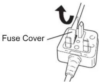
If the plug contains a removable fuse cover you must ensure that it is refitted when the fuse is replaced.
If you lose the fuse cover the plug must not be used until a replacement cover is obtained.
A replacement fuse cover can be purchased from your local Panasonic Dealer.
IF THE FITTED MOULDED PLUG IS UNSUITABLE FOR THE SOCKET OUTLET IN YOUR HOME THEN THE FUSE SHOULD BE REMOVED AND THE PLUG CUT OFF AND DISPOSED OF SAFELY. THERE IS A DANGER OF SEVERE ELECTRICAL SHOCK IF THE CUT OFF PLUG IS INSERTED INTO ANY 13 AMP SOCKET.
If a new plug is to be fitted please observe the wiring code as shown below.
If in any doubt please consult a qualified electrician.
IMPORTANT:
The wires in this mains lead are coloured in accordance with the following code:
Blue: Neutral
Brown: Live
As the colours of the wire in the mains lead of this appliance may not correspond with the coloured markings identifying the terminals in your plug, proceed as follows.
The wire which is coloured BLUE must be connected to the terminal in the plug which is marked with the letter N or coloured BLACK.
The wire which is coloured BROWN must be connected to the terminal in the plug which is marked with the letter L or coloured RED.
Under no circumstances should either of these wires be connected to the earth terminal of the three pin plug, marked with the letter E or the Earth Symbol 1一
How to replace the fuse: Open the fuse compartment with a screwdriver and replace the fuse and fuse cover if it is removable.
This apparatus was produced to BS800.
Clignotant: Surchauffe (battery)
Lyser: Overhettning (motor)
Blinkande: Overhettning (batteri)
(2) Varsellampe for overoppheting


Av (normalt arbeid)
Lyser:
Blinker:
Overopbehing (motor)
VIII. TEKNISET TIEDOT
PÄALAITE
Panasonic Testing Center
Winsbergring 15,
22525 Hamburg,
Germany
Panasonic Corporation 1006,Kadoma,Osaka 571-8501,Japan http://panasonic.net
EN. GR. FR. IT. ND. ES. DN. SW. NR. FN
EY972074412 2012 12 Printed in China