
T754 - Tumble drier ASKO - Free user manual and instructions
Find the device manual for free T754 ASKO in PDF.
| Product Type | Vented Dryer |
| Brand | ASKO |
| Model | T754 |
| Loading Type | Front-loading |
| Drying Capacity | 7 kg |
| Installation | Freestanding or stackable on ASKO washing machine |
| Air Venting | Hose supplied, 3 positions (rear, right, left) |
| Heating Power | Switchable 1950 W (10 A) or 2500 W (16 A) |
| Power Supply | 230 V, 50 Hz (estimated) |
| Dimensions (H x W x D) | 850 x 595 x 590 mm (estimated) |
| Net Weight | 45 kg (estimated) |
| Programs | Multiple with selector (temperature, anti-crease, quick, etc.) |
| Display | Screen with clock (12h, 24h or remaining time mode) |
| Available Languages | French, English, Swedish, Danish, Norwegian, Finnish, German, Italian, Spanish, Russian, Dutch |
| Noise Level | Not specified |
| Maintenance | Clean lint filter after each cycle |
| Safety | Type A residual current circuit breaker, grounded plug |
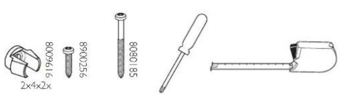
| Supplied Accessories | Ventilation hose, fittings, cups, and brackets for stacking |
| Maximum ventilation hose length | 8 m (inner diameter 102 mm) |
Frequently Asked Questions - T754 ASKO
User questions about T754 ASKO
0 question about this device. Answer the ones you know or ask your own.
Ask a new question about this device
Download the instructions for your Tumble drier in PDF format for free! Find your manual T754 - ASKO and take your electronic device back in hand. On this page are published all the documents necessary for the use of your device. T754 by ASKO.
USER MANUAL T754 ASKO
GB Installation instructions for vented tumble dryer
DA Installationsvejledning til aftrakstorretumblere
DE Installationsanleitung für den Abluftwäschetrockner
es Instrucciones de instalacion de la secadora con evacuation
FR Instructions d'installation du seche-linge à évacuation
No Installasjonsanvising for utluftingstørketrommel
NL Installatie-instructies voor de droogtrommel met luchtafvoer
PT Instruções de instalação paraária de secar roupa ventilada
RU Yka3aHnI NO yCTaHOBKe BEHTNAnpyeMoN CyuINbHOJ MaINHbI
Hormillitantäisen kuivausrummun asennusohje
SE Installationsanvisning for avluft torktumlare
sL Navodila za vgradnjo odzračevalnega susilinea stroja
Dansk 4
Deutsch 9
English 14
Espanol 19
Francais 24
Norsk 29
Nederlands 34
Portugese 39
Pycckn 44
Suomi 49
Svenska 54
Slovenian 59
EN We reserve the right to make changes.
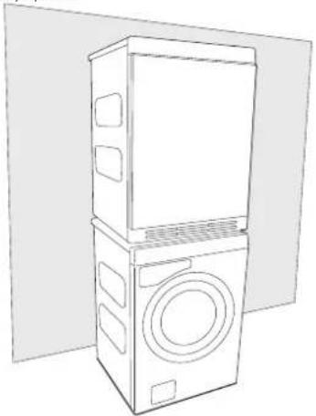
Fully built-in machine
The tumble dryer can be free-standing or in a stack. Remember that the tumble dryer produces heat and should therefore not be located in a room that is too small. If the room is very small, drying will take longer due to the limited quantity of air.
Caution!
- Any electrical installation must be carried out by qualified professionals.
- The machine must not be installed behind a lockable door, a sliding door or a door with hinges on the opposite side to those of the tumble dryer.
- The tumble dryer's plinth ventilation must not be blocked by a rug or the like.
Tip!
To improve ventilation, leave the door to the room where the tumble dryer is located open.
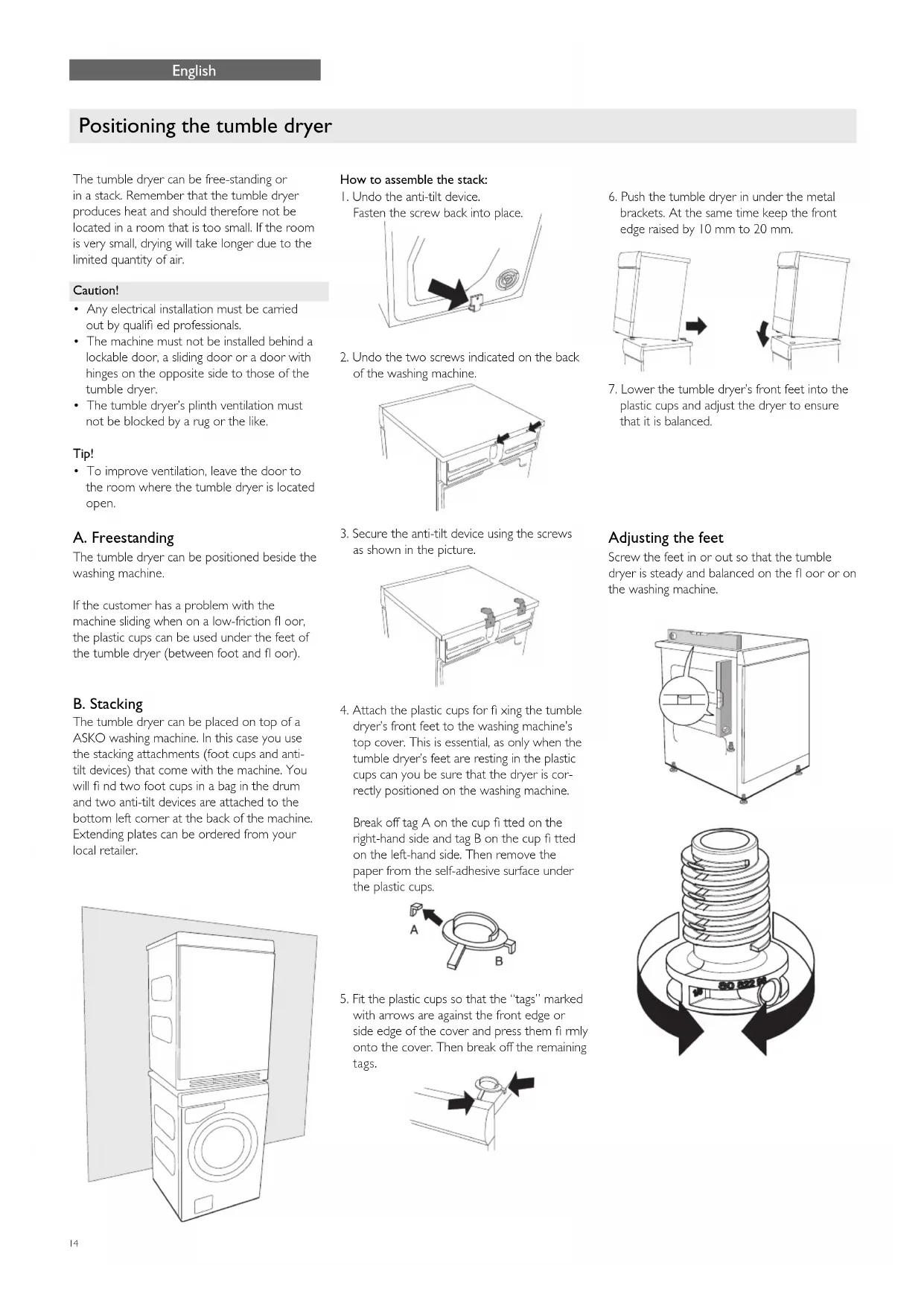
A. Freestanding
The tumble dryer can be positioned beside the washing machine.
If the customer has a problem with the machine sliding when on a low-friction floor, the plastic cups can be used under the feet of the tumble dryer (between foot and floor).
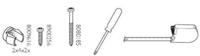
B. Stacking
The tumble dryer can be placed on top of a ASKO washing machine. In this case you use the stacking attachments (foot cups and anti-tilt devices) that come with the machine. You will find two foot cups in a bag in the drum and two anti-tilt devices are attached to the bottom left corner at the back of the machine. Extending plates can be ordered from your local retailer.
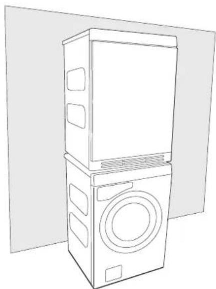
How to assemble the stack:
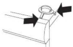
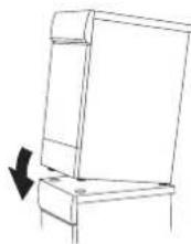
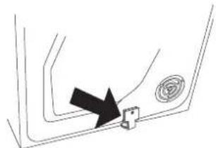
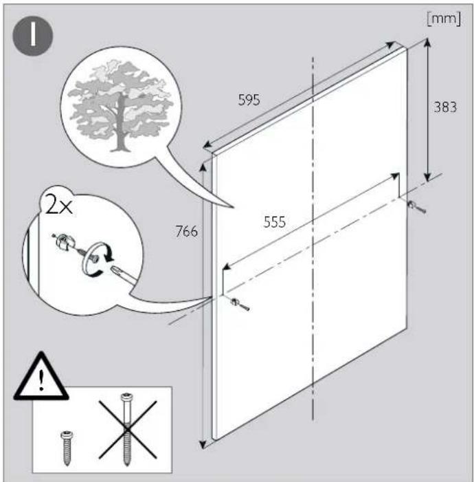
I. Undo the anti-tilt device.
Fasten the screw back into place.
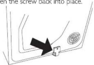
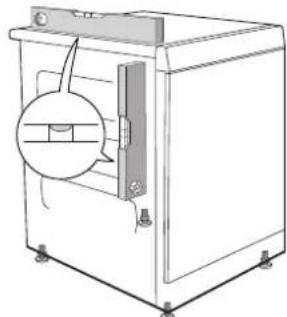
- Undo the two screws indicated on the back of the washing machine.
- Secure the anti-tilt device using the screws as shown in the picture.
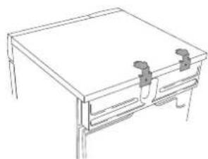
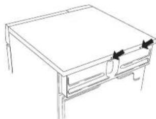
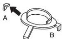
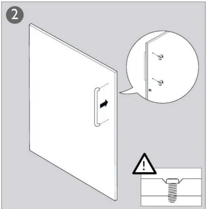
- Attach the plastic cups for fixing the tumble dryer's front feet to the washing machine's top cover. This is essential, as only when the tumble dryer's feet are resting in the plastic cups can you be sure that the dryer is correctly positioned on the washing machine.
Break off tag A on the cup fitted on the right-hand side and tag B on the cup fitted on the left-hand side. Then remove the paper from the self-adhesive surface under the plastic cups.
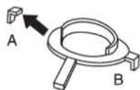
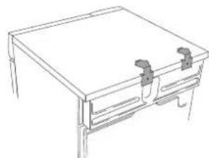
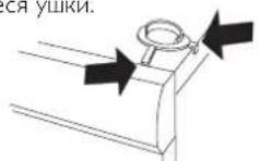
- Fit the plastic cups so that the "tags" marked with arrows are against the front edge or side edge of the cover and press them firmly onto the cover. Then break off the remaining tags.
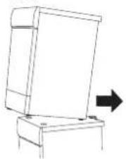
- Push the tumble dryer in under the metal brackets. At the same time keep the front edge raised by 10 mm to 20 mm.
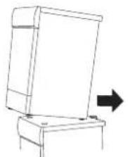
- Lower the tumble dryer's front feet into the plastic cups and adjust the dryer to ensure that it is balanced.
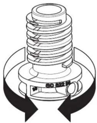
Adjusting the feet
Screw the feet in or out so that the tumble dryer is steady and balanced on the floor or on the washing machine.

Air evacuation
Waste air from the tumble dryer must be taken to an evacuation duct or to an outlet in the wall using the vent hose supplied.
Connection to the tumble dryer
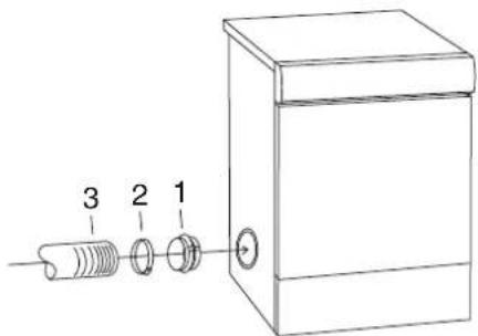
The tumble dryer has three options for venting air: at the back, on the right side and on the left side. One hole is open when the tumble dryer is supplied. The other two have covers. The tumble dryer comes with a connector (1), a plastic band (2) and a vent hose (3).
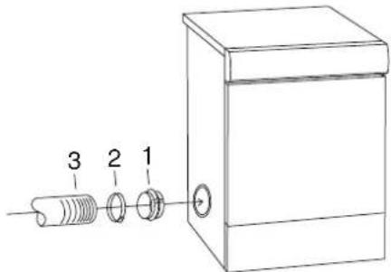
Fit the air evacuation system as follows:
- Slip the vent hose onto the connector and secure it using the plastic band.
- Remove the plastic cover if you want to fit the vent hose to one of the holes other than the one already open.
- Insert the connector with the vent hose into the opening.
- Place the cover over the open hole.
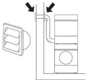
Connection to the evacuation duct
The vent hose must take the shortest and straightest route possible from the tumble dryer to the evacuation duct. Trim or cut the vent hose if it is too long. If necessary, the vent hose can be extended to a maximum of 8 metres (inner diameter 102mm ). If a longer hose is needed, a larger inner diameter is required in order to maintain the tumble dryer's fan capacity. Any bends must be as gradual as possible. If 90^ bends are necessary, there must be no more than four. More bends will reduce the tumble dryer's fan capacity.
Caution!
Air from the tumble dryer must not be fed through ducts used for equipment that burns gas or other fuels.
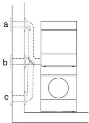
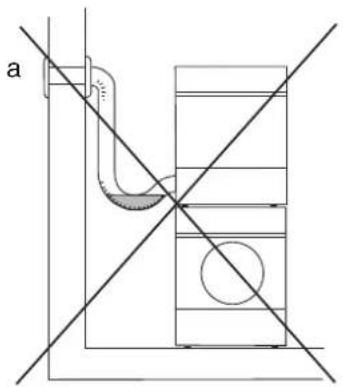
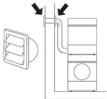
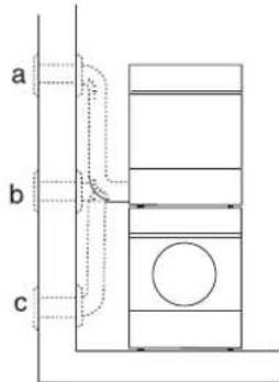
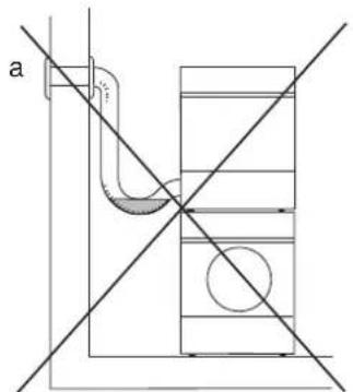
Installation in a hot environment
If you install the tumble dryer in a small room with a high atmospheric humidity, where the temperature may exceed 25^ , there is a risk of condensation accumulating in a kink and obstructing the air flow, resulting in poor drying results. To avoid this happening, the hose must not be fitted so that it goes up (a), but instead so that it is horizontal (b) or goes down (c) from the drier.
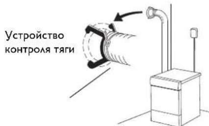
Accessories
If the vent hose runs to an outlet in the wall, you can prevent the inflow of cold air by fitting a ventilation grill. This grill can be installed either outside or inside.
If there is only one evacuation duct from the room, a "draught check" must be fitted.
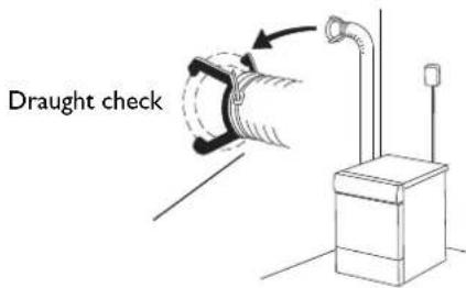
These accessories can be purchased from your retailer.
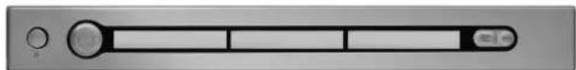
Start instructions


Start instructions
You will be prompted to select the display language when you have connected your machine and start it for the first time.
- Turn the programme selector and choose the required language.
- Press Start to save the selection and return to the programme menu.
Start instructions
The first time the machine is connected to a power supply, you need to select the language for the machine's menus and set the clock. If the power is cut before this is completed, the process must be restarted.
Note:
All selections must be made.
Select language
If you want to use the default language, press the Start button to confirm. Otherwise, use the up and down arrow buttons to select: AU English, US English, svenska,ISK, suomea,
Francais, Deutsch, Italiano, espanol, Pycckn, nederlands.
Press the Start button to confirm.
Set the clock to 12h, 24h, or remaining program time display
The clock is displayed in the middle of the display. Use the up and down arrow buttons to choose 12h, 24h, or remaining program time display. Press the Start button to confirm. If you select 12h or 24h, the clock setting menu automatically opens.
Set the clock
Press the up arrow button until the correct hour is displayed. Press the program selector (the big arrow) to save. Press the down arrow button until the correct minutes are displayed. Press the Start button to confirm.
Electrical installation
The electrical wall socket must be placed outside of the installation area to be easily accessible.
The machine must only be connected to an earthed wall socket.
Any residual current devices must be type A.
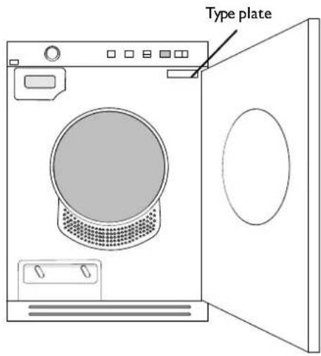
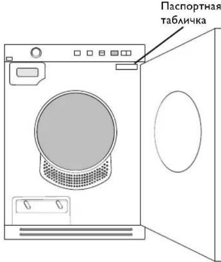
Connection on delivery
Information about the electrical connection can be found on the type plate. Compare the data with the mains supply data.
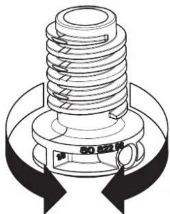
Switch-over
It is possible to switch between 10A (heat output 1950W) and 16A (heat output 3000W). The switchover must be performed by a qualified electrician. Below we describe how to do this for each model.
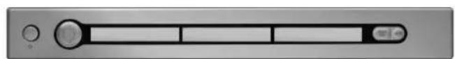
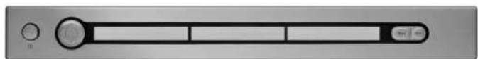
LINE SERIES™-CLASSIC

- Turn off the machine using the main power switch.
- Press and hold the "Temperature button" 8^ and then switch on the Main power switch.
- If the upper right LED by the programme selector and the LED by the "Temperature" button are lit then the machine is set for 10A and 1950W. If both the upper and lower right LEDs by the programme selector and the LED by the "Temperature" button are lit then the machine is set for 16A and 3000W. Press the "Anti crease" button once to switch the heat output.
- Press the Stop button to save.

- Turn off the machine using the main power switch.
- Press and hold the "Anti crease button" ^2h and then switch on the Main power switch.
- If the upper right LED by the programme selector and the LED by the "Anti crease" button are lit then the machine is set for 10A and 1950W. If both the upper and lower right LEDs by the programme selector and the LED by the "Anti crease" button are lit then the machine is set for 16A and 3000W. Press the "Time saver" button once to switch the heat output.
- Press the Stop button to save.
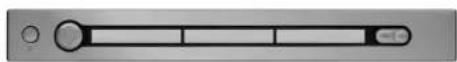
LINE SERIES™-STYLE
Fully built-in machine
I. Turn off the machine using the main power switch.
2. Press the Stop button and switch on the machine with the Main power switch. Then press the Stop button 5 times within 10 seconds.
3. Press the up or down arrow button and choose between "Heater 2 On" (3000W/16A) and "Heater 2 Off" (1950W/10A).
4. Press the Start button once to save your selection. The machine returns to the programme menu.

Standard machine
I. Turn off the machine using the main power switch.
2. Press the Stop button and switch on the machine with the Main power switch. Then press the Stop button 5 times within 10 seconds.
3. Turn the programme selector and choose between "Heater 2 On" (3000W/16A) and "Heater 2 Off" (1950W/10A).
4. Press the Start button once to save your selection. The machine returns to the programme menu.
LINE SERIES™-LOGIC

I. Turn off the machine using the main power switch.
2. Press and hold the "Temperature button" and then switch on the Main power switch.
3. Turn the programme selector and choose between "Heater 2 On" (3000W/16A) and "Heater 2 Off" (1950W/10A).
4. Press the Start button once to save your selection. The machine returns to the programme menu.
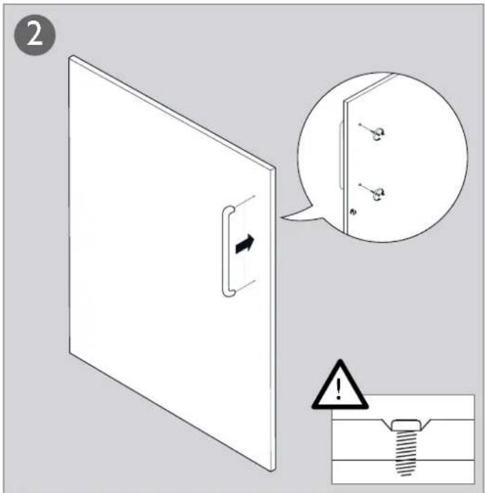
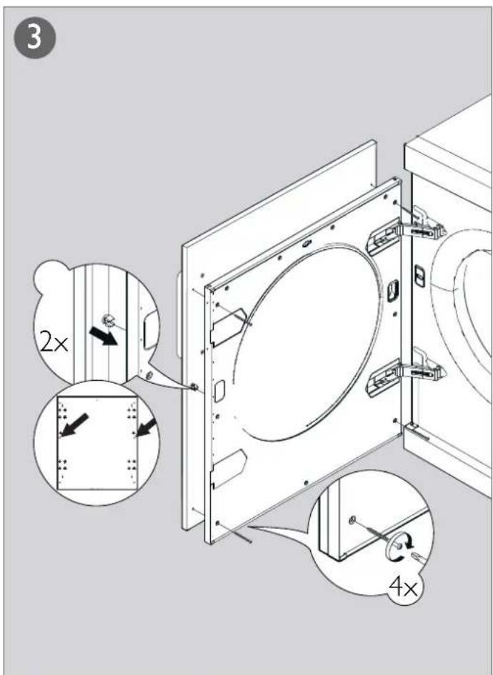
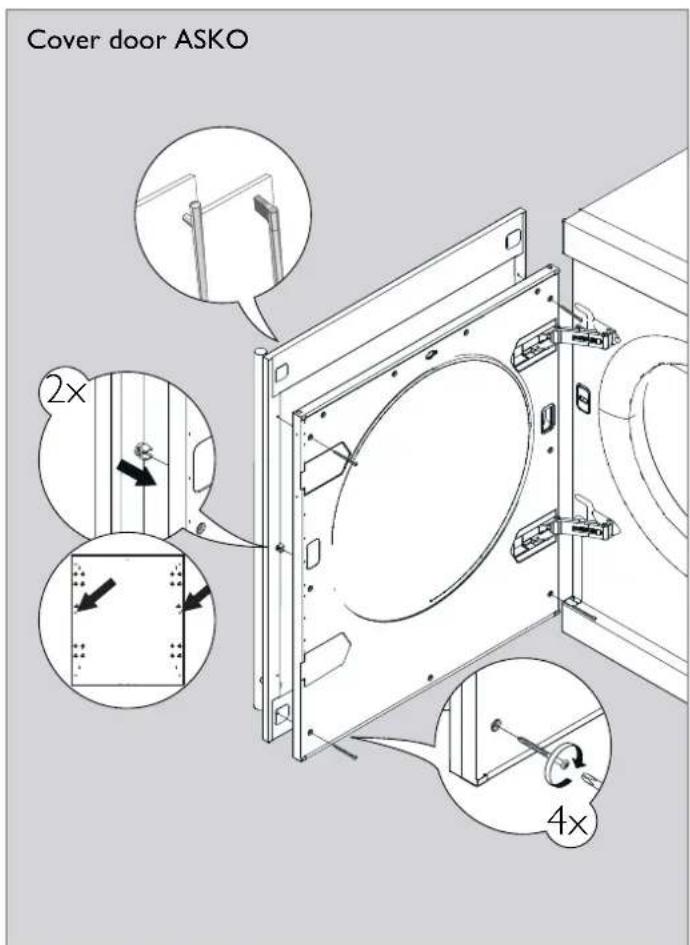
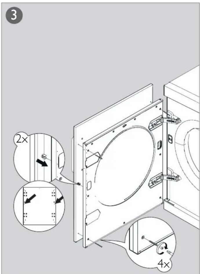
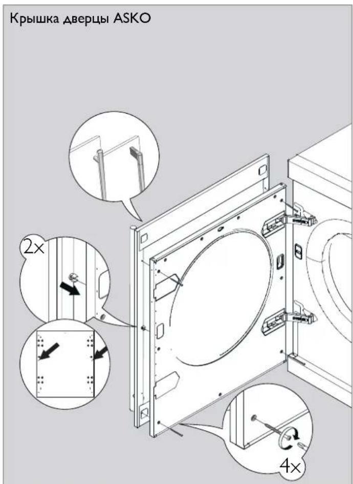
Fitting the cover door
Note!
The instructions for fitting the cover door only apply to the illustrated model.

B. YcTaHOBKa Ha CTnpaAaHoH MaWuHHe
CyuMbHb6apabAHMOKHO NOMeCTNb
Ha CTnpaBHyO MaunHy ASKO.B 3TOM
Cayae CcAeyETNIOAb3OBaTB MOHTaXHBie
KpeAENH (KOAnaKn DAA HOKe K
IPOTNBOONPOKNDbBAIOUne YCTPOINCTBa),
BXoAUNIE B KOMNAEKT NOCTABKN MaunHBi.
B NaKeTe BHyTpN6apabaha HxOaTcR DA
koAaNka, a DBA IPOTNBOONPOKNDbBAIOUHX
yCTPOINCTBa INPKPeINAEHb B HIXHEM AEBOM
yAY K 3aHei CTHeKMaunHBi. BblBNXHbIe
naHEM MOKHO 3aKa3aTb y NoCTaBUnkA
akCECCyApOB.
Kak yctahOBnTB cyuMbHyo MaunHy NOBepx CTnpaABHO MauHHbI:
1.Pa36epnteΦKcnpyiooee yCTpoiCTBO. BBepnTe BNHT o6paTHO.
2.OTnyCTnTe DBA BnHTa, NOKa3aHHbIX Ha 3aHcN CTeHKe CTnpaBHO MaunHbI.
3.3aKpeHnTe pKcnpyIOueyCTpOcTBO C NOMObBO BnHTOB, KaK NOKa3aHO Ha PnCyHKe.
4.3akpenTe NaactMacCOBie KOAnauKIN A KpeHnHnIepeDnHX HOKe cyuNbHO MaunHbK BepxHe KpUWe CTnpaBHm MaunHb. 2TO Heo6xoAMo, TAK Ka, NOMecTNB HOKKn CyuNbHOm MaunHb B IAACTMaCCOBBe KOAnauKn, Bbl ObecneHInTe ee PpaBnAbHOe NoAOXeHHe Ha CTnpaBHOn MaunHe.
OTAMNTe yIko A OT KOAnaKa,
yCTaHaBnBaEMO cnpaba, n yIko B
OT KOAnaKa, yCTaHaBnBaEMO cAeBa,
3aTeM ydaNTE 6ymary C CAMOKAEoWeCn
NOBepxHOCTn NOA NAACTMaCCOBbIMN
KOAnaKAMH.
5.YCTAHOBHTe NAACTMACCOBIE KOANAChK TaK, YTO6bI"yUKN",NOMEHHeHBe CTpeAKAMn HAXOANCb Ha IpeaHEm HA6OKOBOM KpaIO KpbuIKN, IN KpeNKo npHKMTe INK Kpblke. Iocae 3TOrO OTaOMtE OCTABWNEcA yUKN.
6.3aBnHbTe cyuMbHyIO MaunHy NOA MeTaAMHeCKNe CkO6bl. Pnp 3TOM NOAdepKINBAIte NepeADHOIO CTOPOH IpHNOAHrTo HA BICOT O10 mm 20 mm.

- OnyctTne nepaHne HOKc cyuabHO MaHHb B NactMaCCOBHe KOAnayn OtperynpyTe ee noaoKeHne, Yo6bl OHa CTOrAa POBHO.
PeryaPobKa HOxEK
3aBnHnBa Nn BbBnHnBa HOxKn, OTepyAmpyTe IN BbcOTy TaK, YTO6bl CyuHaMaunHa PoBHO uYCTOuHBO CTOnA Ha NoAUY HA CTnpAabHO MaunHe.
OTBOA BO3Ayx
Otpa6oTaHHbI Bo3ayx OT CyuHbHO
MaHnHbIOAXEH OTBOAHtBcR B
BEHTNAUHOHHbIKaHaANOTBepCTHe
BCTeHe PnI NOMOIN NOCTaBAReMOrO
BEHTNAUHOHHORU HAHA
POnCoeAnHeHneK cyuHaBHO MaunHe
PpeAcmOTpeHb TPNBapnHaTc OTBOda
BO3yxa IPOADyBN 3 cyuMbHO MaunHBi
C3aH, CnpBaN caeBa. HenocpeActBeHo
IOCAe IOCTABKn OHO N3 OTBepCTNI
OTKpbITo. OCTaHbIe DBA 3kPbITbI
KpblkAMn.CyuaHBaMaUNHaIOCTaBAETcR
B KOMnAEKeT C COeAHINHTeAm (1),
IIAACTMaCCOBbIM IOrCKOM (2) N OTBOAhIM
UAAHROM (3).
IooTOOBbTe CnCTemy OTBOa BO3aXcAeDyUOuM O6pa3OM:
I. HaaBnHbTe OTOBHOH WAAHr HA COeAHNHTeAb N 3aKpENTe ERO PAACTMACCOBBIM XOMYTOM
2.EaH BxOTnTe PncoeAHHTb OTBOHOI 0AAH K OADHomY H3 aKpblTxO TBepCTN, CHMMTE C 3TOFO OTBepCTN IAACTMaCCOByKOblkY.
3.BCTaBBTe BOTBepCTHe COeAMHHTeAB C npKpePAEHbIM K Hemy IHaAHROM.
4.3aKpoTe KpbIikOu OTkpBIOe OTBepCTne.
NoCoeAnHeHne KOTBOHOmy KaHaA
OTBOHOH ⅢAHR DOXKEN 6bITb NO
BO3MOXHOCTN IPOAOXEN IO CAMOMY
KOPOTKOMY IN PPMOMY IYTN OT CYUNABHOH
MAUINHb DO OTBOHOHO KaHAA. ECn OTBOHOH
ⅢAHR CAMUKOM DAHHB, NODROHTE HN
O6peXbTe erO. B CAYae HEoBXoAMOCTH
OTBOHOH ⅢAHR MOXHO YDAHNHTb MAXCIMYM
DO 8 MetPOB (npn BHTpeHHem DAmEeTpe 102 MM). ECn Tpe6yeTcB OoAE DAHHB II AHAH, TO DA NOAepKaHn IPOANBDOANTeBAHOCTN
BEHTNArTOPA CyUNABHO MauINHb Tpe6yeTcB
BOAHB HHTpeHHN DAmEeTp IAAHa. BCE
I3RbI BOAKHb 6bITb KAK MOXHO 6oAee
IIaABHIM. ECn HeoBXoAMMb I3RbI POA
YTAOM 90^ , IX DOXHO 6bITb HE 6oAbe
YeTbIpex. YBeaunHeHne KOAnueCTBa I3RbOB
PnIBoAHT K CHIKHEHIO POn3BOAHTeBAHOCTN
BEHTNArTOPA CyUNABHO MaUNHB.
BHHMaHHe!
Bo3aYxN3 cyuHbON MaunHbI Heab3r OTBOaNTb NO KaHaAM,NCIOAByeMbIM AAB 60bOpyObaHnB, B KOTOpOM IPOUN3BOaNTc CkInraHne r3a nn APyrOToTOnANBa.
YcTaHOBka B NOMEeHNN C NOBbIeHHoTEmnepaTypoi
PnYcTaHbKe cyuMbHO MaunHbB MaOM NOMEUeHN C BicOKoB BAaXHOCTbO BO3yxa, TEMepaTypaB KOtOpM MoKet npBeBuaTb 25 ^ C, BO3NkaeOTaCHOCb KOHaehCaUN BOaB, KOTopA cKaANBaETcB MecTx NapErna, NepeKpbBaI pNTOK BO3yxa, YTO pNBOaNT K yxyuHeHIO kauEcTBa cyuKn.Bo u36ekaHne TaKoI CHTyaLIM, UAAHr He CaeDyET NOABoANTb TaKIM O6pa30M, YTO6bOH UIe BEpTNkAbHo BBepx (a), HO HAObOpT, YTO6bl OH OTXoHn TropNoHTaHbHO (b) MM BEpTNkAbHO BHIN (c) OT CyuNbHO MaunHbI.
PnHaAeXHOCTH
ECANOTBOADHOIAAHBEaETK BbIyckHOMY OTBepCTNIO BCTHe,MOXHO IpeoTBPaNTb NOACOC XOAODHOROB3yxa,yCTaHOBB BEHTNAUHOHHyo peWetky.Takyo peWetky MOXHO YCTaHOBNt KaK Chapyk, TaK Nn3Hytpn.
ECANB NOMEHIN IMeETC TAObKO OADNHOBOHOH KaHa, HcO6XoAMO YCTaHOBTb "yCTPOIcTBO KOHTPOA TARN".
3TN pInHaAeXHoCTN MOxHO pIno6peCTN B MecTHOH PO3HNHO cETH.
HctpyKunn no 3ayncky


Hnctpykun no 3anycky
Iocae IIOKMOHEnnepBOrO nYcKa CTnpAahOBMaIIHHb6yAEt OTo6paKeHo nprrAaHeHBeBbPaTb 3bIK OTo6paKeHn.
I. NOBOPaHbAte IpeEKAIOHaTeAB npOrpaMM ABA BbIbopa Tpe6yEmo r3bka.
2.HaKMnTe《Iyck/OctaHOBkaAa coXpaHHe Hn Bb6opa n BO3BpTa B MeHo IpOrpaMMbl.

Hnctpykun no zanycky
PnNepBOM NOAIOHHeHH MaUNHBK NCTOHNYIHTAHNEO6XoAMMO Bb6paTb Ra6IK AARNCNOAB3OBAHNA B MEHO MAUHNb, a TaKKeYCTAHOBNTb Yacbl. ECan B 3TO Bpemr IODaHaNITAHIN PpePBETc, npoecC Heo6xOAMo 6ydetHauatcb Chauaaa.
PnIMeHaHHe:
CaeayetBbIpaTb BCE HeoXoAVMbe npaMeTpbl.
Bb6op a3bika
ECAN Bbl XOTHTe NCOA3OBA Tb 3bIK,
yCTaHOBAAHBBI IO yMOAHAHIO, HAKMTTe
AAn NOATBepKdEHNr KONKy (YcK).B
IPOTNBOM CAYHae NCOA3yTE KONKN Co
CTpeAKAMN BBEPX N BHIN3 AABbBOpa Ra3bika:
AU English, US English,svenska,dansk,norsk,
suomea, Francais,Deutsch, Italiano,ESPNOL,
Pycckn, nederlands.
HakMTte AAn NOATBepKdEHNr KONKy "TcK".
YcTaHOBka 12- HAN 24-HacOBOro peXnMa YacOB AN6O OTO6paXeHne BpeMeHN, OCTaBWeOra DO KOHa pPpAMMbI.
HacbI OTo6paKaIOCTB CpeAINHe 3KpaHa.
NcnoAbyte KHOIN Co CTpeAAM BBepx Hn3, Yo6bbl6paTb 12-, 24-ACOBoB peKIM
AACOB Nn OT6paNTb OCTaBWeecr Bpem.
HaKMITE AAn NOATBePKeHn KHOINy "Tyck". ECAN B6paTb 12- nN 24-ACOBoB peKIM, ABtOMaTIneCKn OTKpoeTc MeHIO
HAcTPOIN YAcOB.
YCTaHOBka YacOB
HaKIMaTe KHOHky CO CTpeAkoB Bepx DO OTo6paXeHnTpe6yEmo3HaehnHaCob. 4To6bl CoXPanHTb HaCTpoKy, HAKMITE nepeKaIOateAeIb npOrpamM (6oAbyIO CTpeKy).HaKIMaTe KHOHky CO CTpeAkoB BBepx AO OTo6paXeHnTpe6yEmo3HaueHnMIHyT.HAKMITE DAJ IOATBePckdEHHKHOHky"Pyck".
3AektpomOHTaX
HaTeHHa 3AekTpmecka po3eKa DOxHHa HAXoNTbC3a PpeEaMIMOHbI yCTaHOBKnTO6bIK He MoKHO bIAO AetKO O6paTbcN.
- ANyCKaETcIIOKIAOHeHMeMaUNHbI NCKAIOHTeABHO K 3a3eMaEHHO CTEHHO PO3eTke.
VCTPOCTBO3aUNTHOROOTKAOUCHENADoAKHO6bTbTnA.
IoAIOUeHHe IOCAe IOCTaBKn
HhOpMaunO6AeKTPnuecknxNoKaIOUeHNHXIINBOADNTCBNaCnOPTHO TaBnHKe.CpaBHHeYka3aHHbE B NaCnOPTHO TaBnHKeAaHHbCEAHHbIMCeTN AeKTPoNtAHn.
IpeekaioucheHne
Bo3MOxHNOpeKaIOueHHe c 10 A (TeNIOBAR MOUHOCb 1950 BT) Ha 16 A (TeNIOBAR MOUHOCb 3000 BT).IpeKAOueHHe DOXeH BbIOAHTb KBaAMnUPOBAHHy 3AEKTPNK. HnKe npuBeAeHO ONCAHHe pOUEApblpeKAOueHHe AAD KAKDoM OeAn.
LINE SERIES™-CLASSIC

I. BbIKAOHTe MaunHy C NMOUBo rABHOro BbIKAOHTeA 3AEKTPONNTAHN.
2.HaKMnTe n yepKnBaTne KHOIky "Tempepa" 3aTEM BkIOUHTe rABHbB BkAIOUaTEb 3AEKTPOITNaHr.
3.EcAnBepxHn npabBn CBTeOAnoB03e NpekAOnaTeA nporpamM nCBTeOAnoB03e KONKn «TemnpaTpa》 CETATC,3TO O3HaaeT,4TO MaunHa yCTaHOBaHe B peKHM 10A n 1950BT. ECn BepxHn HxHKn npBaBie CBToAObI Bo3e nepeKaOnaTeA npOrpamM nCBTeOAnoB03e KONKn «TemnpaTpa》 CETATC,3TO O3HaaeT,4TO MaunHa yCTaHOBaHe B peKHM 16A n 3000BT. OAnH pa3 HaKMnte KONKy "PpOTNB CMHaHn"2n
4. HaxMMTe KhoNky Stop, yTo6bI coXpaHHTb HAcTpoNky.

I. BbIKAOHTNE MaUNHy C NIOMOBIO TAAHORO BbIKAOHTAeA 3AEKTPONNTAHN.
2.HaKMnTe uyeepKnBaIte KhoNky "PpOTnB CMHaHnra" 2h n 3aTEM BkAIOHTe rABHbY BBIAOyATcAb 3ACKTPONTAHn.
3.EcBepxHn npabB CBTOAIOB 03AE npekauoatey nporpamm H CBTOAOB.03AE KHONK "POTNB CMHAHIN" 2h CBTATC,3TO O3HAAeT,4TO MAUNHa YCTaHOBAeH B pEXNMe 10A n 1950 BT. ECn BepxHn H NKHN PABBLE CBTOAOB BO3AE npekauoatey npoTpaMn cBTOAOB BO3AE KONK "POTNB CMHAHIN" 2h CBTATC,3TO O3HAAeT,4TO MAUNHa YCTaHOBAeH B pEXNME 16A n 3000 BT. ODAH pa3 haxmTe KONKY "yCXOPEHHAR" AAD NpekauoHeHr TefIAOBO MOUHOCTN.
4. HaxmTe KhoNky Stop, yTo6bI coXpaHHTb HAcTPOIKy.
LINE SERIES™-LOGIC

I. BbIKAOHTe MaUNHy C NOMOJIIO TAAHORO BbIKAOHTeA 3AEKTPONITAHNIA
2.HaKMnTe n ydePknBaTne KHOKny "Temepatpa" 8- n 3aTEM BkIOHTNE rAABHbB BYKIAOHTeAeKTKPONTaHnR.
3. NOBEPHNTe IpeKAAOHTeA IbIPOrPAMM IN BbIEpHTe "T3H 2BkA" (3000 B/T/16 A) mN "T3H 2BbKa" (1950 B/T/10 A).
4. Aa coxpaHHe BbpaHHo onuHN OaHn pa3 HaxmTe KhoNky Start.MaunHa BO3BpTaTcR K MeHIO nporpaMMbl.
LINE SERIES™-STYLE

TIOAHOCTbIO BCTPOEHHaMaHHa
I.BbkiOuHTeMaHHycNOMoUbIgraAHorO BbkiOuHaTeA3EaKTPoPiTuHaH.
2.HaKMnTe KhoNky Stop IN BkAIOHnTe MaHHHy C NOMOuBIO TaaBHORo BBIAOHTeAra 3AEKTPoNITAHNA.3aTEM HaKMnTe KhoNky Stop5pa3B TeueHHe 10ceKyHd.
3.HaKmTe KHOkYco CTpeAOK BBepx mHnBnN Bb6epTe "T3H2BkA"(3000BT/16A)nn "T3H2BbKA"(1950BT/10A).
4. A coxpaHHeN BblpaHHo onuIN OaHn pa3 HaxmTe KhoNky Start.MaunHa BO3BpATnTcK MeHIO npOrpAMMbI.

CtahapThaMaunHa
I. BbkiOHTe MaunHy c nOMoIbIg rAaBHOrO BbkiOHTeAe3AekTpOnITahn.
2.HaKMnTe KhoNky Stop INBIAOHTe MaHINHy C NOMOUBIO TAABHORO BBIKAHOATeA 3AEKTPONNTAHNA.3aTEM HaKMnTe KhoNky Stop5pa3B TeHeHNE10ceKyHd.
3. NobepeHnTe nepeKIOHaTeA nporpaMM n Bb6epTe "T3H 2 BkA" (3000 B/16 A) mN "T3H 2 BBkA" (1950 B/10 A).
4. A coxpaHHeN Bb6paHHo onuIN OaHn pa3 HaKMITE KhoNky Start.MaunHa BO3BpAHTcK MeHIO npOrpaMMbl.
YCTaHOBka ABepubl.
BhimaH!
Yka3aHnno yctaHOBKe ABeepuI OTHOCATcToAko K MoDeAn, Noka3aHHoHa npCycHe.
Swedish quality since 1950

MPX
Paper from
ESC* C114278

502607
507 (01-13)