USER MANUAL A6X - R22 BWT
GB INSTRUCTIONS FOR ASSEMBLY AND USE
NL MONTAGE EN BEDIENINGSHANDLEIDING
HU BEEPITESI ES UZEMELTETESI UTASITAS
RU INHCTPYKUINI PO MOHTAXUY N KCNJYATAUIN
INCIDENTS, CAUSES, REMÉDES
Electrical connection 10
Chemical products handling. 10
Integrity of the device. 10
Applicable standards. 10
WARRANTY 10
SOFTENER WORKING PRINCIPLE 11
INSTALLATION-OVERVIEW 11
INSTALLATION PROCEDURE 12
SETTING 13
COMMISSIONING 13
Rinsing 14
Residual hardness setting. 14
OPERATION 14
Salt refill. 14
Automatic displayed messages 14
Manual regeneration. 14
Salt alarm acknowledgement. 14
Powercut. 14
Stand-by mode 14
ADVANCED SETTING. 14
ROUTINE & ADVANCED MAINTENANCE. 15
Routine maintenance. 15
Advanced maintenance. 15
Maintenance check list. 15
TROUBLESHOOTING 16
TECHNICAL FEATURES. 17
Environment features. 17
Operational features 17
Thank you for your trust in BWT by purchasing this softener.
IMPORTANT: before any hydraulic or electrical connection, commissioning, use or maintenance, please read carefully this manual. The non-compliance with its instructions may void warranty.
REQUIREMENTS FOR USE
USE
This device is not designed for treating nondrinking water. Therefore, if it delivers drinking water, it must exclusively be connected to a water supply already in compliance with the requirements set by the applicable standards.
UNPACKING
Check that the device and its packing have not been damaged during transportation. Do not use the device in case of any visible damage, and contact the vendor.
LOCATION
The device location shall be:
- flat, clean, dry, properly ventilated and not accessible to unauthorized persons.
- protected from bad weather, heat sources and chemical product vapors.
INTERVENTIONS
The owner of the appliance holds the responsibility for making sure that any installation, care or maintenance work is carried out by a duly authorized person, with proper skills and tools, and fully aware of this manual content.
The work shall be performed according to the state of art and the standards applicable in the room where the device is installed, especially regarding plumbing, electricity and handling of chemical products (see here-below).
PLUMBING
It is especially important to fit efficient water-hammer arresters if the softener input and/or output are connected to devices likely to generate water-hammer effects (for example, solenoid valves).
ELECTRICAL CONNECTION
Avoid any intermediate connecting device (extension cord, power strip) between the device and the wall outlet.
Check the circuit compliance towards all applicable electricity standards, especially regarding electrical grounding as well as electrical safety.
Do not try to connect the device if its power supply wire is damaged. Please contact the vendor in order to get a new complete set of wire + transformer.
Before plugging the device to the wall outlet, cut off the power on this outlet by using the concerned circuit breaker or by removing the concerned fuse.
If the device is installed close to any equipment with high electromagnetic parasites emissions (such as a high power transformer), it is necessary to reinforce its standard protection towards usual parasites by the proper parasite arrester system and a shielded wire.
Do not open the electrical controller of the device without the proper qualification. Electrocution hazard.
CHEMICALPRODUCTSHANDLING
Chemicals may be necessary for certain servicing operations. The user shall be fully aware of any hazard involved in those and use the proper personal or collective protective equipment accordingly.
The unit's surfaces must not be cleaned with any alcohol or alcohol-based product, nor with any product containing plastic solvents.
INTEGRITY OF THE DEVICE
The unit must not be modified or tuned without the manufacturer's prior written approval.
APPLICABLE STANDARDS
This device is in compliance with:
- Directive 2014/30/UE on electromagnetic compatibility.
- Directive 2014/35/UE on electrical equipment intended for use within certain voltage limits.
- Directive 2006/42/UC dated 17/05/2006 on machinery, and amending Directive 98/37/EC
- Directive RED 2014/53/UE making radio equipment available on the market.
- Directive 2011/65/UE dated 08/06/2011 on the restriction of the use of certain hazardous substances in electrical and electronic equipment, amending Directive 2002/95/EC
- This product is subject to Directive 2014/68 / EU of 15/05/2014 relating to pressure equipment. It meets the requirements of Article 4 point 3 (design and manufacture in the state of the art in use) but does not fall into categories I to IV and, as such, is not concerned by the CE marking for pressure equipment.
- Protection against pollution of potable water in water installations and general requirements of devices to prevent pollution by backflow (In accordance with the legislation in force).
- EN 973 standard for sodium chloride type A for the regeneration of ion exchangers used to soften drinking water.
- The acoustic pressure level is below 70 dB.
- [garbage bin pictogram] this symbol proves that the device complies with the European Directive on Waste Electronic and Electrical Equipment (WEEE):
electrical and electronic components shall be separately thrown to proper trash bins, and their disposal, compliant with instructions, will support the reduction of bad consequences as well as possible hazards towards environment and human health.
WARRANTY
The warranty complies with the local laws of the country where the device is sold, with possible add-ons provided by its brand.
Please look for details on the website of your brand vendor, most of the time on the pages dealing with Service.
The warranty is voided in the following cases:
- installation on non-drinking water
non compliance with the requirements of this chapter
non compliance with the installation instructions (see § INSTALLATION PROCEDURE)
- non compliance with the maintenance instructions (see § ROUTINE & ADVANCED MAINTENANCE)
- non compliance with environmental specifications (see § TECHNICAL FEATURES)
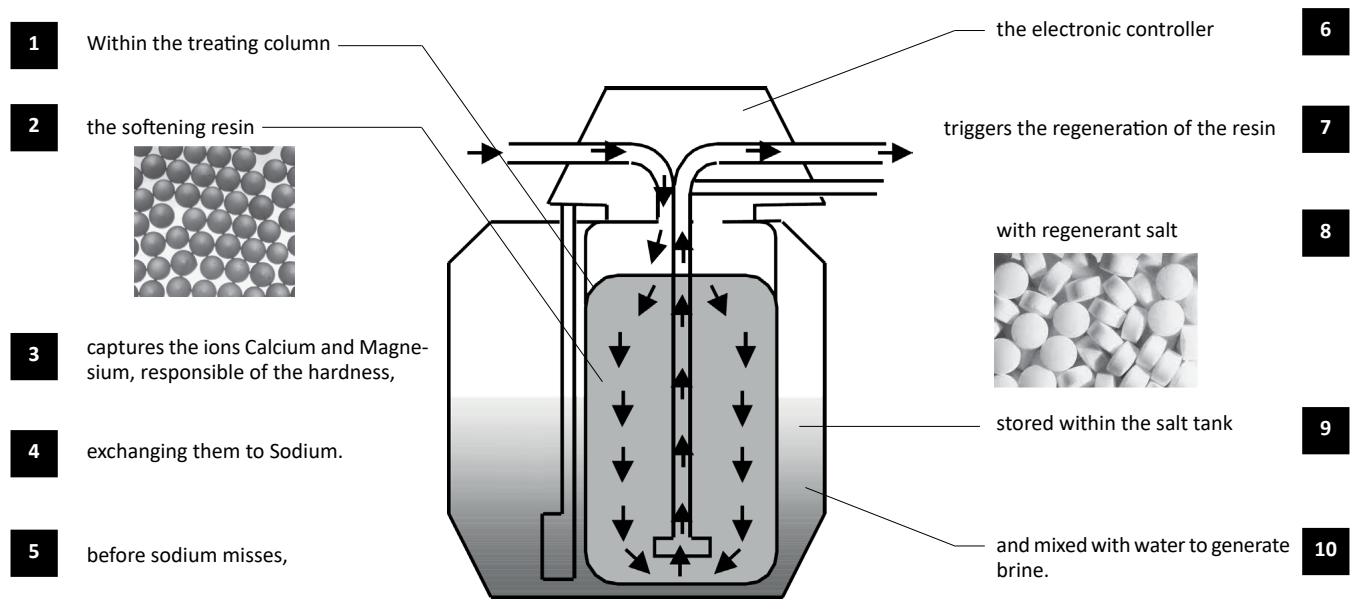
SOFTENER WORKING PRINCIPLE
A softener works as shown in the diagram here below:
INSTALLATION - OVERVIEW
The softener installation involves the elements listed and pictured here below. Please refer to the Scope of Delivery sheet, which specifies which elements are delivered with your softener.
- Softener
- Controller unit
- Salt tank
- Salt tank lid
- Brine valve
- Power supply
- Pre-filter
- Drain tube
- Brining tube
- Salt tank overflow
- Siphon
- Bypass
- Hoses In/Out mandatory
- Tap for gardening usage
- Clamps 1
It is under the installer's responsibility to make sure that the installation does not generate any water hammer which could damage the proper work of the softener.
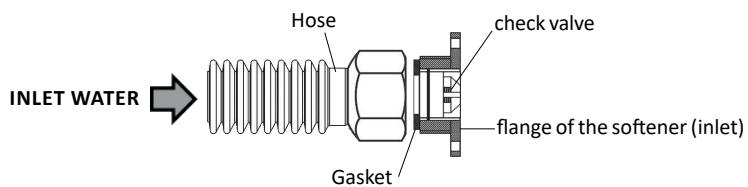
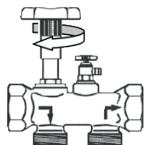
Our softeners are equipped with a check valve on the water inlet connection flange. The check valve may exit the flange under extreme operating and mounting conditions. To avoid this phenomenon, it is mandatory to connect the softener with flexible hoses (according to diagram here below).
We also recommend to install a leak detection system (e.g. BWT AQASTop).
CAUTION : Do not insert a reduction or an adapter between the softener connection flange and the flexible hose. The flexible hose of the same diameter as the flange must have a gasket that keeps the check valve locked in its housing.
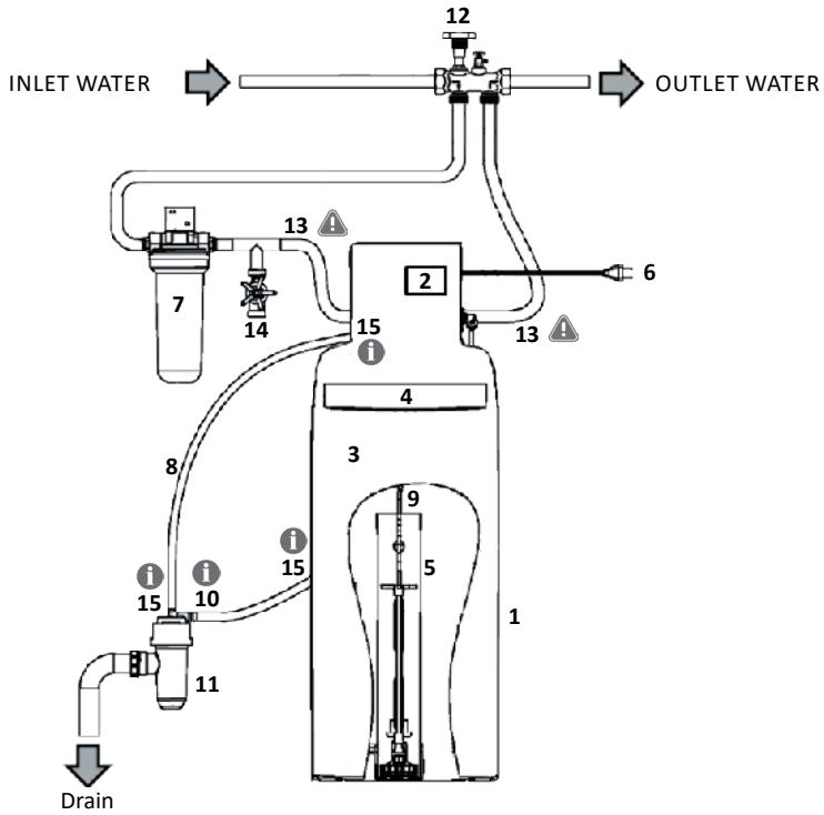
The numbers in bold refer to the marks in chapter INSTALLATION - OVERVIEW
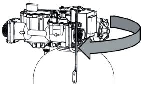
Tighten the hydraulic block
The preliminary tightening of the hydraulic block upon the vessel is crucial because untightening during transportation may have occurred.
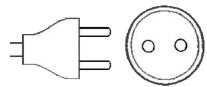
Check the power outlet
Check that there is a power outlet of 230V at less than 1.20 meters.
Install the pre-filter (7)
Place and connect the filter upstream from the softener.
Comply with the water flow direction as shown on the filter head.
Fix the filter head on the wall with the bracket, without tightening too much the screws on the filter head.
Put the softener (1) in place
Place the device in its definitive position (see dimensions on the Scope of Delivery sheet)
The floor shall be clean and horizontal.
The controller unit (2) and the lid shall remain accessible.
Check the network pressure
The pressure must be within the limits indicated in the additional sheet. Above 7 bars, install a pressure reducer.

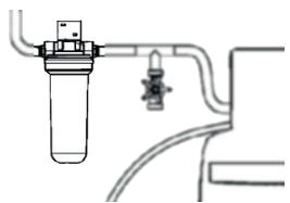
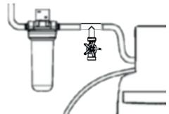
Insert a tap for non-softened water (14)
In case you need to keep raw water (for example for gardening, etc.)
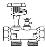
Install the by-pass (12)
Note: the shown by-pass is wall-mounted single block brass by-pass
Install the bypass on the pipe complying with the water flow direction.
Turn the bypass tap into the softener by-pass position.
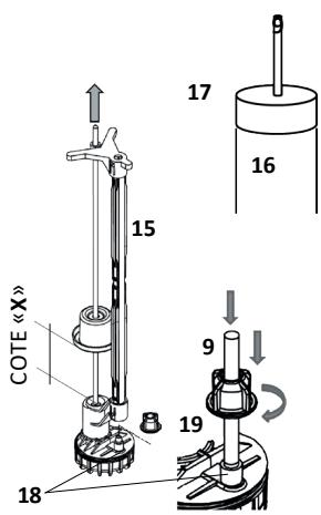
Set and connect the brine valve (5)
Open the salt lid (4), remove the cap (17), then the brine valve (5) from its well (16). Set the float height (X), rod pulled, at the value provided on your Scope of Delivery sheet.
Check that the brining tube (9) is cut straight on its ends, put it on the sheath (15), then tighten it on the fitting located on the brine valve foot (18), using the fly nut (19). Put the brine valve (5) back into the bottom of the well (16), pass the brining tube (9) through the hole of the cap (17), then put this cap back upon the well (16).
Pass the brining tube (9) through the dedicated hole in the salt tank, making sure that this tube does not bend anywhere.
Connect the hydraulic block
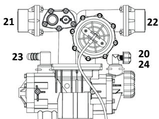
Connect the brining tube (9) to the quick fitting (20).
Connect the in and out flexible hoses (13) respectively on the flange fittings (21) and (22) of the hydraulic block.
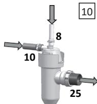
Connect the drain tube (8) on the splined fitting (23) and tighten it with a hose clamp (Serflex type). Connect the plug of the chlorination cell if your softener has this option (24).
Connect drain outlets.
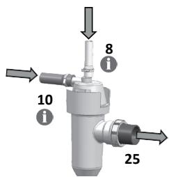
1 Connect the drain tube (8) to the upper fitting of the siphon (11) and tighten it with a hose clamp (Serflex type). The siphon ensures the mandatory protection of the domestic water circuit against sewage backflow.
1 Connect the tube of the salt tank overflow (10) to the side fitting of the siphon (11), respecting a slope of minimum 2% (2 cm per meter) from the tank overflow to the siphon. Then tighten it with a hose clamp (Serflex type).
The overflow must take benefit of gravity and follow a simple and short way. If not possible, install a lift pump compatible with salted water.
Connect the siphon (11) to the drain by a rigid PVC tube with a diameter of 40mm , tightened on the fitting (25).
Complete the connections and purge the air.
Before opening the water inlet into the installation, purge and rinse properly the pipes upstream from the bypass.
Connect the inlet and outlet flexible hoses (13) to the network pipe, by paying attention to the water flow direction.
Progressively open the bypass tap (or the upstream cutting valve of the installation).
Purge the remaining air by using the purging screw upon the filter (unscrew it, then screw it back once the air is purged) or by a downstream tapping point if the filter is not equipped.
Plug the softener to the electricity outlet.
SETTING
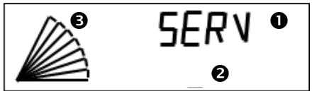
At its first start-up, the device displays after a few seconds the message SERV, first step of the setting, which uses 5 keys:
| Key | Name | Function |
| ←M | Left / Menu | • Activates the menu with a long press (5 seconds)
• Ongoing setting cancellation without record |
| ↓ | Down | • Down move within a list of choices
• Decrease / change of a parameter |
| ↑ | Up | • Up move within a list of choices
• Increase / change of a parameter |
| → | Right | • Move from left to right digits (example: hours to minutes)
• Information on the salt level during filling |
| OK | Enter | • Enter into a menu
• Setting validation
• A long press (5 seconds) triggers a manual regeneration. During this process, a brief press forces the trigger of the next step. |
The following steps are necessary and sufficient to set the softener.
You just need to know the hardness of the raw water (concentration in lime scale), measured before or known from the public water distribution network.
First press 3 seconds on the key M, until the message LANG appears on the display.
| Step n° | Message displayed | Purpose | How to do |
| 1 | LANG
- - | Change language if necessary | Default value is French
OK to change
←M to cancel |
| FR
- - | Language selection | ↓↑ to select
OK to confirm
←M to cancel |
| 2 | HOUR
00:00 | Time setting : hours | ↓↑ to change
→ to go to minutes
OK to confirm
←M to cancel |
| MIN
15:00 | Time setting: minutes | ↓↑ to change
→ to go back to hours
OK to confirm
←M to cancel |
| 3 | TYPE/SALT
tAbl | Specify the type of salt for some devices | ↓↑ to select
OK to confirm
←M to cancel |
| 4 | VOLUME
16 L | Specify the resin volume within the softener, in liters. | ↓↑ to select
OK to confirm
←M to cancel |
| 5 | HARDN
°F | Hardness unit choice:
°F or °dH | ↓↑ to select
OK to confirm
←M to cancel |
| IN
30°F | Enter the inlet hardness
(unit may be °dH) | ↓↑ to select
OK to confirm
←M to cancel |
| OUT
5°F | Enter the outlet hardness
(unit may be °dH) | ↓↑ to select
OK to confirm
←M to cancel |
COMMISSIONING
RINSING
The softener displays the message: REGE?
Press the OK key (once or 3 times, depending on your model). REGE 1 is displayed and a complete regeneration starts.
Progressively open the bypass tap water flows from the hydraulic block to the drain through the evacuation tube. Let it flow in order to fully rinse the softener.
Stop this rinsing by pressing OK during 5 seconds. Then SERV is displayed on the screen.
RESIDUAL HARDNESS SETTING
The hardness is measured in degrees (French °f or German °dH degrees)
1^ = 10 milligrams of "lime scale" in one liter of water
1^ = 1.78^
The hardness measurement is done with a kit of reactive stripes or colored reactive liquid. See further, in the chapter Routine maintenance.
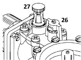
It is possible to blend the softened water produced by the device with raw water, using a blending unit located on the rear side of the hydraulic block, in order to reach a residual hardness of few degrees (value depending on the country habits).
First, turn counterclockwise the knob (26) at its maximum. Then screw the knob (27) until it reaches its lowest level. Thus the outlet water is fully softened (hardness = 0°)
Then turn clockwise the knob (26) of half a turn. The outlet water is then slightly blended with raw water.
Slightly open any tap downstream from the softener (or use the sampling tap of the bypass) and measure the water hardness at this point. Use the knob (26) to tune the hardness for low consumption flow rates:
For hardness tuning at high flow rates, largely open a tap downstream of the softener and measure again the hardness.
Use this time the knob (27) to tune the hardness: - Unscrew to increase it
NOTE: it is under the user's responsibility to define the residual hardness compatible with the equipment installed downstream of the softener.
OPERATION
SALT REFILL
The device uses regenerating salt, dedicated to softening. The salt tank bottom shall always be covered by solid salt over its whole surface. Please refer to the Scope of Delivey sheet in order to know the salt storage capacity of your softener, and to the chapter TECHNICAL FEATURES to know its salt consumption per regeneration.
Concerning the softeners with salt level follow-up by smartphone app:
After every salt refill, enter the salt level so that the app may follow it up.
- Check the salt level once the refill is done, on the scale inside the salt tank
- Press 5 seconds the key to see LEVEL on the display
- Select the salt level with and keys
- Confirm with OK
AUTOMATIC DISPLAYED MESSAGES
The displays show:
an upper information line
a lower information line
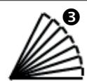
a bargraph with 10 segments, showing the remaining autonomy of the softener before the next regeneration, by steps of 10% . The graph in this example shows 70% remaining autonomy. For each operation step of the device, the displayed messages are as follows:
SERV
2
| SERV | Alternate with | 968 | The device is in service: it delivers softened water. Its treatment autonomy before regeneration is here 968 liters. |
| REMPL 375 | | Water is being poured into the salt tank (see chapter ADVANCED SETTING), it will end in 375 seconds. |
| SAUM 180 | | The brine is under preparation in the salt tank for the next regeneration; this step will end here in 180 minutes. |
| REGE 1 00:45 | | The softener is going through its first active regeneration step, which will end here in 0 minutes and 45 seconds. |
| REGE 2 18:35 | | The softener is going through its second active regeneration step, which will end here in 18 minutes and 35 seconds. |
| REGE 3 02:15 | | The softener is going through its third active regeneration step, which will end here in 02 minutes and 15 seconds. |
| CHECK | Alternate with | SALT | The softener detects a lack of salt and advises to check the salt level in the salt tank. |
| STD-BY 12:30 | Alternate with | 968 12:30 | The regeneration function is OFF (see Stand-By mode next page). The softener delivers soft water as long as its autonomy allows it (here: autonomy of 968 liters). |
MANUAL REGeneration
At any time, it is possible to trigger the regeneration of the softener, via the long press (5 seconds) on the OK key.
If this is done for a test purpose, it is possible to manually go from one step to the next by briefly pressing the OK key.
SALT ALARM ACKNOWLEDGEMENT
When no salt is left in the tank, the device displays the alternate words SALT and CHECK.
Once the salt refill is done, you may just wait for the next regeneration to let this alarm disappear. It is recommended though to acknowledge immediately the alarm, following these steps:
- Proceed with a long press (5 seconds) on the M key
- Then briefly press this M key to go through
the menus until the display shows this one:
CHECK / SALT (alternate)
On
- Press once on or key to make OFF appear on the lower line
- Press OK to confirm
- Press M during 5 seconds to quit the menu: the alarm shall disappear
POWER CUT
In case of a power cut during a regeneration, this process restarts at the beginning of the ongoing step. In case of a power cut during service, the softener will restart also in service.
STAND-BY MODE
It is possible to prevent the softener from going through a regeneration, automatic or manual. This might be useful, for example, while you are
waiting for the intervention of a technician in case of technical problem. Therefore:
- Proceed with a long press (5 seconds) on the M key
- Then briefly press this M key to go through the menus until the display shows this one:
STD-BY
Off
- Press once on or key to make ON displayed on the lower line
- Press OK to confirm
The display shows then the message STD-BY alternating with the softener autonomy value.
To cancel this function, you just have to come back to this STAND-BY menu and turn the lower line into OFF.
ADVANCED SETTING
Accessed by the code 23, then the browsing works in the same way as the regular setting mode. The intervention on the advanced setting shall be done by a trained professional. Any mistake can disturb the work of the device and is under its author's responsibility.
| Step n° | Display | Purpose | Action |
| 0 | PASSW ? 00 | Enter the password to go through the advanced setting. | ↓↑ to change OK to confirm ←M to cancel |
| 1 | STATIS | Activation or not of the statistic volume | ↓↑ to change OK to confirm ←M to cancel |
| 2 | PROP R On | Enable / disable the proportional regeneration. | ↓ to turn on / off OK to confirm ←M to cancel |
| 3 | CAPA 80 | Modify the softening capacity of the device, which has been automatically set once the resin volume was selected (step 3 of regular setting). | ↓↑ to change OK to confirm ←M to cancel |
| 4 | CONSU 71 | Adjust the water consumption per full regeneration. Only for devices with the salt level follow-up by smartphone app. | ↓↑ to change OK to confirm ←M to cancel |
| 5 | SALT 2000 | Adjust the salt consumption per full regeneration. Only for devices with the salt level follow-up by smartphone app. | ↓↑ to change OK to confirm ←M to cancel |
| 6 | VOL OK 856 | Volume of softened water (read only info). Here: 856 liters. | ←M to go to next step |
| 7 | PEAKFL 1068 | Peak flow recorded since the last regeneration (read only info). Here: 1068 liters per hour. | ←M to go to next step |
| 8 | N REGE 48 | Number of regenerations done since the commissioning. May be reset. | ↓↑ to change OK to confirm ←M to cancel |
| 9 | CHLOR Off | Enable / disable the chlorination function | ↓↑ to change OK to confirm ←M to cancel |
| 10 | ALARME Off | Salt lack alarm enabled / disabled | ↓↑ to change OK to confirm ←M to cancel |
| 11 | SAFE L 2 50 | Safe level value = remaining capacity value which triggers the regeneration once reached. | ↓↑ to change OK to confirm ←M to cancel |
| 12 | REGE T 2:00 | Time of regeneration start. | ↓↑ to change OK to confirm ←M to cancel |
| 13 | PRESS 4 | Water network pressure. To be set for proportional regeneration purpose. | ↓↑ to change OK to confirm ←M to cancel |
| 14 | FUL RG 5 | Frequency of the full regenerations (to prevent from loss of capacity occurring with time), for the softeners with proportional regeneration function. Here: one full regeneration every 5 regenerations. | ↓↑ to change OK to confirm ←M to cancel |
| 15 | STEPS | Setting of each regeneration step durations. The followings step durations can be adjusted (one submenu for each): Backwash (BACKW); aspiration (ASPI); fast rinse (FAST); brine preparation (propor. regen.) (BRINE); tank refill (propor. regen.) (REFILL). Caution: If specific times are listed on the attached Scope of Delivery sheet, it is mandatory to set them accordingly, as they correspond to the configuration of the unit. | OK to enter the menu, otherwise ←M then ↓↑ to change OK to confirm ←M to cancel |
| 16 | FORCED NONE | Turn ON or OFF the automatic forced regeneration after a long time without water consumption | ↓↑ to activate OK to confirm ←M to cancel |
| 17 | RESET OFF | Reset back on initial factory settings | ↓↑ to turn ON OK to confirm (twice) ←M to cancel |
This maintenance level may be handled by anybody having carefully taken into account the following guidelines. It is highly recommended to follow them so that the softener keeps its performances in the long term.
| Maintenance guidelines | Frequency and consumables |
| Check the salt level in the tank | Every week, or if alarm. Refill as far as needed. Concerning the devices with the salt level follow-up by smartphone app: keep in mind to enter the salt level reached after refill, as explained in the chapter OPERATION |
| Setting check | Check the time on the display. |
| Time change | The seasonal time change is not automatic. Change the time following the procedure explai-
ned in the chapter SETTING. |
| Change the filter element of the filter (7)
There are various models of filters. To change
the filter element:
• Cut the water upstream and downstream
• Let the pressure drop with the purge
screw upon the filter
• Unscrew the filter transparent bowl and
remove the filtering consumable
• Replace it by a new one
• Screw the bowl back, tightening it gently | Every 6 months or more often if you notice a
significant pressure drop at the taps. |
| Overall checkup, cleaning, protection
• Use the AQA clean pack or equivalent,
providing the adapted products and spe-
cifying their proper use in its manual.
• Check the raw water hardness upstream
and the softened water hardness
downstream of the device, using the
analysis kit. | Once a year:
- Pack AQA clean including:
• Hardness kit
• Cleaning liquid
• Resin protector
- Standalone hardness kit
- Standalone cleaning liquid |
For a durable performance of the device, the following key points shall be yearly checked by a professional. Please read the manufacturer's web pages dealing with Service, to find the proposed service contracts and the checks they include.
MAINTENANCE CHECK LIST
- Check the water hardness up- and downstream from the softener
- Check controller settings
- Check and clean (if needed) the brining line (replacement if worn or damaged)
- Check and clean (if needed) the salt tank
- Check inner components (replacement if worn or damaged)
o Inlet filter
o Injector
o Moving parts: solenoid valves, membrane, inner valve shaft
o Wire of the water meter
o Chlorination cell (on models with this option)
o Proportional regeneration block (on models with this option)
TROUBLE SHOOTING
| Issues | Root causes | How to fix |
| The displays shows alternative CHECK and SALT | There is not enough salt left in the tank OR The device detects a regeneration flaw. | Refill the tank with salt.
If it does not look to need refill, contact the technical service. |
| The recorded time is wrong. | The seasonal time change has not been done OR A power cut occurred and the data recovery did not work (battery KO). | Reset the timing (see chapter SETTING).
If the problem comes up again, contact the technical service. |
| No display | The power is off OR There is an electric or electronic failure. | Check the power outlet where the device is plugged.
If the power outlet works, contact the technical service. |
| Water flow through the evacuation tube (8) | The device is regenerating (which means that there is no problem) OR The internal components meet a failure. | Check that the device displays REGE 1, REGE 2 or REGE 3.
If not, contact the technical service. |
| Water overflow from the salt tank (10) | The brining chain does not properly close or leaks. | Check the connection between the bring tube (9) and the brine valve (5).
If the problem remains, contact the technical service. |
| The water delivered by the device does no longer look softened (lime scale coming back, etc.) | Many possible root causes. Step through all the checks on next column. | Measure the residual hardness once first, then after each of the following steps until the result is OK.
Check that the bypass is open to direct the water to the softener. If not, change its position.
Check that there is still salt in the tank. If not, refill it.
Check if the type of salt is well selected in the programming.
Check that the filter element is not clogged. If so replace it.
Go again through the blending procedure (see chapter COMMISSIONING)
If the problem remains, contact the technical service. |
| The connection to the Best Water Home app cannot be established. | No recognized signal between softener and smartphone | Check the connectivity activation on the smartphone.
Use a compatible smartphone running a recent version of Android or iOS.
Make the 1st connection within 70cm of the softener head.
For the following ones, the distance depends on the environment, but can exceed 12m.
Connect only one device at a time to the softener.
Activate "Disconnect my softener" before trying again.
If the problem persists after 5 attempts, contact customer service. |
APPLICATION USAGE
INSTALLING THE APPLICATION
- Download the "Best Water Home" application and check that all smartphone updates are done.
- Open an account by following the instructions.
- Select the softener from the lists of devices with or without code.
- Activate the smartphone's Bluetooth.
- Start synchronisation in the direct vicinity of the softener in use.
- After a few seconds of synchronization, the application is connected to the softener. The data refresh displays the salt level and water consumption.
UPDATING THE SALT LEVEL
After each salt recharge, press the SEL/SALT button of the softener for 5 seconds. The word "LEVEL" appears on the softener display. Use the up and down arrows to select the salt level reached in the salt tank of the softener as indicated on the scale in the tank well.
Start the synchronization on the application: the salt level is up to date!
TECHNICAL FEATURES
ENVIRONMENT FEATURES
| Features | Unit | All devices |
| Power voltage | V | 230 +10% / -15% |
| Hz | 50/60 Hz |
| Maximal pressure | bar | 7 |
| Recommended minimal pressure | bar | see additional sheet |
| Minimal water temperature | °C | 1 |
| Maximal pressure temperature | °C | 35 |
| Ambient air minimal temperature | °C | Frost free |
| Ambient air maximal temperature | °C | 40 |
OPERATIONAL FEATURES
| Resin volume | liters | 5 | 10 | 16 | 18 | 20 | 22 | 28 | 40 | 55 | 70 | SP05 | SP20 |
| Salt consumption per regeneration | kg | 0,50 | 1,25 | 2,00 | 2,25 | 2,50 | 2,75 | 3,50 | 5 | 6,87 | 8,75 | 0,50 | 2,00 |
| Softening capacity for 15°f hardness drop of (around 8.5 °dH) | liters | 1650 | 2300 | 4800 | 5200 | 5300 | 5900 | 7500 | 13000 | 18000 | 23000 | 1250 | 6000 |
| Softening capacity for 20°f hardness drop of (around 11 °dH) | liters | 1250 | 1800 | 3600 | 3900 | 4000 | 4400 | 5600 | 10000 | 13000 | 17000 | 950 | 4500 |
| Softening capacity for 25°f hardness drop of (around 14 °dH) | liters | 1000 | 1400 | 2900 | 3100 | 3200 | 3500 | 4500 | 8000 | 11000 | 14000 | 750 | 3600 |
| Softening capacity for 30°f hardness drop of (around 17 °dH) | liters | 800 | 1200 | 2400 | 2600 | 2700 | 2900 | 3700 | 6600 | 9100 | 11000 | 600 | 3000 |
| Softening capacity for 35°f hardness drop of (around 19.5 °dH) | liters | 700 | 1000 | 2100 | 2200 | 2300 | 2500 | 3200 | 5700 | 7800 | 10000 | 500 | 2600 |
| Softening capacity for 40°f hardness drop of (around 22.5 °dH) | liters | 600 | 900 | 1800 | 1900 | 2000 | 2200 | 2800 | 5000 | 6800 | 8700 | 450 | 2200 |
| Average water consumption per regeneration | liters | 50 | 60 | 70 | 70 | 100 | 100 | 120 | - | - | - | 50 | 160 |
| Electrical consumption in service | 6 VA |
| Electrical consumption in regeneration | 25 VA |
(1) - The above data are given for a network water pressure of 3 bars and the factory settings.
(2) - The softening capacity in the above board is the volume 100% treated.
If any data is missing from this manual, please refer to the additional sheet.
CHECK/ZOUT(wisseled)

MOHTAX-OBLNE CBEDEHNA. 35
MOHTAXK. 36
ПОНРAMMЮВАНЕ... 37
HaCtpoiKa OCTaTOUHO JKeCTKoCTN BObl.37
3KcPJIyATAUaIa 38
Pobtophoe 3aOpIeHne coJIbIO. 38
ABTOMATUNCHECKOE OTOBPAXHEHIE
COOBUHNI HA DCNPIEE. 38
PerenepaiaBpyHOMpeKIme. 38
PoiTbepeHne noluyehn cunHaIOB
O HexBaTke cOlI. 38
OTKIIoueHne nHTaHn. 38
PexnM oXnDaHnA. 38
PACUINPEHHOE IPOPGAMMPOBAHNE..38
IIAHOOBTEXOBCJYKUBAHNE.39
PABOTACXIMMUECKMNPEAHTAMN
YctaHOBHTe fHJIbTp npeBaPHTeIbHOI ONUCTKN, (no Heo6xOaMOCtN)(7)
UCTAHOBITNE NQDKIOUHTE DO YMRAHTEJIA
ФИЛБТР ПЕДВAPITELHON ONUCTKIN, ECN 3TO
HEO6XODIMO.
CobnDaiyeuKazAHneOHaNPaBHeHHN DInBeJHNe BObl, npBVeJeHHOe Ha rONoBHOu ChaTnФnlbtrpa.
3aKpeNITE roIobHyIO uactb fNtpa HA cTeHe npn NOMOu KOHCOIN, He 3aKpyNBaRa Ha Hei BnHTbI CInuKOM PLOTHO.

UctaHOBHTe KlananH-6aHnac, ecn3TO Heo6xOdmo (12)
PnmeaHae;HaIJIIOCTpaUm NOKa3AH LaYHHbOJ OAnHO6IoHbN KlnaH-6aHnac HAcTeHHORo KpeINHeJA.

YctahOBHTe yMraHTeIb (1) B npEHa3HaueHHOM dIy Hero MeCTe
UctahOBHTe np6Op B OOKHateIbHoe noLOXHeHne (CM. pa3Mepbl BJIncTe «KomPNeKT nOCTaBKn)
KoHTpOJIneP (2)ИКрblIshka (4)ДОЛЖнbl OCTaTbCЯ Ha DoCTyIHHOMpacCTOJHIN

UctaHOBHTe Klananh-baiNac Ha Tpy6e B COOTBeTCTBnC HnnpabLeHnEM DnJKeHHB ODoI
IopKJIIOUHTe IpeHaxHbIe BbIXObl
CoeHHnTe IpeHaxHyIO Tpy6y (8) c BepxHM fHTINHOM CnFOHa (11) nIIOTHO 3aKpENITE eO npI NMOUIN XOMyTa UJHra (muna Serflex)
CmD0H ObecneYBaET O63aTeIbHyTO 3aUHTy b6tIOBTo BOOpBOHOHO C9eT OT o6paTHOrO pNtTOKa BOBy I3 KaHaJIIN3aUN
CoéHInTe nepenBHOI NaIpy60K coJIeBOr 6aKa (10) c 6oKoBbIM ΦHTINrOM CnOHa (11), COXPAHRe He MeHee, YcEM 2% YKJIOH (2 cm Ha MeTp) ДЯпrelenBa n3 6aKa B cnOHa. 3aTeM ПIoTHO 3aKpeNte erO npri NmOOni xomYta shaHa r (muna Serflex)
IpeenBdoJKeH npoxoINTb ecTeCTBeHHO, noI deJeCTBnEM TpaBHTaUNi, MaKcMnAJIbHO IpOcTbIM I KOpOTKIM NpTeM. EcIN 3TO HeBO3MOxH0, yCTAHOBtNE ToJbEmHyIO HaCOCHyIO yCTaHOBYK, COBMecTHMyO C coJeHO BDOJ.
CoeHInHTe CnΦOH (11) c dpeHaKOM pnp nmoOnxjcTcKoi PBX TpybI dIaMaTePOM 40 MM, pIoTHO 3aKpeHHeHHo HaΦHTnHre (25)
3aBepuTe Bce Tpe6yemblie NOdknUoyenH n CtpaBnte Bo3dyx
Ipei Te, KAK OKpbTb DoCTyn BObl B yCTaHOBky, IpOuHCTnTe H IpOMOnTe Tpy6bl, HaxoJaUneCra Bble Klaapana-6aunaca no TeueHnO BObl
IopKIOHnTe BxOHBie N BbIXoHNbIe Tn6Kne IJHaHn (13) K cTeBOI Tpy6, C yUeTOM HAnpaBHeHn DINXKeHn BODbI
IocTeHNO OTKpOte KpaH KJIanaHa-6aInaca (iJn 3anOpHbKJIanaH yCTaHOBKn, HaxoJusinCBy BbIe n o TeueHIO BObl)
CtpaBnTE ocTbuiNcra Bo3dyx npn NOMOUI BnHTa pOpyBkHa qHJIbTppe (pa3BnHTnte ero, 3aTeM - cTpaBnB Bo3dyx - 3aBnHTnte ero CHOBa) nIi TOnKoi OTbOJa HIXe No IIOTOky, ecIn qHJIbTp He oOpydObaH.
BkIIOUHTe BUNKy IITAHN yMgYNTeINB pO3ETky NITAHN.

ПОТРAMENTSOBAнE
Pn npBOM 3anycke np60pa B 3KcNpyatauHn ha ero dinCIIee, uee3 HeckolbKO cekyHd noRbTc CnHrAN «SERV». 3To - nepBbI 3tan nporpamMnpoBaHn npaMeTpoB ero pa60tbl, pn KOTOpOM bbl MoKeTe HcNoIb3OBAb5 KlaBvI:
IucnneI otpaxaet cledyuooee:
1 -BepxHry INΦopMaUOHHa CTpoka
- HIXHЯ INΦOpMaζNoHHa CTpOKa
3 -инданкатор-шкалac 10 cermetamn; demOHCTpnpyET CTeENb abTOHOMHOCTN, octaUOuOc y YMnHTeIJIpeed cIeDyUoIe peRehepauei (war cermenta: 10% ).B npIMpepe, npBBeDeHNHom haIIIOCTpaun, INHdKNATOP NOKa3bIAaET OCTatoCHYBOtOHOMHOCTb Ha yPOBHe 70%
CnHaIbI,poBIAJIOUJIeCAHaDcNIIee B 3aBNCIMOCTNOT3Tana pa60tI npi60pa:
Ha dncnnee He noBntc:
CHECK/SALT(BuepeyHouemcpeKIme) ON
HcNoJIb3OBAHHe IPOrPAMMbI
YCTAHOBKA IPINIOXEHNA
1.Сачайтприлбени "Best Water Home"и убетистсь,чTo ВсБ ошовеня дд смарТфОна Выноллел�.
2. OTKPOIte aKKayHT, cIeIy IHHCTpyKUJAM.
3. BbIbepnte ymraHTeNb n3 cInska yCTpoiCTB "6e3 KoJa".
4.AkTNBpyuTe Bluetooth Ha cMapTfoHe.
5.3anyctnte cHxpoHn3aunB HenocepdtBeHHo 6n30ctn O T nOlb3yemoro ymrgntela.
6. Послесheckолькinx sekynd синхронизаци npinloжене подкючateя К умягчтello.Обнов lienе данhhbix OTOбражет уровьс coNi paXoD Bovbl.
OBHOBJIeHHe UPOBHcOJIu
Iocne kackdoTo do6ablenia co1n Ha 5 cekynd haximaiTe KhoNky SEL/SALT ha ymraHTeNe. CNoBo"YPOBEHb" no8BnaTcTaHa nDCnPee ymraHTeNa.
Ctpelkamn BBepx n Bn3 Bb6epnte ypoBeHb cOnn B emKoCTn yMaIyTeJIa, kak yka3aHo Na shkaJe 6aka.
3anycnte cInxhpOnH3aunIO B npInoJKeHHn: ypoBeH coJI B aKtuaJIbHOM coCTOAHHHI
TEXHNUECKNE XAPAKTEPNCIKN
3KOLOTNUECKNEXAPAKTEPNCNTUKN
INSTALACJA WODNO-KANALIZACYJNA
WYKORZYSTANIE APLIKACJI
INSTALACJA APLIKACJI
NORMATIVASAPPLICABLES. 66
GARANTIA 66
BWT House, The Gateway Centre, Coronation Road, High Wycombe, Buckinghamshire, HP12 3SU, United Kingdom Phone: +44 1494 838 100 Fax: +44 1494 838 101 E-Mail: Enquiries@bwt-uk.co.uk