PARADIS BLEU - Pool BWT - Free user manual and instructions
Find the device manual for free PARADIS BLEU BWT in PDF.
User questions about PARADIS BLEU BWT
0 question about this device. Answer the ones you know or ask your own.
Ask a new question about this device
Download the instructions for your Pool in PDF format for free! Find your manual PARADIS BLEU - BWT and take your electronic device back in hand. On this page are published all the documents necessary for the use of your device. PARADIS BLEU by BWT.
USER MANUAL PARADIS BLEU BWT
PISCINE PARADIS BLEU
Assembly instructions
INSTALLATION INSTRUCTIONS
To be read carefully and kept for future reference.
1.1 Selecting the site 27
1.1.1 Consolidated soil 27
1.1.2 Number of hours of sunshine 27
1.1.3 Shelter from the wind 27
1.1.4 Privacy and views 27
1.1.5 Lush vegetation 27
1.1.6 Proximity to supplies and outlets 27
1.1.7 Special circumstances 27
2. POSITIONING THE POOL 28
2.1 Marking out the pool 28
2.2 Positioning horizontally along the x-axis 28
2.3 Establishing the reference height 29
3. EARTHWORKS 30
3.1 Tracing out the pool 30
3.2 First excavation 30
3.2.1 Marking out the pool 30
3.3 Second excavation (deep end) 32
3.3.1 Underground water - runoff - water table 32
3.3.2 Hard rock 32
3.4 Pool building on a slope 32
4. UNDERSLAB 36
4.1 The base of the excavation 36
4.2 Lay the base course 36
4.3 Fit the main drain 36
4.4 Positioning the welded wire mesh: 36
4.5 Pouring the concrete 37
5. ASSEMBLING THE WALLS 38
5.1 CORNER PANELS AND SUPPORTING BRACES 38
6. LINER LOCKING TRACK 41
7. INSTALLATION OF POOL FITTINGS 42
7.1 Installation of the various items 42
7.1.1 WM Skimmer 42
7.1.2 Water return and vacuum point 43
7.1.3 Fixed underwater light. 43
8. FITTING THE LINER 44
8.1 Preparation 44
8.2 Fitting 44
9. LINES AND PIPEWORK 45
10. FILLING 45
11.CUTTING OUT THE POOL FITTINGS 46
12. BACKFILLING 46
13. UPPER RING BEAM 47
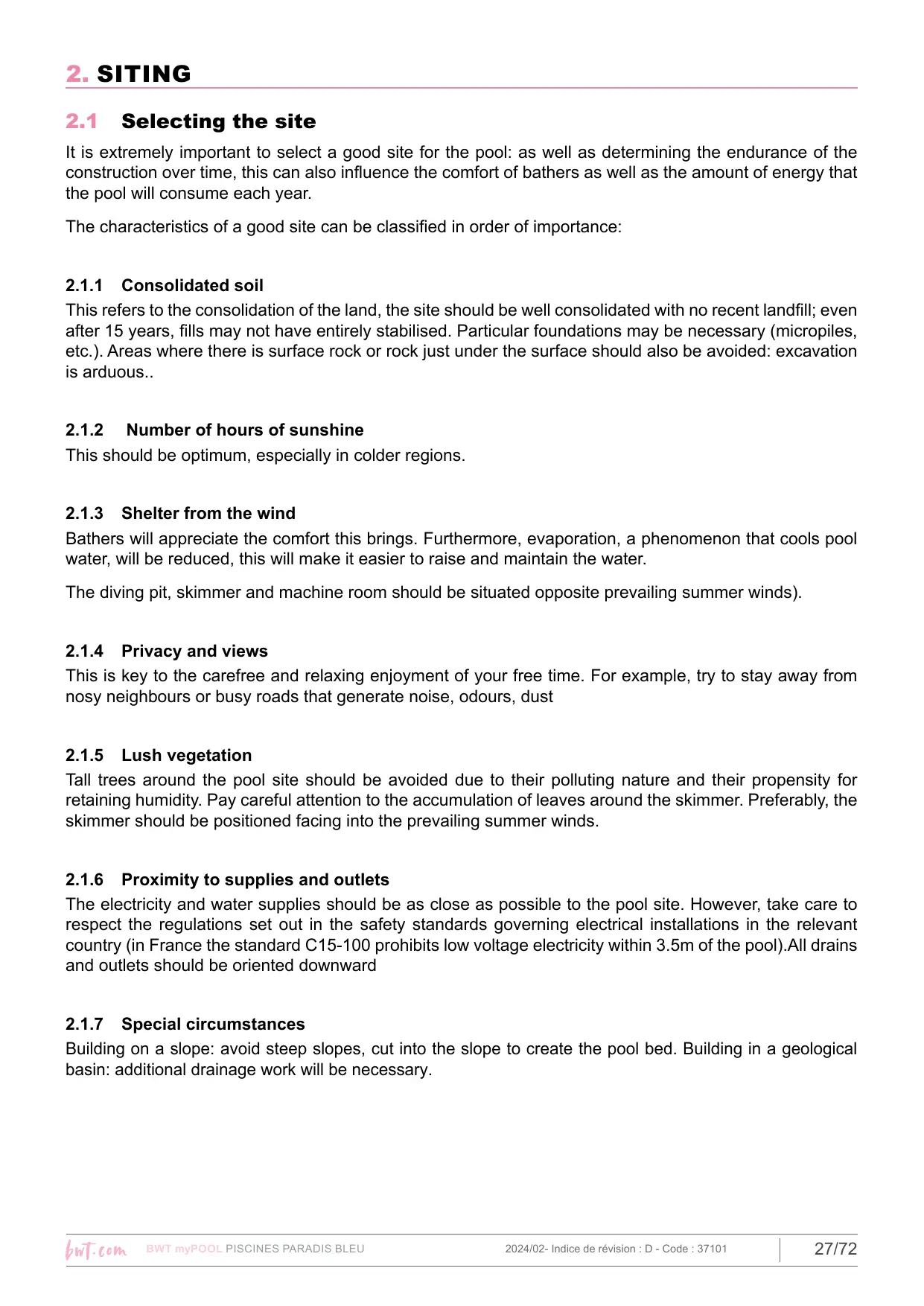
2.1 Selecting the site
It is extremely important to select a good site for the pool: as well as determining the endurance of the construction over time, this can also influence the comfort of bathers as well as the amount of energy that the pool will consume each year.
The characteristics of a good site can be classified in order of importance:
2.1.1 Consolidated soil
This refers to the consolidation of the land, the site should be well consolidated with no recent landfill; even after 15 years, fills may not have entirely stabilised. Particular foundations may be necessary (micropiles, etc.). Areas where there is surface rock or rock just under the surface should also be avoided: excavation is arduous..
2.1.2 Number of hours of sunshine
This should be optimum, especially in colder regions.
2.1.3 Shelter from the wind
Bathers will appreciate the comfort this brings. Furthermore, evaporation, a phenomenon that cools pool water, will be reduced, this will make it easier to raise and maintain the water.
The diving pit, skimmer and machine room should be situated opposite prevailing summer winds).
2.1.4 Privacy and views
This is key to the carefree and relaxing enjoyment of your free time. For example, try to stay away from nosy neighbours or busy roads that generate noise, odours, dust
2.1.5 Lush vegetation
Tall trees around the pool site should be avoided due to their polluting nature and their propensity for retaining humidity. Pay careful attention to the accumulation of leaves around the skimmer. Preferably, the skimmer should be positioned facing into the prevailing summer winds.
2.1.6 Proximity to supplies and outlets
The electricity and water supplies should be as close as possible to the pool site. However, take care to respect the regulations set out in the safety standards governing electrical installations in the relevant country (in France the standard C15-100 prohibits low voltage electricity within 3.5m of the pool). All drains and outlets should be oriented downward
2.1.7 Special circumstances
Building on a slope: avoid steep slopes, cut into the slope to create the pool bed. Building in a geological basin: additional drainage work will be necessary.
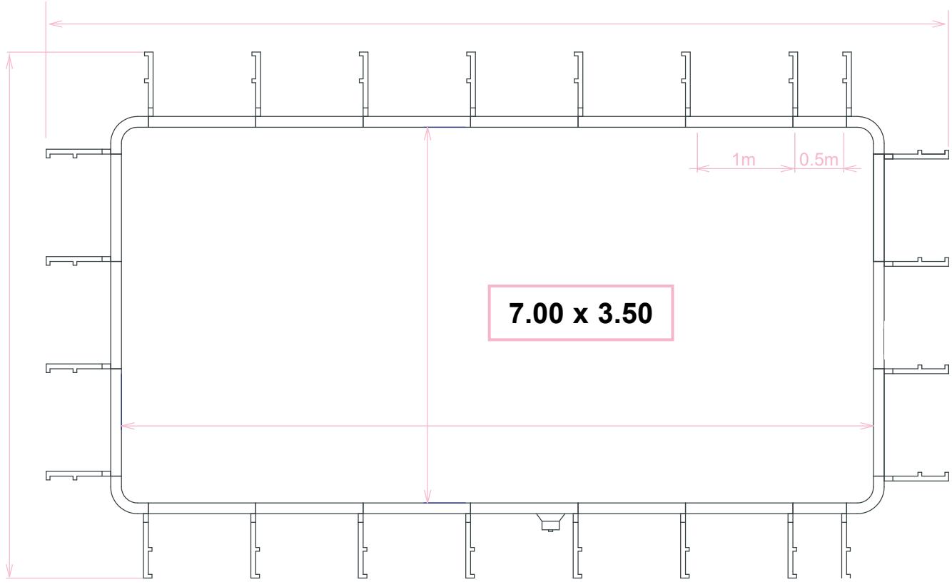
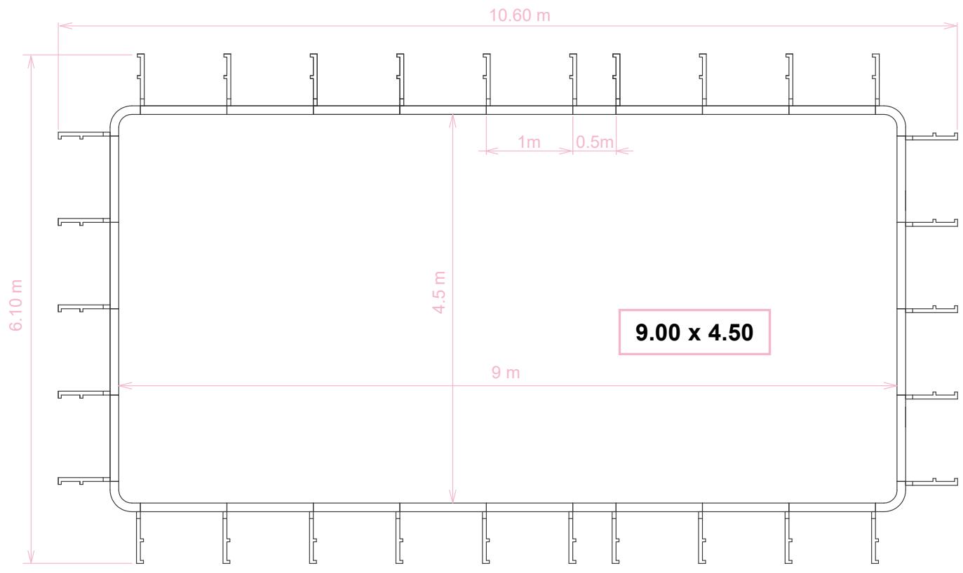
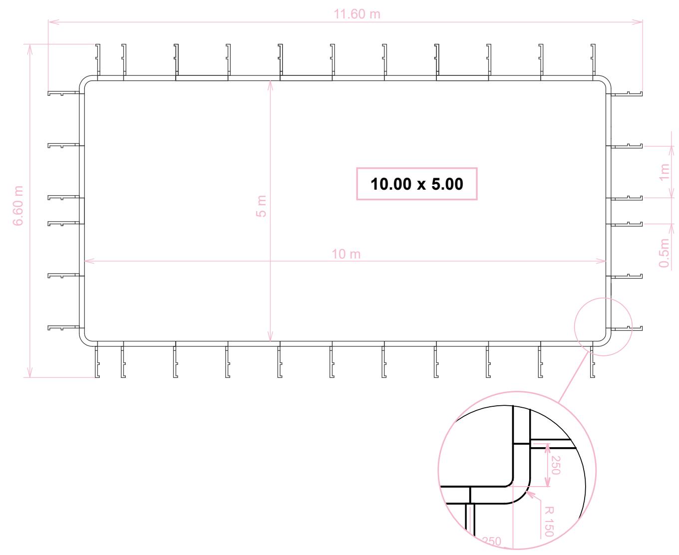
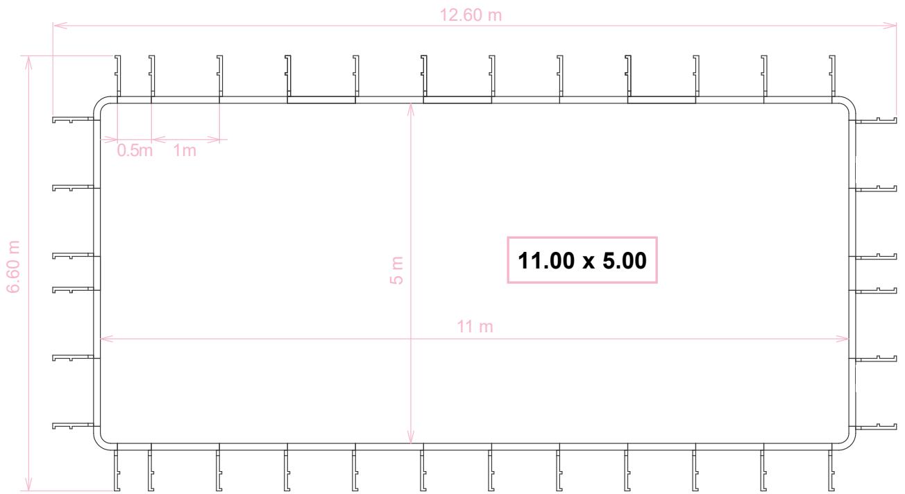
3.1 Marking out the pool
For rectangular Paradis Bleu pools, the rectangle representing the upper surface of the pool is depicted.
That is:
- in terms of its HORIZONTAL position along the imaginary x-axis
- in terms of its VERTICAL position along the imaginary y-axis
Position the pool harmoniously within the lines and contours of the landscape, allow yourself to be guided by logic and visual appeal.
For a better appreciation, stretch an actual-sized tarpaulin on the ground.
3.2 Positioning horizontally along the x-axis
The rectangle should be positioned horizontally with respect to a fixed straight line, for example the side of a house.
By dead-reckoning and with a mason's line, align the rectangle.
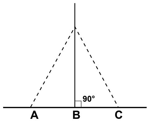
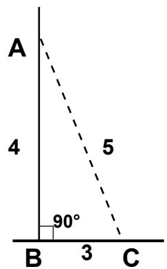
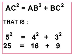
Construct the perpendicular lines using a method such as mediatrices or pythagorus theorem.
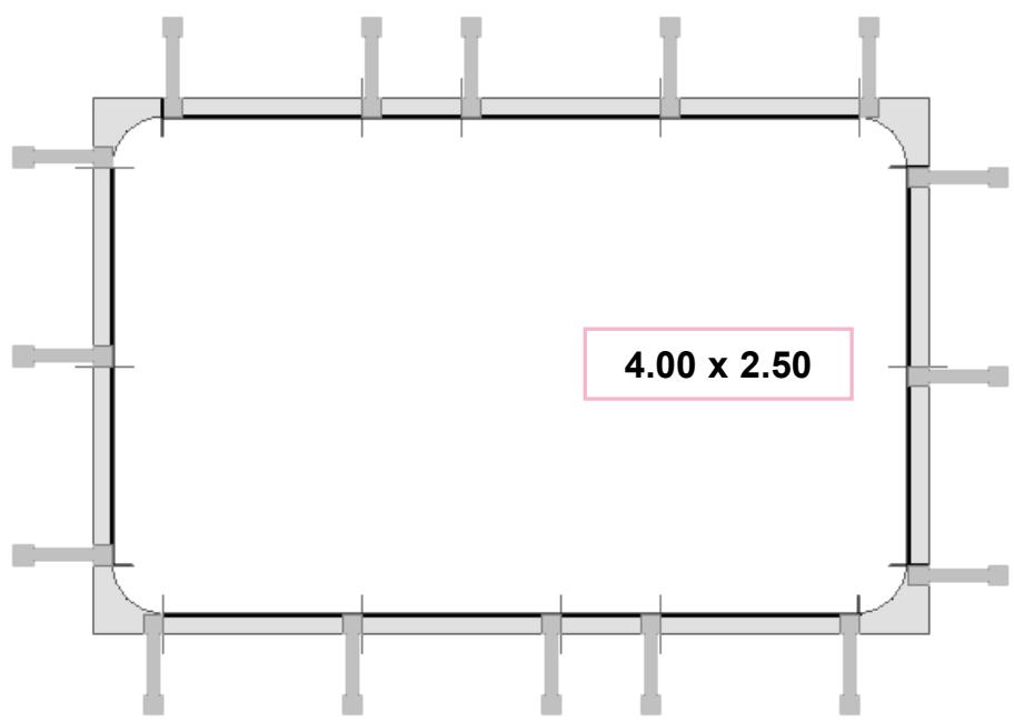
Dimensions
| Pool interior | ||
| Length | Width | Diagonal |
| 4,00 | 2,50 | 4,72 |
| 6,00 | 3,00 | 6,71 |
| 6,50 | 3,50 | 7,38 |
| 7,50 | 3,50 | 8,28 |
| 8,00 | 3,50 | 8,73 |
| 8,00 | 4,00 | 8,94 |
| 9,00 | 4,50 | 10,06 |
| 9,50 | 5,00 | 10,74 |
| 10,50 | 5,50 | 11,85 |
| 11,00 | 5,00 | 12,08 |
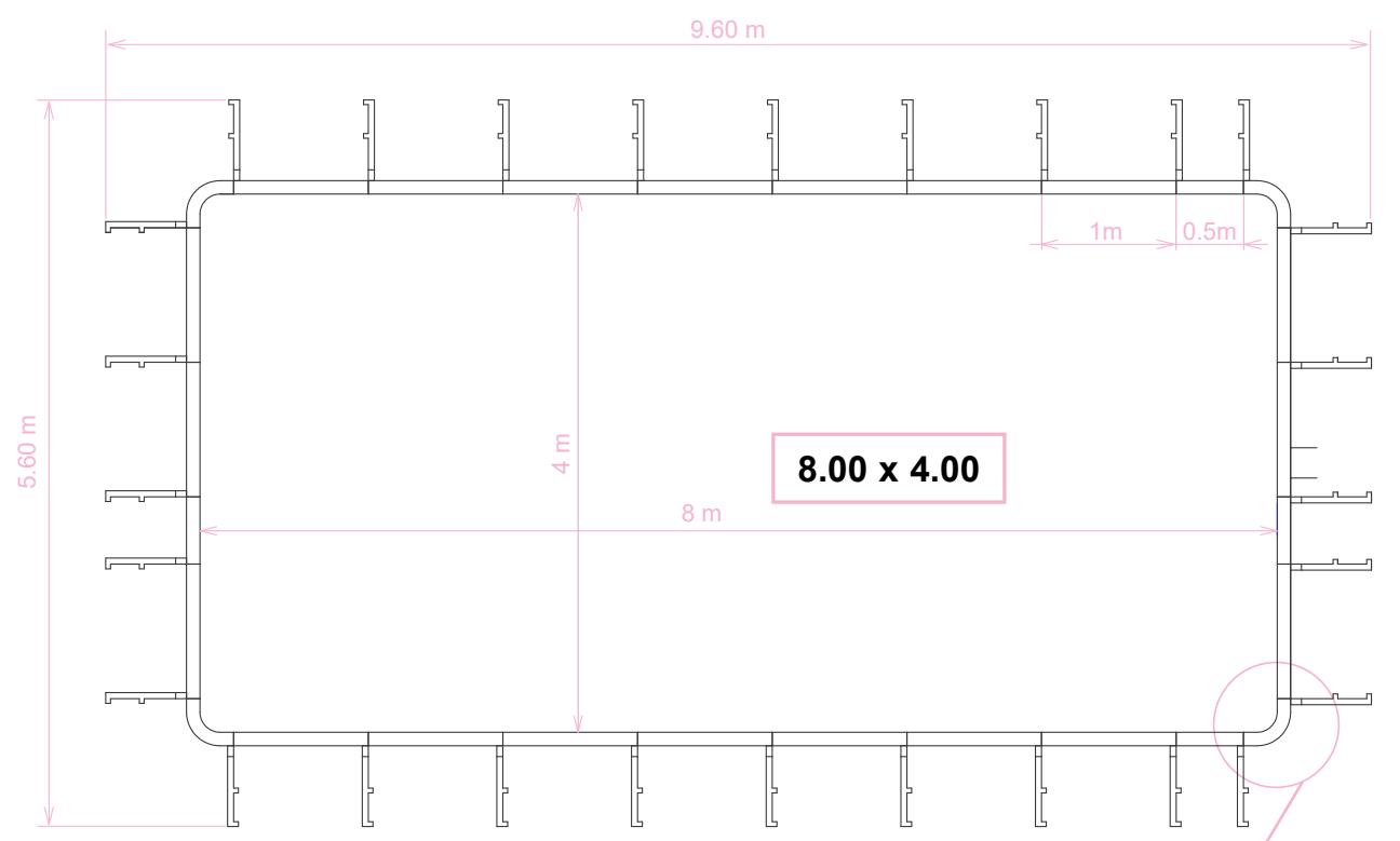
| Excavation dimensions | ||
| Length | Width | Diagonal |
| 5,60 | 4,10 | 6,94 |
| 7,60 | 4,60 | 8,88 |
| 8,10 | 5,10 | 9,57 |
| 9,10 | 5,10 | 10,43 |
| 9,60 | 5,10 | 10,87 |
| 9,60 | 5,60 | 11,11 |
| 10,60 | 6,10 | 12,23 |
| 11,10 | 6,60 | 12,91 |
| 12,10 | 7,10 | 14,03 |
| 12,60 | 6,60 | 14,22 |
Playing on the alignment of the perpendiculars or the parallels, by taking some basic measurements, establish the position of this first rectangle.
Mark out the first edge in plaster
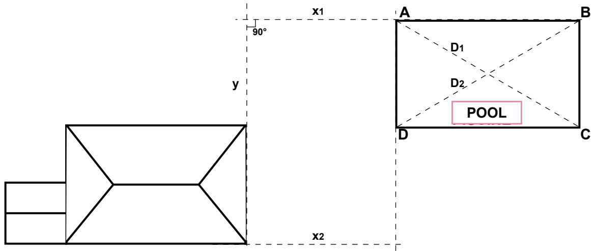
Once one edge of the rectangle has been defined and marked out in plaster, calculate and position the other sides using the diagonals method: if the 2 diagonals of a rectangle are of equal length, the opposite sides are the same length and therefore:
AD = BC ,D1=D2,and hence DC=AB
Mark the rectangle out in plaster
Attach a length of mason's line at one point to trace the arcs of the circles.
3.3 Establishing the reference height
Once the position of the pool has been decided, the pool may be dug. However, before digging the pool, the height differences between the 4 pool corners must be known precisely and the final height of the WATER LEVEL must be carefully considered.
The point A is taken as the reference level or datum point O.
Mark the point on an indisputable reference, for example the top of a stake. Then, using a laser sight (or a large ruler and a spirit level), make sure that the 4 corners of the pool line up with the reference level.
To visualise the final pool water level, stretch some cord between the four corner stakes at the desired height
Notea bene : The builder's level: a large, flexible transparent tube fitted with a transparent graduated section at each end. Fill the tube with water such that the water level is visible in both transparent sections. The water level in both graduated sections is identical when they are at the same level (ensure that there are no air bubbles).
Tracing out the pool
4.1 Tracing out the pool
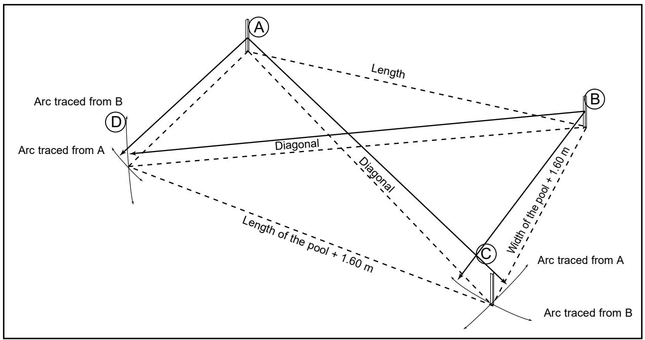
Add 1.60m to the two pool dimensions and plant 4 stakes at the new measurements obtained:
Plant two stakes (A and B) to mark the length of the excavation, (refer to the excavation diagram above: Tracing out the pool).
Using A and B as pivot points and the diagonal and width as the radii, trace 4 arcs to establish the position of C and D as illustrated above. Check that the distance C. D. is equal to the distance A. B. Run mason's string around the stakes and use this as a guide to mark out the excavation in plaster.
Note: It is possible to excavate more precisely, digging out around the supporting braces. This requires a good working knowledge of the installation of Paradis Bleu pools. Refer to the POOL CONFIGURATION diagrams.
4.2 First excavation
Dig out a flat bottomed hole to the depth of the shallow end (or the pool depth if it has a flat base), plus the depth of the underslab (base course + concrete).
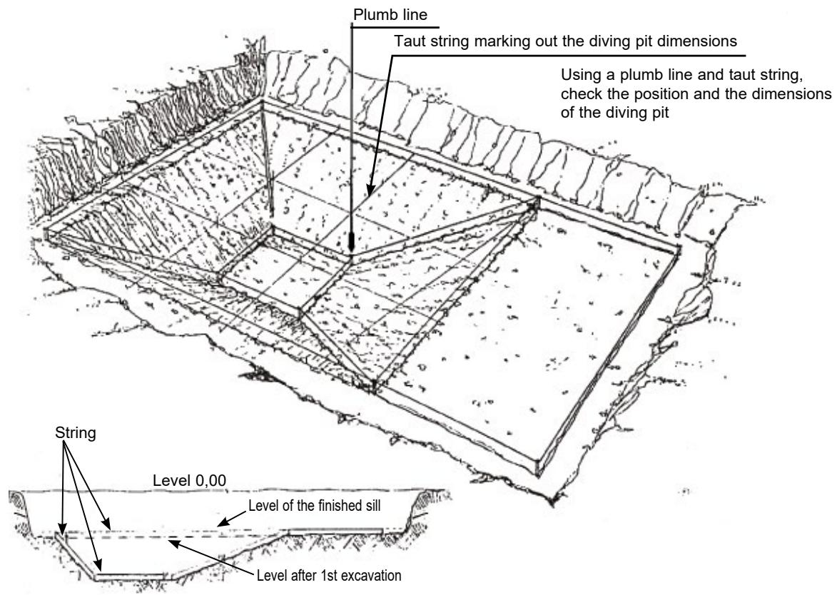
4.2.1 Marking out the pool
Next, check that the base of the excavation is horizontal and that the depth is correct (either using a builder's level and a meter stick, or using a stick three meters long and a spirit level). Mark out the pool by planting 4 corner stakes at the exact corner positions of the pool. Check squaring (the length of the two diagonals should be equal). Run string around the stakes and use this as a guide to trace the perimeter of the pool in plaster.
Note: For flat base pools excavation is now complete. Skip to the section entitled Underslab.
At this stage, refer to the excavation diagram and mark out the dimensions indicated on the diagram according to the pool type.
Marking out a pool with a continuous sloped base
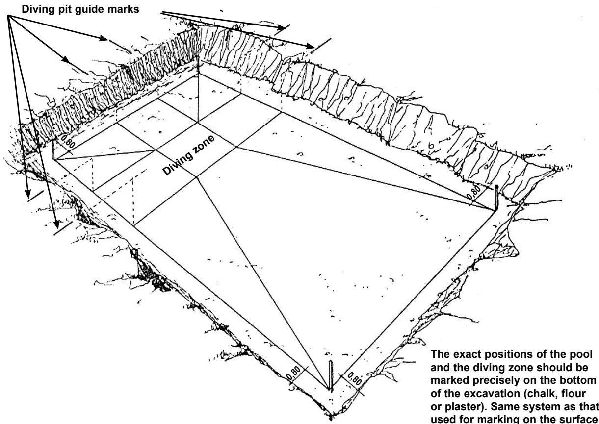
Marking out a pool with a diving pit
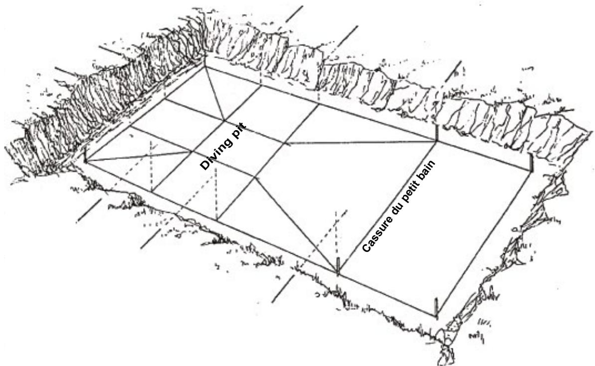
4.3 Second excavation (deep end)
Continue excavation of the pool base. The area of the central rectangle should be lowered to the point indicated on the plan.
The four sides of the diving pit should be sloped (refer to the diving pit diagrams). Using a spade and a pick, finish the slope cleanly.
IMPORTANT NOTE
In the event of accidental overdeepening, that is, the removal of too much earth, the defect should under no circumstances be corrected by adding earth.
The shape may be rectified either using lean concrete, stones, gravel, or at a push, sand. Top soil should never be used, this is prone to compression and could lead to the formation of a vacuum under the pool over time.
4.3.1 Underground water - runoff - water table
Water may be discovered during excavation. This water could be the result of runoff or streaming or you could have hit the water table. Usually runoff or streaming indicates that you have encountered an underground stream whereas standing water indicates that you have hit the water table.
The height of the water table can vary according to the season.
Drain using an appropriate technique (refer to the D.T.P. and the standards applicable in the country of installation - AFNOR in France).
4.3.2 Hard rock
Advise the earthwork contractor of the presence of hard rock so that they may equip the earth moving machine with rock breaking equipment.
4.4 Pool building on a slope
Cut into the slope to create the entire bed of the pool, earth excavated should not be used to enlarge the foundations.
However, the wall on the lower part of the slope may be above ground and may be subsequently backfilled once the proper girding has been installed.
In clay type soils, provide for the complete drainage of the construction: drainage of the sub-bed, along with drainage of the upper peripheral structure.
Diving pit
Rectangular pool configuration
UNDERSLAB
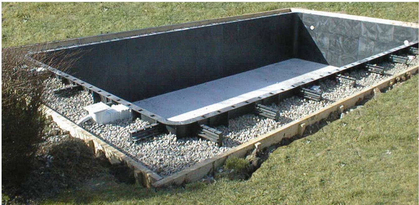
NOTE
The underslab may be poured after the panels are mounted
In this case, the panel structure is positioned, level, on 10 cm blocks after careful tracing and impeccable alignment of the various components.
Upon pouring the slab, the concrete flows under the panels and encases the supporting braces. Finish by pouring concrete behind the panels, directly at the feet of the supporting braces to form the lower ring beam. This method is recommended as it increases the strength with which the supporting braces are held in position. Furthermore, using this method there is no need to install formwork 10cm outside the pool dimensions to delimit the lower ring beam.
4.5 The base of the excavation
Finish the base carefully by hand using a spade and a pick.
Check depth measurements from surface reference points using a spirit level, flat rule, and plumb line.
4.6 Lay the base course
Depending on the underlying soil, use one of (or a combination of) the following:
- A bed of stones (diam. 5cm), evenly distributed.
- Blinding concrete, 5 to 10cm thick matching the final shape of the pool base (optional).
- A filter course to prevent clay particles from rising up from under-lying layers.
- A protective film or anti-terminite film.
4.7 Fit the main drain
Connect the main drain to its line (tube - pressure 10 bars, outer diam. 50~mm , long enough to allow connection in the machine room) and bed it in the middle of the lowest point. To hold the main drain in position, create a recess by hand and finish by fitting rebar (6 or 8) staples. Protect the upper surface of the part using the protective cover provided with the drain to prevent soiling.
The upper surface of the main drain should be flush with the finished surface of the underslab (slab + any finishing screed).
CAUTION
Never install a main drain less than 30~cm from the pool wall
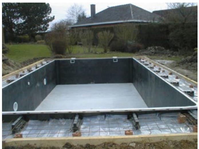
4.8 Positioning the welded wire mesh:
Steel welded wire mesh, lattice 10 × 10 × 4 (or a double layer of 20 × 20 × 4 ).
Roll the mesh out over the surface of pool base. Ensure that it is not flattened against the floor of the excavation so that it may be correctly imprisoned WITHIN THE CONCRETE when the underslab is poured. Use « L » shaped iron bars to grip the mesh, raise it and position it at about 2/3 the depth of the underslab.
Sections of mesh should overlap by 20 to 30~cm and should be tied together.
NOTE
If fibreglass reinforced concrete is used do not reinforce with a welded wire mesh.
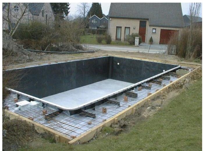
4.9 Pouring the concrete
Pour a slab 10 to 15 cm thick using reinforced concrete, 350 kgs/m3, on land that is stable, not muddy or waterlogged and that is well consolidated. Depending on the surroundings, a concrete mixing truck may be used to pour the underslab. First calculate the volume of concrete required as follows:
Base surface area x 0.10 = Volume in m3 (for a 10cm underslab)
If access is difficult, extension hoses (up to about 30m ) or a concrete pump may be used.
Either lay down:
1 layer, smoothed immediately.
- 2 layers: 1 layer of concrete and subsequently a finishing screed (5 cm thick). When a «LINER» is used for waterproofing the finish of surface must be impeccable. Make sure that the upper surface of the main drain is flush with the finished surface of the underslab.
IMPORTANT
The outer edge of the concrete underslab must not exceed the outer edge of the flanges jutting back from the panels, otherwise it will not possible to drive the anchoring stake against the panel into the support brace.
Therefore, ensure that the shuttering or formwork is at most 10 cm from the line marking the inner pool wall or include a blank to leave a space for each supporting brace. After the PPP panels are installed, round off all the connecting angles and the angles at the base of the panels with mortar using a length of PVC tubing Ø 100 mm.
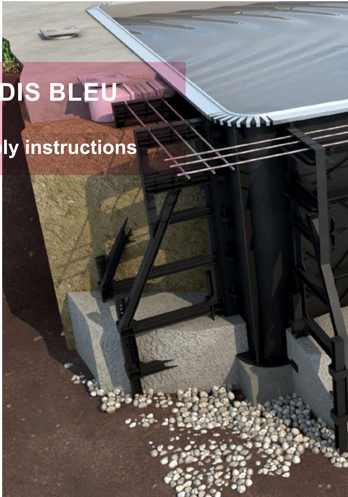
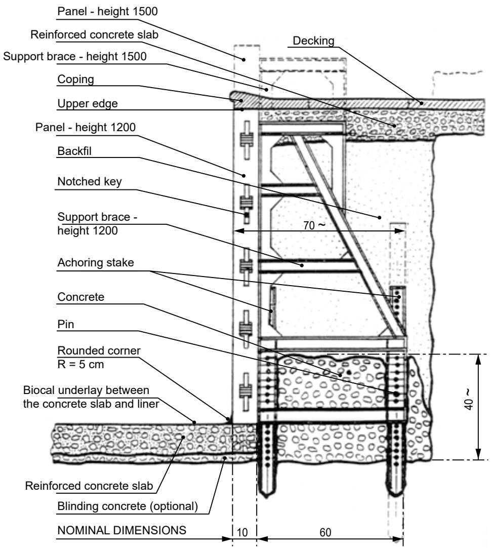
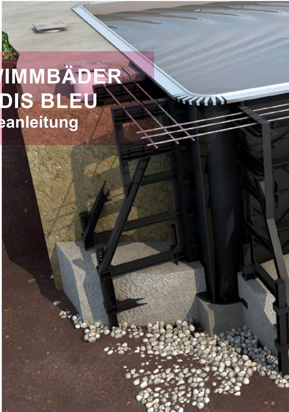
Cross section view of the completed assembly
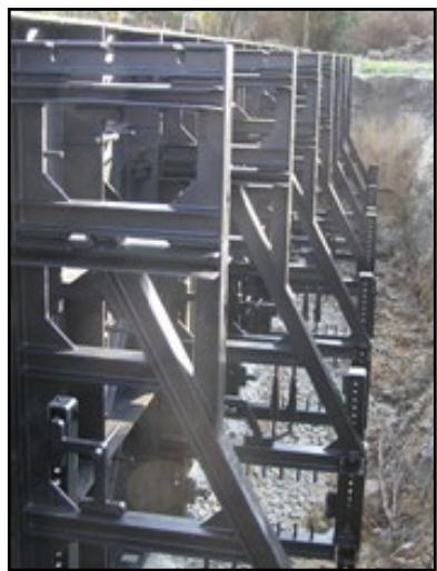
5. ASSEMBLING THE WALLS
It is always best to have a level surface, however, unless the concrete underslab has already been poured, the bottom of most excavations will not be perfectly flat.
The quick positioning PPP supporting braces get around this inconvenience and remove the need for jacks or other levelling systems.
5.1 CORNER PANELS AND SUPPORTING BRACES
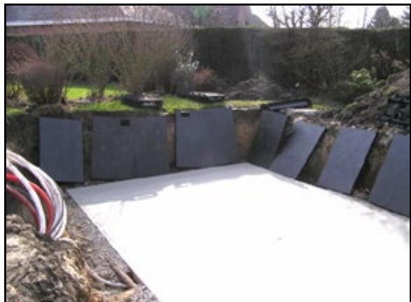
After completing the excavation and preparing the bottom of the excavation, position the PPP panels and corner panels in the hole, leaning them against the sides of the excavation (smooth side facing out).
CAUTION
Ensure that you have the correct number of panels and that the panels featuring cut-outs for the skimmer, water suction and water return fittings and the underwater lights, if any, are correctly positioned. Ensure that the cut-out is oriented upwards.
As far as possible position panels of similar dimensions opposite each other.
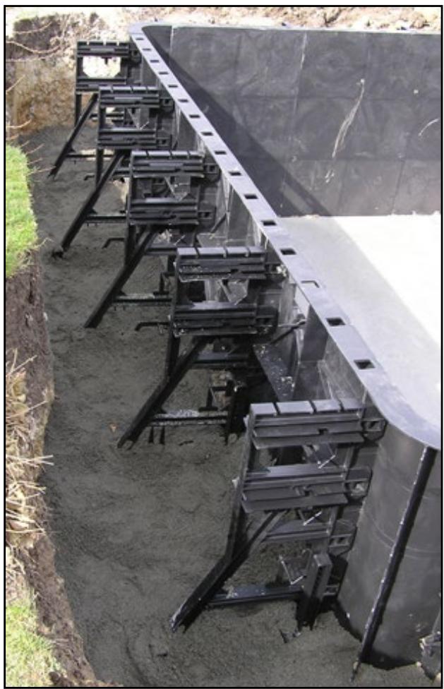
Place the supporting braces all around the pool perimeter close to the panel flanges. These will be used to join the panels together.
No nuts or bolts are required; the correct number of self-locking keys and positioning pins are moulded with each supporting brace and may be easily detached one by one as they are needed.
Depending on the pool wall height selected, 2 pins and 4, 5, or 6 keys will be needed to join 2 panels, or one panel and a corner panel, together with a supporting brace. The only tool required for assembly is a mallet.
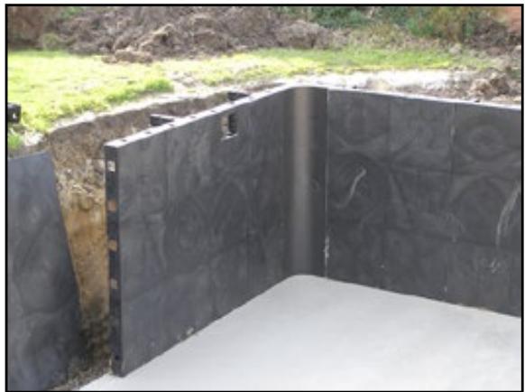
Standing in the work space between the panels and the edge of the excavation, bring together 2 panels, lining up the square apertures in the panel flanges.
Start with the corners. Hold a supporting brace perpendicular to the right hand panel with the centring pins opposite the apertures, push them through from right to left until the holes into which the keys will be inserted are far enough from the inner surface of the flange on the left hand panel.
Position the keys so that their vertical edge is parallel to the panel flange and lock the assembly together using the mallet.
Check that the upper edges of the panels are thus automatically aligned.
Continue systematically in the same way for all Paradis Bleu panels and corner panels checking that these are correctly aligned with the pool perimeter marked out by string tied around the stakes planted in the corners A.B.C.D. or marked in blue on the underslab once this had dried.
Check the base rectangle by measuring the length of the 2 diagonals: these should be equal.
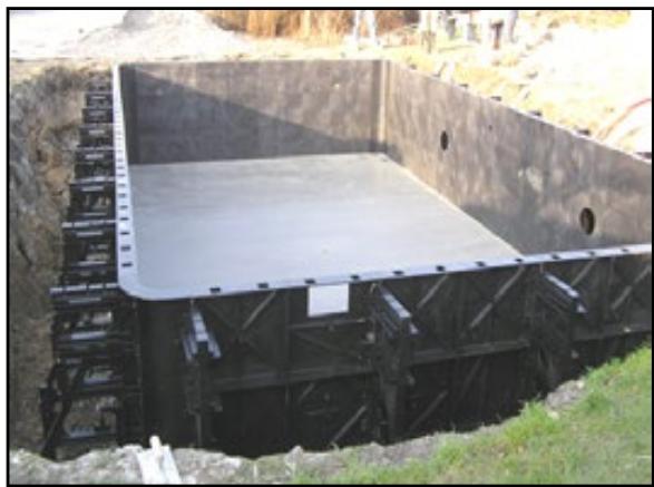
Each supporting brace (height 1.25 m and 1.50 m only), comes with 2 moulded synthetic resin stakes and a positioning pin.
Place the stakes over the apertures provided for this purpose in the supporting brace.
Check one last time that the corresponding Paradis Bleu panel is correctly aligned along the pool perimeter and drive the first stake (that closest to the panel) into the ground using a hammer. Drive in the second take.
Stakes secure the pool wall to the ground, they may also be used to level the upper edges of the panels and correct their vertical position.
To do this, simply slide the supporting brace along the rear stake and push in the positioning pin when the desired position is attained.
Continue around the pool using a spirit level to ensure that the panels are vertical and that the upper edges are horizontal at each supporting brace.
1.00 m supporting braces are fastened to the ground by a 10 x 10 belt of steel reinforcement bars or 'rebars' onto which concrete is poured. Cut the steel belt to pass it through the supporting brace and reattach by tying with steel reinforcement bars
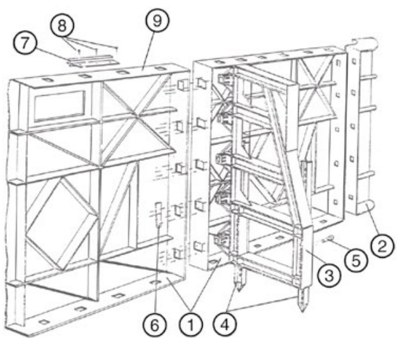
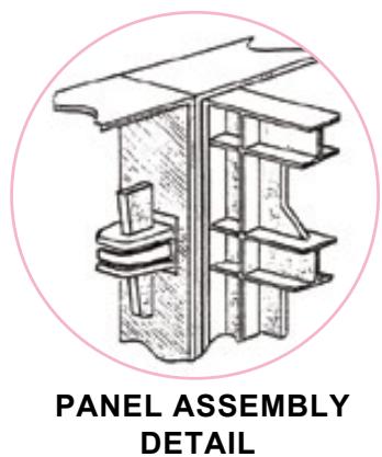
1 - Panel
2 - Corner
3 - Supporting brace
4 - Adjustable stakes (1.25 m and 1.50 m)
5 - Positioning pins
6 - Locking key
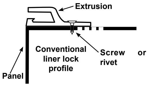
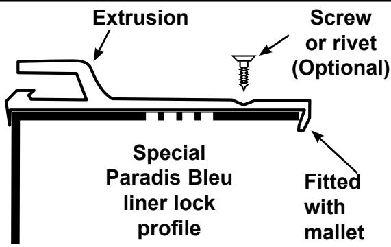
7 - Liner lock profile
8 - Self tapping screws or rivets (not provided)
9 - Upper edge of the panel
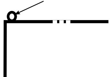
Before the liner may be fitted to the Paradis Bleu pool, a female extruded profile (the liner track) must be fitted to the top of the panel to accept the male extrusion or bead welded to the edge of the liner. The liner lock track comes in 2m long straight strips and 4 corner pieces provided with the kit. Begin installation of the track with the 4 corners. Screw these into position using self tapping screws or rivets after piercing a corresponding hole in the upper edge of the panel. Next, install the straight strips between the corners fixing in them in position with self tapping screws or rivets every 20 to 25~cm . The track should be flush with the front surface of the panel on the pool side. The seams between the strips should not coincide with the seams between the panels.
Note: Panel positioning should be completed before the track is installed. However if, during track installation, it is found that positioning is not quite perfect, remove the self locking key from a supporting brace and slide a lever under the panel to perform the slight manipulations necessary.
Silicon bead, approx 4 mm
CAUTION
Once the panels have been assembled with their supporting braces, the liner track has been installed and all readjustments have been completed, block the assembly in position by pouring mortar behind the panels. Take care to ensure that the supporting braces are encased. The purpose is to increase the strength and stiffness of the panels and prevent infiltration during heavy rain.
Some panels are precut to receive proswell panel pool fittings that come with the necessary prefix screws and spacers
7.1 Installation of the various items
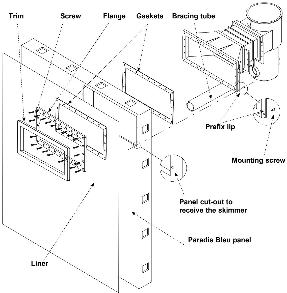
7.1.1 WM Skimmer
- Position the skimmer in the cut-out. The skimmer mouth should fit into the panel flush with its inner surface.
- Next, screw the countersunk prefix screws through the skimmer lip, use washers.
- The skimmer should be braced in position using the PVC tube diam. 63 provided with the skimmer, bearing on one side against the indent provided for this purpose on the skimmer body, and, on the other side, on the rear surface of the panel.
This installation technique is preferable to any other because the liner is sandwiched between two gaskets thus almost eliminating the risk of leaks.
Before mounting the skimmer, cut the pin on top of the supporting brace.
Installing the Skimmer WM-Long code 40261029
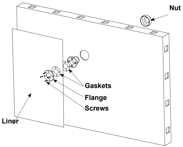
7.1.2 Water return and vacuum point
- Using a hole saw, code 30309010, create a hole in the panel at the desired position.
- From the front surface, fix the return fitting into the panel. Screw and tighten the nut behind the panel.
Installing return fittings and vaccum point
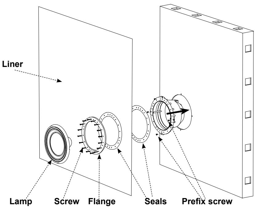
7.1.3 Fixed underwater light
From the front of the panel (the inner pool side) fix the niche into the cutout. The screw housings fit into the 12 mm pre-drilled holes. Insert a self tapping countersunk screw in each of the 4 small notches provided and, using washers, tighten to secure the niche in position.
Installing the underwater light
8.1 Preparation
Before installing the liner, check that there are no foreign bodies in the pool structure that could damage it. The finish of the underslab will determine the final look of the pool.
Concrete underslabs must be scrupulously clean. Each square centimetre must be vacuumed using an industrial machine. Bumps should be smoothed and any cracks should be filled in using fine cement.
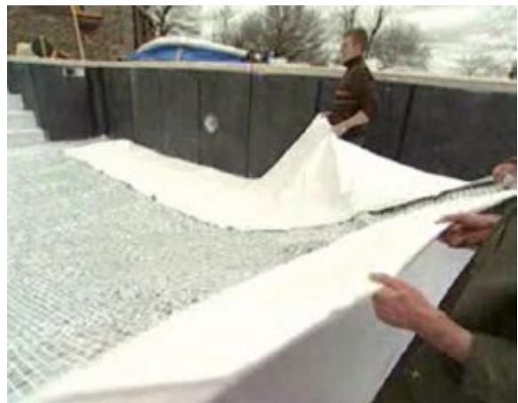
NOTE:
- Fit the woven PE underlay on the floor of the pool.
- This underlay is essential and absolutely must be fitted.
CAUTION
To keep the underlay in position, use the adhesive strips provided (the purpose of the adhesive tape is to mask the joins between panels) to stick the underlay to some panels.
Do not use any adhesive tape other than that provided. Prolonged contact between the liner and other types of tape could result in the migration of tape components into the PVC liner causing stains.
Liner installation is more straight-forward when it is hot and sunny (at least 18^ ) early in the afternoon. Creases are easier to smooth out and the liner is more supple. If the weather conditions are not suitable, leave the liner in its packaging in a heated room for one or two days before installing it. During the winter, the liner should be fitted under the protection of a heated shelter.
Installation requires 3 or 4 people depending on the pool dimensions.
8.2 Fitting
Unwrap the liner in the shallow end. Obviously the installers should remove their shoes.
With one person positioned at either width edge, two other people in the pool take a hold of the other two corners of the liner and unfold it lengthways over the surface of the pool.
With one person positioned at either width edge, two other people in the pool take a hold of the other two corners of the liner and unfold it lengthways over the surface of the pool.
Position one corner of the deep end, snap it into the track and hold it in position either using the locking trim half a wooden clothes peg (remove the metal spring from the clothes peg to split it into two halves).
Snap the liner into the track along the width to the other corner of the deep end, position it correctly and hold it in position with wooden clothes pegs (stretch the liner if necessary).
Proceed down the lengths of the pool towards the shallow end. It may be necessary to hold the liner in position using half pegs.
Caution: if the liner needs to be slid laterally, detach it rather than sliding it along the rail to avoid any risk of tearing at the liner track joins.
Next position the liner, pulling so that the base fits perfectly to the base of the pool. For pools with a flat base, the welded seam of the liner may be lined up along the angle formed between the base of the pool and the bottom of the pool wall.
Once the liner is correctly positioned and snapped into the liner track, insert the vacuum pump to remove the air between the walls and the liner and flatten the liner against the pool walls and base before filling the pool with water:
- Detach a section of the liner (30 to 40~cm ) around the midpoint of a wall
- Slide the tube of a vacuum pump between the liner and the pool wall. Block the liner in position on either side of the tube using halves of wooden clothes pegs.
- Seal off the area around the tube or nozzle and any other section where air could be drawn in between the liner and the pool wall (skimmer covers, pool fittings, filtration system pipes, panel seams, etc.).
- Switch on the vacuum pump. An industrial vacuum cleaner or professional vacuum pump such as QVAC is recommended. A household vacuum cleaner, even with the bag removed, would be a lot less efficient. After a period of time (varies with the strength of the vacuum pump) the liner is flattened against the walls of the pool and takes on its shape. Final positioning in the corners will only be achieved with the pressure exerted by the water.
- Check that the liner is correctly positioned in the pool.
IMPORTANT
Leave the vacuum pump running while filling the pool. Should it be necessary to stop the vacuum pump, for whatever reason, stop filling the pool. Restart filling once the vacuum pump is switched back on and the liner is flattened against the pool wall.
9. LINES AND PIPEWORK
All the pool fittings should be connected to the pool machine room by means of buried pipes.
Use good quality PVC or Polyethylene pipe approved for installations subject to freezing and high pressure (6 to 8 bar).
Before backfilling, connect pipes to the return fittings and skimmers. To avoid the formation of airlocks within the lines, the suction and return lines should be laid on a slightly sloping bed of sand.
Similarly, to avoid damage during backfilling, rigid PVC or polyethylene pipes leading to the machine room should not be laid horizontally out from the skimmer or return fitting, but should be laid directly vertical down to the bottom of the excavation. Once they reach a stable surface they can be laid horizontally on a bed of sand.
The suction and return lines should follow a constant even slope between the filter and the pool. This will facilitate drainage of the lines in winter. To install a plastic union: wind Teflon tape around the threading and then screw into the corresponding opening.
10. FILLING
This operation must be carried out quickly and simultaneously with backfilling of the space behind the walls of the pool (refer to the following section «BACKFILLING»). The water flow-rate must be sufficiently high. If possible use several hoses together.
After the liner has been positioned, start to fill the diving pit with the vacuum pump switched on. If using a garden hose, first add several litres of water to the bottom of the diving pit and leave the end of the hose submerged.
Once the water depth reaches 10 above the main drain, cut-out the liner around this fitting (refer to the instructions provided below).
Then, without stopping the vacuum pump, continue to fill the pool while gradually backfilling as the water level reaches the bottom of the underwater light, then the return fittings and lastly the skimmers. Position the outer gaskets and flanges and cut-out the liner as described further on in the section entitled « Cutting out the pool fittings »
11. CUTTING OUT THE POOL FITTINGS
When the water level is about five centimetres under each of the following fittings:
- underwater lights,
- vacuum points,
return fittings - skimmers
(refer to the paragraph entitled « FILLING »), the gaskets and flanges should be mounted on and secured to the liner. To do this, press on the liner to locate the areas corresponding to the screw holes and cut using a sharp implement.
Next, place the gasket against the liner with the flange over it. Thread the screws through and tighten them, locking the flange in position, check that the gasket is centred.
Once all attachment items are locked in position, cut out the portion of liner obstructing the opening using a sharp knife.
IMPORTANT
Gaskets ensure waterproofing, therefore check that they are in good condition when they are installed.
To avoid damaging them when cutting out the liner, follow these recommendations;
- First cut out an opening in the liner smaller than the nominal diameter.
- Then rectify the contour using a sharp knife or cutter staying flush with, but not cutting into, the sealing gaskets.
- For the main drain, remove the protective adhesive from the screw holes before positioning the gasket.
The underwater lights each comes with a cable approximately 2 meters long. Alength of cable (approximately 1 meter) should be left coiled in the niche to allow the underwater light to be removed from its niche for maintenance, for example to change a bulb, without partially emptying the pool.
12. BACKFILLING
For flat base pools, start backfilling and filling with water simultaneously.
For pools with a diving pit, start backfilling as soon as the water level reaches the bottom of the panels, that is, once the diving pit has been filled with water.
The initial bottom layer around the pool should be of some porous material (sand gravel) to provide efficient drainage away from the pool walls. Sand should be used in this layer.
Backfill should contain as little clay as possible. Backfilling should be carried out in successive layers 15 to 20~cm deep as the water level in the pool rises such that the pressure exerted by the water is cancelled out by the pressure exerted by the earth.
As the successive layers of backfill are laid down, these should be tamped down either by walking on them or using a rammer. The backfill may be slightly dampened before hand or may be wetted while it is being shoulled into the excavation. Damping or wetting improves the tamping and is recommended if a deck is to be built soon after the installation of the pool.
To prevent breaks in the deck caused by the settling of the backfill over time, lay the deck on pillars (concrete blocks laid head to head) or piles spaced at intervals of 2.50m around the periphery. The pillars or piles are built before backfilling is started. The deck concrete slab should be 'cut' every 3m before the concrete cures.
However, we recommend that you wait several months after the pool has been filled before installing the deck. This is the time necessary to allow settling of the backfill.
13. UPPER RING BEAM
A reinforced concrete upper ring beam should be laid immediately to stabilise and reinforce the pool structure and to allow the coping to be laid.
Slide reinforcing steel bars through the upper holes in the supporting braces provided for this purpose (3 or 4 reinforcing bars depending on the panel height).
At the skimmers, pass the rebars over or under the fitting to ensure the continuity of the beam. The vertical edge of the supporting brace can be used to prop the formwork.
Pour the concrete ring beam, depth 20 cm, 350 kgs/m3. Concrete should be poured in one go with no rework.
Coping may be laid on a thin layer of screed or on special cement.
SCHWIMMBÄDER PARADIS BLEU
Montageanleitung
MONTAGEANLEITUNG
$$ A D = B C, D 1 = D 2 \text {u n d} D C = A B $$