USER MANUAL LX-M-2000 LEXMAN
Electrical products must not disposed of out with domestic waste. They must be taken to a communal collecting point for environmentally friendly disposal in accordance with local regulations. Contact your local authorities or stockist for advice on recycling. The packaging material is recyclable. Dispose of the packaging in an environmentally friendly manner and make it available for the recyclable material collection-service.
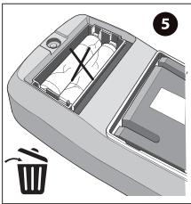
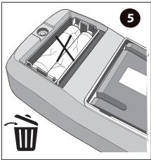
Don't throw batteries or out of order products with the household waste (garbage). The dangerous substances that they are likely to include may harm health or the environment. Make your retailer take back these products or use the selective collect of garbage proposed by your city.

ADEO Services -
135 Rue Sadi Carnot - CS 00001
59790 RONCHIN - France

5 GUARANTEE YEARS\*
EAN CODE : 3276007463705

FR Multimètre numérique
calibrage automatique LX-M-2000.
Manuel d'utilisation.
Multímetro digital calibrado
automático LX-M-2000.
Manual de utilización.
PT Multímetro digital de
calibração automática
LX-M-2000.
Manual de utilização.
IT Multimetro digitale auto-ranging LX-M-2000.
Manuale per l'uso.
Ψηφιακό πολύμετρο
αυτόματη βαθμονόμηση
LX-M-2000.
Εγχειρίδιο χρήσης.
Multimetr cyfrowy automaty-
czna kalibracja LX-M-2000.
Instrukcja obsługi.
Цифровий мультиметр з
автоматичним
калібруванням LX-M-2000.
Керівництво з експлуатації.
LO LX-M-2000 Multimetru digital
cu calibrare automată.
Manual de utilizare.
Auto-calibration digital
Multimeter LX-M-2000.
User guide.
Translated from original instructions.
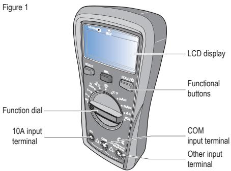
Présentation

natural_image
Diagram of a trash bin with an open drawer and a trash can, no text or symbols present
natural_image
Line drawing of a car rearrest door with battery compartment (no text or symbols)
natural_image
Mechanical component diagram showing a screwdriver inserted into a tray with an arrow indicating rotation (no text or symbols)
natural_image
3D rendering of a car head panel with a directional arrow indicating rotation (no text or symbols)
natural_image
3D rendering of two metallic pipe fittings connected at a junction point (no text or symbols)
natural_image
Illustration of three different types of electrical probes with a curved arrow indicating rotation (no text or symbols present)

Introducción
natural_image
3D diagram of a plastic tray with internal compartments and a labeled waste bin (no text or symbols)
natural_image
Line drawing of a car rearrest door with battery compartment and side compartments (no text or symbols)
ES
natural_image
Illustration of a screwdriver pressing down on a device (no text or symbols visible)

natural_image
3D rendering of a car head panel with a curved arrow indicating rotation (no text or symbols)
natural_image
3D rendering of two metallic pipe fittings connected to a central cylindrical component (no text or symbols)
natural_image
Illustration of soldering tools including a pen, screwdriver, and terminal block (no text or symbols)
Introdução
| Alcance | Resolução | Precisão |
| 9.999nF | 0.001nF | Mode REL : ±(4%+10) |
| 99.99nF | 0.01nF | ±(4%+5) |
| 999.9nF | 0.1nF | ±(4%+5) |
| 9.999μF | 0.001μF | ±(4%+5) |
| 99.99μF | 0.01μF | ±(4%+5) |
| 999.9μF | 0.1μF | ±(4%+5) |
| 9.999MF | 0.001MF | ± 10% |

natural_image
3D rendering of a trash bin with an open lid and internal compartments, no text or symbols visible
natural_image
Line drawing of a car interior showing battery pack and door panel (no text or symbols)
PT
natural_image
Diagram of a screwdriver pressing down on a mechanical component with an arrow indicating rotation (no text or symbols present)
natural_image
3D rendering of a car head panel with a curved arrow indicating rotation (no text or symbols)
natural_image
3D rendering of two metallic pipe fittings connected at a V-shaped junction (no text or symbols)
natural_image
Illustration of three different types of electrical probes with a curved arrow indicating motion (no text or symbols present)

natural_image
Illustration of a cable being inserted into a socket (no text or symbols)
Introduzione
natural_image
3D diagram of a car interior showing internal compartments and a trash bin (no text or symbols)
natural_image
Diagram of a car rearview battery pack with two cylindrical components (no text or symbols)
IT
Specifiche generali
natural_image
Diagram of a medical device with a pipette inserted, showing a step and arrow indicating motion (no text or symbols present)
natural_image
3D rendering of a car interior frame with a curved arrow indicating rotation (no text or symbols)
natural_image
3D rendering of two metallic pipe fittings connected at a V-shaped junction (no text or symbols)
natural_image
Illustration of three different types of electrical probes with a curved arrow indicating rotation (no text or symbols present)
natural_image
Illustration of a cable being inserted into a socket (no text or symbols)
Εισαγωγή
natural_image
Interior view of a car recycling bin with a hand pointing to the lid (no text or symbols visible)
natural_image
Line drawing of a car rearrest door with battery compartment (no text or symbols)
natural_image
Mechanical component diagram showing a needle inserted into a base with an arrow indicating rotation (no text or symbols)
natural_image
3D rendering of a car head panel with a curved arrow indicating rotation (no text or symbols)
natural_image
3D rendering of two metallic pipe fittings connected at a V-shaped junction (no text or symbols)
Οδηγίες χρήσης

Προσοχή:
natural_image
Illustration of three different types of electrical probes with a curved arrow indicating motion (no text or symbols present)

natural_image
Simple line drawing of a plug inserted into a socket (no text or symbols)
Wstep
natural_image
Interior view of a car recycling bin with a labeled waste bin (no text or symbols on the diagram itself)
natural_image
Line drawing of a car rearview compartment showing battery and door mechanism (no text or symbols)
natural_image
Diagram of a pipette dispensing liquid into a device with an arrow indicating motion (no text or symbols present)
natural_image
3D rendering of a car head panel with a curved arrow indicating rotation (no text or symbols)
natural_image
3D rendering of two metallic pipe fittings connected at a junction point (no text or symbols)
Instrukcje obsługi

Ostrzeżenie :
natural_image
Illustration of three different types of electrical probes with arrows indicating motion (no text or symbols)
natural_image
Illustration of a medical or electrical device with a metallic tool inserted into a rectangular socket (no text or symbols visible)
Вступ
natural_image
3D diagram of a car interior showing internal compartments and a labeled trash bin (no text or symbols present)
natural_image
Diagram of a car rearrest door showing battery and housing components (no text or symbols)
UA
natural_image
Diagram of a pipette dispensing liquid into a device with an arrow indicating motion (no text or symbols present)

natural_image
3D rendering of a car head panel with a curved arrow indicating rotation (no text or symbols)
natural_image
3D rendering of two metallic pipe fittings connected at a junction point (no text or symbols)
natural_image
Illustration of three different types of electrical probes with one being shifted (no text or symbols present)
natural_image
Simple line drawing of a plug inserted into a socket (no text or symbols)
Introducere
natural_image
Interior view of a car recycling bin with a trash bin and a numbered label (5), no text or symbols present.
natural_image
Line drawing of a car rearrest door showing battery compartment and side panel (no text or symbols)
RO
natural_image
Diagram of a medical device with a pipette inserted, showing a step and arrow indicating motion (no text or symbols present)

natural_image
3D rendering of a car head panel with a curved arrow indicating rotation (no text or symbols)
natural_image
3D rendering of two metallic pipe fittings connected at a junction point (no text or symbols)
natural_image
Illustration of three different types of electrical probes with a curved arrow indicating rotation (no text or symbols present)
natural_image
Illustration of a plug inserted into a socket with wires (no text or symbols)
Introduction
LX-M-2000 is a palm sized multimeter with automatic calibration. This CE certified multimeter is CAT III 600V which can withstand 6000kV surge voltage. The LX-M-2000 is designed with high voltage warning and over range alarm, making this series great for a wide range of measurement needs.
Features
● Smart appearance with comfy handle.
● Pass 2-meter drop test.
● Large LCD screen with 6000 counts display, true RMS measurement, fast ADC digital converter (3 times/s).
● Overload protection with alert.
- Extensive range for capacitance measurement, short response time. E.g. When measuring ≤slant 10mF , response time ≤slant 6s .
● Support NCV, frequency (LX-M-2000).
● Support up to 600V/10A AC/DC current and voltage measurement.
● Backlight installed for dim occasions.
- Energy saving.
Open box inspection
Open the package box and take out of the device. Please check whether the following items are deficient or damaged and contact your supplier immediately if they are.
- User manual .... 1 pc
● Test leads 1 pc
● K-type thermocouple ..... 1 pc
Safety instructions
Safety standards
● CE, EN 61326-1 : 2021; EN 61326-2-2: 2021
EN 61010-1:2010/A1 : 2019 ; EN IEC 61010-2-033; 2021/A11:2021
CAT III 600V, double insulation standard, over voltage standard, over voltage standard, and RoHS, pollution grade II.
Safety instructions
1 - Do not use the device if the rear vovered up or it will pose a shock hazard.
2 - Do not use the device if the device or test leads appear damaged or if you suspect that the device is not operating properly. Pay particular attention to the insulation layers.
3 - During measurement, keep your fingers behind the finger guard.
4 - Do not input over 600V voltage between the device and the grounding.
5 - Use caution to measure voltage > DC 60V or AC 30Vms.
6 - Never input voltage and current exceeding yhe value listed on the device.
7 - Functional dial should be switched to proper position.
8 - Do not switch the functional dial during measuring.
9 - Do not change the internal circuit of the device in order to avoid the damage to the device a,d users.
EN
10 - Replace the fuse with the specified model
11-To avoid false reading, replace the battery when the battery indicator
appears.
12 - Do not use or store the device in high temperature, high humidity, flammable, explosive or strong magnetic field environments.
13 - Use damp cloth to clean the case; do not use detergent containing solvents or abradants.
14 -Before each use verify meter operation by measuring a known voltage or current. If the equipment is used in a manner not specified by the manufacturer, the protection provided by the equipment may be impaired.
Symbols
| Symbol | Description |
| Low battery |
| Caution, possibility of electric shock |
| Alternating current |
| Direct current |
| Double insulation |
| Grounding |
| Warning |
| CE | Comply with European Union Standards |
| CAT III | It is applicable to test and measuring circuits connected to the distribution part of the building's low-coltage MAINS installation |
General specifications
1 - Max voltage between input terminal and earth grounding : 600Vrms.
2 - Fuse tye :
10A Jack : F 10A H 600V Fuse Φ 6x25mm (or Φ6x32mm).
mA/μA Jack : F 600mA H 600V Fuse Φ6x32mm.
3 - Display count : 6000
overload indication : OL, refresh 3 times/s.
Others :
1 - Range : Auto
2 - Backlight : Manual, shutdown after 30s.
3 - Polarity : - for negative pole
4 - Data hold indication : H
5 - Low power indication : □
6 - Operating temperature : 0°C \~40°C (32°F \~104°F)
Storage temperature : -10°C \~ 50°C (14°F \~ 122°F)
Relative humidity : ≤75% at 0°C\~30°C; ≤50% at 30°C\~40°C.
7 - Operating altitude : 0 \~2000m
8 - Battery type : AAA 1.5Vx2
Dimension : 155mmx76.5mmx49mm
9 - Weight 255g (with batteries)
10 - Electromagnetic compatibility :
RF ≤ 1V/m, overall accuracy = specified accuracy + 5% of range
* .SELECT : cycle switch the functions through AC/DC mV range, frequency, resistance/diode/continuity, °C/°F.
* .REL : the voltage, current and capacitance mode, press this button to remove the base.
* .HOLD/LIGHT : press the button once to hold the reading. Press third button for 2 seconds to turn on/off the backlight.
Operation instructions
To avoid false reading, replace the battery if the battery low power symbol □ appears.
Also pay special attention to the warning sign △ besides the test lead housing, indicating that the tested voltage or current must not exceed the value listed on the device.
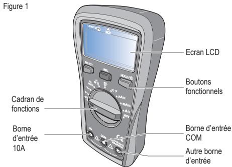
- AC/DC voltage measurement (see figure 2)
1 - Switch the dial to ACV position
2 - Insert the red test lead to VΩ mA jack, black to COM jack.
3 - Connect test leads with the load in parallel.
4 - At mV position, press SELECT to enter frequency measurement (10Hz \~ 1MHz)
5 - Reading is displayed.

Warning :
- Do not input voltage over 600Vrms, or it may pose shock hazard
● Be cautious when measuring high voltage
EN

Note :
- Before using the device, if the voltage is unknown, switch the dial to the maximum range position and reduce the range according to the practical reading.
● Test a known voltage to verify the device.
- When input impedance about 10M Ω, there may be errors when measurement high voltage. Input impedance ≤10kΩ, measurement errors can be ignored (≤0.1%).
Figure 2
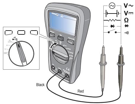
- Resistance measurement
1 - Switch the dial to resistance position.
2 - Insert the red test lead to VΩ mA jack, black to COM jack.
3 - Connect test leads with the load in parallel.
4 - Reading is displayed.

Note :
1 - Switch the dial to continuity position
2 - Insert the red test lead to VΩ mA jack, black to COM jack.
3 - Connect test leads with the load in parallel.
4 - Reading is displayed. Measurement resistance < 51 circuit is open status. Measurement resistance ≤ 10 , circuit is in good conduction status, buzzer will go off.

Warnings :
Switch off the power supply to the circuit, and fully discharge all capacitors.
- Diode measurement (see figure 2)
1 - Switch the dial to diode position.
2 - Insert the red test lead to VΩ mA jack, black to COM jack.
3 - Red test lead to positive pole, black to negative pole.
4 - Reading is displayed.
«OL» symbol appears when the diode is open polarity is reserved. For silicon PN junction, normal value : 500 \~ 800mV (0.5 \~ 0.8).

Notes :
Switch off the power supply to the circuit, and fully discharge all capacitors. Voltage for testing diode is about 4.0V/1.5mA.
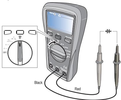
- Capacitance measurement (see figure 3)
1 - Switch the dial to capacitance measurement.
2 - Insert the red test lead to V Ω mA jack, black to COM jack.
3 - Red test lead to positive pole, black to negative pole.

Notes :
- Switch off the power supply to the circuit, and fully discharge all capacitors.
- Before measuring capacitors (especially for high voltage capacitors), please fully discharge them.
- If the tested capacitors is shorted or its capacity is over the specified range «OL» symbol will be displayed on the screen.
- When measuring large capacitors, it may take a few seconds to obtain steady readings.
- When there is no input, the device displays a fixed value (intrinsic capacitance).
- For small capacitance measurement, to ensure measurement accuracy, the measured value must be subtracted from intrinsic capacitance. Or users can measure small capacity capacitors with relative measurement function (REL) (the device will automatically subtrack the intrinsic capacitance).
Figure 3
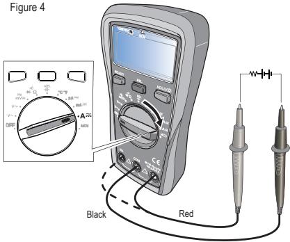
- AC/DC current measurement
1 - Switch the dial to AC/DC current position.
EN
2 - According to the current being measured. Insert the red test lead to VΩmA jack or 10A jack, black to COM jack.
3 - Connect test leads with the circuit in series.
4 - Reading is displayed.

Notes :
● Before measuring, switch off the power supply of the circuit.
- If the range of the measured current is unknown, select the maximum range and then accordingly reduce.
- There are fuses inside VΩmA jack and jack. Do not connect the test leads with any circuits in parallel.
- If the tested current is about 10A, each measurement time is about 10 seconds (less than 30s) and the next test should be after 15 minutes
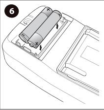
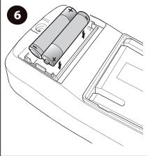
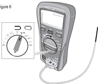
- Temperature measurement
1 - Switch the dial to battery position.
2 - insert K-type thermocouple to the device and place the test probes on the object under measurement.
3 - Reading is displayed

Note :
● Only K-type thermocouple is applicable.
● The measured temperature should be less than 250^ C/482°F ( ^ F = ^ C* 1.8+32).
- Turn on the device, after «OL» symbol appears, insert K-thermocouple into the device.
Figure 6
8. NCV
1 - Switch the dial to NCV position.
2 - Place the device near the measured object. «-»symbol indicates the intensity of the electric field. More «---» and the higher the buzzer frequency, the higher the electric field intensity.
Figure 7
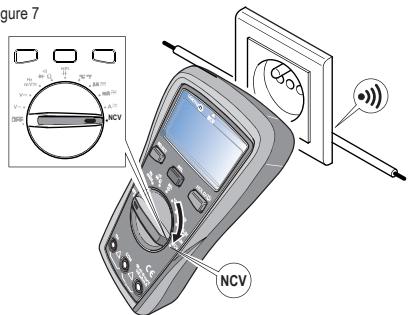
3 - Intensity of electric field.
* « EF » : 0\~50mV
* "-":50-100mV
* "-":100-150mV
* "—":150-200mV
* "—": > 200mV


Accuracy: ± (% of reading + numerical value in least significant digit slot), 1 year warranty.
Ambient temperature : 23^ C + 5^ C (73.4F ± 9^ F).
Ambient humidity : ≤ 75% RH

Note :
To ensure accuracy, operating temperature should be within 18^ C - 28^ C.
Temperature coefficient - 0.1* (specified accuracy)/°C (< 18°C or >28°C)
1. DC voltage
| Range | Résolution | Accuracy |
| Position |
| 600.0mV | 0.1mV | ±(0.7%+3) |
| 6.000V/6000mV | 0.001V/1mV | ±(0.5%+2) |
| 60.00V | 0.01V | ±(0.8%+1) |
| 600.0V | 0.1V | ±(0.7%+3) |

Input impedance : About 10M Ω
Results might be unstable at mV range when no load is connected. the value becomes stable once the load is connected. Least significant digit ≤±3 .
Max input voltage : ± 600V, when the voltage ≥ 610V, «OL» symbol appears and the buzzer goes off.
Overload protection : 600Vrms (AC/DC).
EN
2. AC voltage
| Range | Résolution | Accuracy |
| Position |
| 600.0mV | 0.1mV | ±(1.0%+2) |
| 6.000V | 0.001V/1mV | ±(0.7%+3) |
| 60.00V | 0.01V | ±(1.0%+2) |
| 600.0V | 0.1V | ±(1.2%+3) |
| 10Hz ~ 1MHz | 0.01VHz/0.001MHz | ±(0.1%+5) |

Input impedance : About 10MΩ
Display sine wave true RMS. Frequency response : 40Hz \~400Hz.
Max input voltage : 600Vrms. when the voltage ≥ 610V, «OL» symbol appears and the buzzer goes off
Overload protection : 600Vrms (AC/DC)
Frequency sensitivity about 300mV.
3. Resistance measurement
| Range | Résolution | Accuracy |
| Position |
| 600.0Ω | 0.1Ω | ±(1.0%+2) |
| 6.000kΩ/6000Ω | 0.1kΩ/1Ω | ±(0.8%+2) |
| 60.00kΩ | 0.01kΩ | ±(0.8%+2) |
| 600.0kΩ | 0.1kΩ | ±(0.8%+2) |
| 60.00MΩ | 0.01MΩ | ±(2.0%+5) |

Measurement result = reading of resistor - reading of shorted test leads overload protection : 600Vrms.
4. Continuité, Diode
| Position | Résolution | Remark |
| ••• | 0.1Ω | Set valueOpen circuit : resistance >50Ω, no beep.Well-connected circuit : resistance ≤ 10Ωcontinuous beeps. |
| 0.001V | Open circuit voltage : 4V, test current: about 1.5mAOpen circuit voltage : 2.1V, test current: about 1mA.Silicon PN junction voltage : 0.5 -0.8V. |

Overload protection: 600Vrms.
5. Capacitance
| RAnge | Résolution | Accuracy |
| 9.999nF | 0.001nF | Mode REL : ±(4%+10) |
| 99.99nF | 0.01nF | ±(4%+5) |
| 999.9nF | 0.1nF | ±(4%+5) |
| 9.999μF | 0.001μF | ±(4%+5) |
| 99.99μF | 0.01μF | ±(4%+5) |
| 999.9μF | 0.1μF | ±(4%+5) |
| 9.999MF | 0.001MF | ±10% |

Overload protection : 600V-PTC
Test capacitance ≤slant 200nF, adapt REL mode.
6. Temperature
| Range | Resolution | Accuracy |
| °C | -40~1000°C | -40~40° | 1°C | ±4% °C |
| -40~500°C | ±(1.0%+4) |
| >500~1000°C | ±(2.0%+4) |
| °F | -40~1832°F | -40~104°F | 1°F | ±5% °F |
| >104~932°F | ±(1.5%+5) |
| >932~1832°F | ±(2.5%+5) |

Overload protection : 600V.
K-Type thermocouple is o,ly applicable for temperature less than 250^ C/482°F.
7. DC Current
| Range | Resolution | Accuracy |
| Position |
| 600.0μA | 0.1μA | ±(1.0%+3) |
| 6000μA | 1μA | ±(1.0%+3) |
| 60.00mA | 0.01mA | ±(1.0%+3) |
| 600.0mA | 0.1mA | ±(1.0%+3) |
| 6A | 0.001A | ±(1.2%+5) |
| 10.00A | 0.01A | ±(1.2%+5) |

Overload protection : 600Vrms.
μA mA range : F1 Fuse Φ 6x32mm F 600mA H 600V.
10A range : F2 Fuse Φ6x25mm (or Φ6x32mm) F 10A H 600V.
Input current ≥slant 10A, buzzer goes off; input current >10.10A «OL» symbol appears.
8. AC Current
| Range | Resolution | Accuracy |
| Position |
| 600.0μA | 0.1μA | ±(1.2%+3) |
| 6000μA | 1μA |
| 60.00mA | 0.01mA |
| 600.0mA | 0.1mA |
| 6A | 0.001A | ±(1.5%+5) |
| 10.00A | 0.01A |
Frequency response : 40\~400Hz.
Display : true RMS.
Accuracy guarantee range : 5-100% of the range, shorted circuit allows least significant digit ≤2.
Input current ≥slant 10A, buzzer goes off; input current >10.10A «OL» symbol appears.

Overload protection : (similar to DC current).
EN
9. Maintenance

Warnings :
To avoid electric shock, make sure the probes are disconnected from the measured circuit before removing the rear cover.
Make sure the rear cover is tightly screwed before using the instrument.
1. General maintenance
1 - Clean the case with a damp cloth and detergent. Do not use abradants or solvents.
2 - If there is any malfunction, stop using the device and send it to maintenance.
3- The maintenance and service must be implemented by qualified professionals or designated departments.
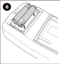
2. Replacements
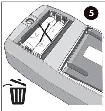
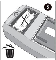
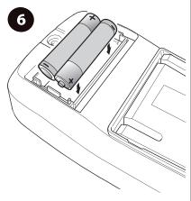
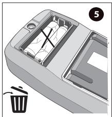
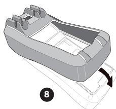
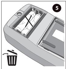
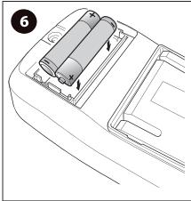
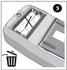
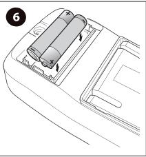
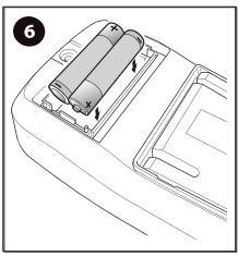
Battery replacement :
The avoid false reading, replace the battery when the battery indicator appears.
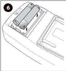
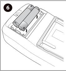
Battery specification : AAA 1.5V x 2.
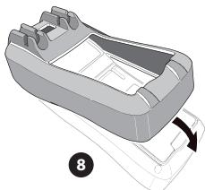
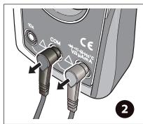
1 - Switch the dial to «OFF» position and remove the test leads from the input terminal.
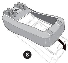
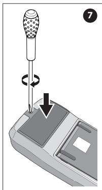
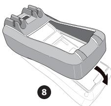
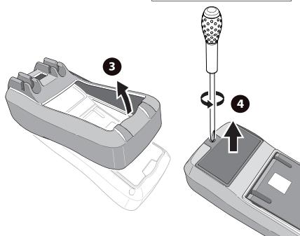
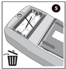
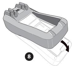
2 - Take off the protective case. Loosen the screw on battery cover; remove the cover to replace the batterie. Please identify the positive and negative pole.
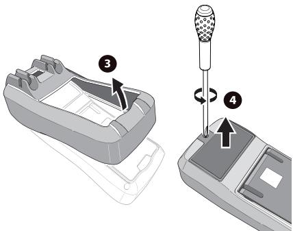
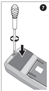
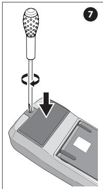
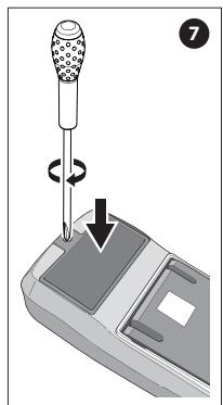
Fuse replacement (this replacement must be done by a professional worker):
1 - Switch the dial to «OFF» position and remove the test leads from the input terminal.
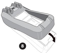
2 - Loosen both screws on the rear cover, and then remove the rear cover to replace the fuse.
Fuse specification :
F1 Fuse Φ 6x32mm F 600mA H 600V.
F2 Fuse Φ 6x25mm (or Φ6x32mm) F 10A H 600V.
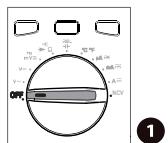
Position OFF
natural_image
3D diagram of a trash bin with internal compartments and a labeled component (no text or symbols)
natural_image
Line drawing of a car interior showing battery compartment and door (no text or symbols)
EN
General specifications
| Model | LX-M-1000-01 |
| AC/DC current | 10A |
| Electrical safety | CAT II 1000VCAT III 1000VCAT IV 600V |
natural_image
Diagram of a mechanical device with a pipette and lever mechanism, showing rotation and movement (no text or symbols)
natural_image
Diagram of a car rear intake manifold with a curved handle and a labeled component (no text or symbols present)
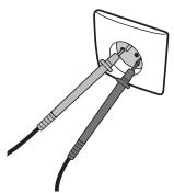
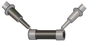
The probe replacement LEXMAN LX-M-1000-01
If insulation on probe is damaged, replace it.

Warnings :
If the test leads need to be replaced, you must use a new one which should meet EN 61010-031 standard, rated CAT III 600V, 10A or better.
About probes
Introduction
The LX-M-1000-01 probes are compatible with the following Lexman products: LX-M-2000, LX-M-1000, LX-M-2100, LX-M-1000-02.
Symbols
| Symbol | Description |
| Warning |
| Double insulation |
| CE | Comply with European Union Standards |
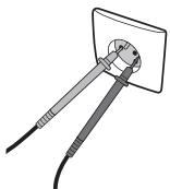
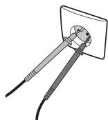
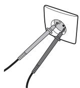
Operating instructions
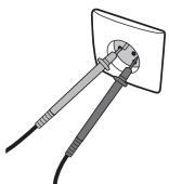
For example, to check the continuity of a fuse, plug the black probe on the COM port and the red probe on the "Ω" port of the multimeter. Then follow the instructions of your multimeter to select the correct setting for the continuity test.
natural_image
3D rendering of two metallic pipe fittings connected at a V-shaped junction (no text or symbols)
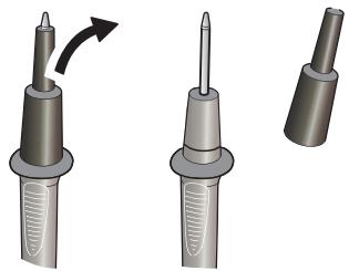
Operating instructions

Warning :
The probes are equipped with plastic caps to guarantee the highest level of security to the user during operations (CAT III / CAT IV). These caps can be removed to allow deeper penetration of the probes if needed (sockets voltage tests for example) but with a reduced level of security.
natural_image
Illustration of three different types of electrical probes with a curved arrow indicating rotation (no text or symbols present)
natural_image
Illustration of a tool inserted into a socket with wires (no text or symbols)