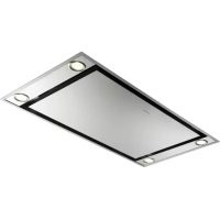
RANCH - Range hood FABER - Free user manual and instructions
Find the device manual for free RANCH FABER in PDF.
| Product type | Range hood |
| Brand | FABER |
| Model | RANCH |
| Available width | 60 cm, 90 cm, 120 cm |
| Power supply | 220-240 V ~ 50/60 Hz |
| Minimum distance to cooking surface | 650 mm |
| Number of speeds | 3 (minimum, medium, maximum) |
| Lighting | Bulbs (see type table) |
| Exhaust type | Extracting or recirculating (with charcoal filter) |
| Air outlet diameter | 150 mm or 120 mm (with reducer) |
| Grease filters | Self-supporting metal, dishwasher safe |
| Active charcoal filter | Non-washable, replace every 4 months approx. |
| Electrical class | Class I (grounding required) |
| Motor power | Not specified |
| Noise level | Varies with speed |
| Weight | Not specified |
Frequently Asked Questions - RANCH FABER
User questions about RANCH FABER
0 question about this device. Answer the ones you know or ask your own.
Ask a new question about this device
Download the instructions for your Range hood in PDF format for free! Find your manual RANCH - FABER and take your electronic device back in hand. On this page are published all the documents necessary for the use of your device. RANCH by FABER.
USER MANUAL RANCH FABER
The Instructions for Use apply to several versions of this appliance. Accordingly, you may find descriptions of individual features that do not apply to your specific appliance.
INSTALLATION
- The manufacturer will not be held liable for any damages resulting from incorrect or improper installation.
- The minimum safety distance between the cooker top and the extractor hood is 650~mm (some models can be installed at a lower height, please refer to the paragraphs on working dimensions and installation).
- Check that the mains voltage corresponds to that indicated on the rating plate fixed to the inside of the hood.
- For Class I appliances, check that the domestic power supply guarantees adequate earthing.
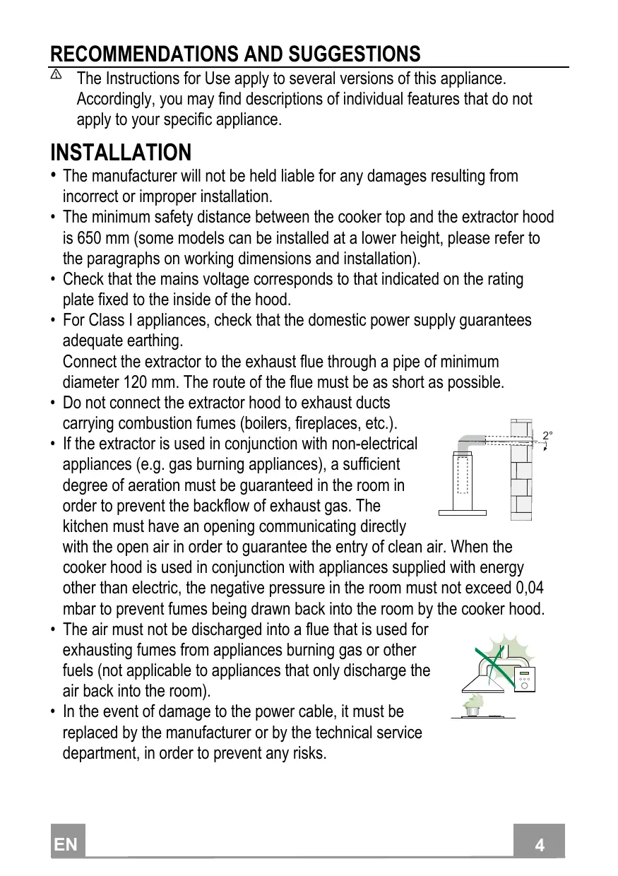
Connect the extractor to the exhaust flue through a pipe of minimum diameter 120mm . The route of the flue must be as short as possible.
- Do not connect the extractor hood to exhaust ducts carrying combustion fumes (boilers, fireplaces, etc.).
- If the extractor is used in conjunction with non-electrical appliances (e.g. gas burning appliances), a sufficient degree of aeration must be guaranteed in the room in order to prevent the backflow of exhaust gas. The kitchen must have an opening communicating directly
with the open air in order to guarantee the entry of clean air. When the cooker hood is used in conjunction with appliances supplied with energy other than electric, the negative pressure in the room must not exceed 0,04 mbar to prevent fumes being drawn back into the room by the cooker hood.
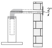
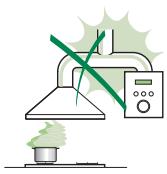
- The air must not be discharged into a flue that is used for exhausting fumes from appliances burning gas or other fuels (not applicable to appliances that only discharge the air back into the room).
- In the event of damage to the power cable, it must be replaced by the manufacturer or by the technical service department, in order to prevent any risks.
- If the instructions for installation for the gas hob specify a greater distance specified above, this has to be taken into account. Regulations concerning the discharge of air have to be fulfilled.
- Use only screws and small parts in support of the hood.
Warning: Failure to install the screws or fixing device in accordance with these instructions may result in electrical hazards.
- Connect the hood to the mains through a two-pole switch having a contact gap of at least 3mm .
USE
- The extractor hood has been designed exclusively for domestic use to eliminate kitchen smells.
- Never use the hood for purposes other than for which it has been designed.
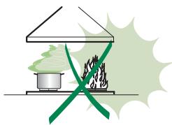
- Never leave high naked flames under the hood when it is in operation.
- Adjust the flame intensity to direct it onto the bottom of the pan only, making sure that it does not engulf the sides.
- Deep fat fryers must be continuously monitored during use: overheated oil can burst into flames.
- Do not flambé under the range hood; risk of fire.
- This appliance can be used by children aged from 8 years and above and persons with reduced physical, sensory or mental capabilities or lack of
experience and knowledge if they have been given supervision or instruction concerning use of the appliance in a safe way and understand the hazards involved. Children shall not play with the appliance. Cleaning and user maintenance shall not be made by children without supervision.
-
This appliance is not intended for use by persons (including children) with reduced physical, sensory or mental capabilities, or lack of experience and knowledge, unless they have been given supervision or instruction concerning use of the appliance by a person responsible for their safety.
-
“CAUTION: Accessible parts may become hot when used with cooking appliances.”
MAINTENANCE
- Switch off or unplug the appliance from the mains supply before carrying out any maintenance work.
- Clean and/or replace the Filters after the specified time period (Fire hazard).
- The Grease filters must be cleaned every 2 months of operation, or more frequently for particularly heavy usage, and can be washed in a dishwasher.
- The Activated charcoal filter is not washable and cannot be regenerated, and must be replaced approximately every 4 months of operation, or more frequently for particularly heavy usage.
- "Failure to carry out cleaning as indicated will result in a fire hazard".
- Clean the hood using a damp cloth and a neutral liquid detergent.
The symbol on the product or on its packaging indicates that this product may not be treated as household waste. Instead it shall be handed over to the applicable collection point for the recycling of electrical and electronic equipment. By ensuring this product is disposed of correctly, you will help prevent potential negative consequences for the environment and human health, which could otherwise be caused by inappropriate waste handling of this product. For more detailed information about recycling of this product, please contact your local city office, your household waste disposal service or the shop where you purchased the product.
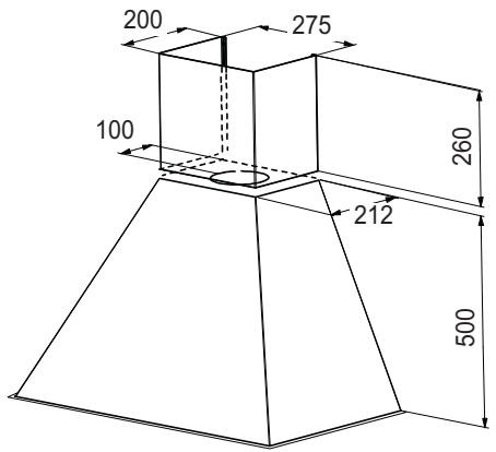
Dimensions
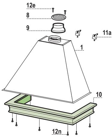
Components
| Ref. | Q.ty | Product Components |
| 1 | 1 | Hood Body, complete with: Controls, Light, Blower, Filters |
| 2 | 1 | Chimney |
| 8 | 1 | Air Outlet Grill |
| 9 | 1 | Reducer Flangeø 150-120 mm |
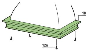
| 10 | 1 | Shelf Frame (optional) |
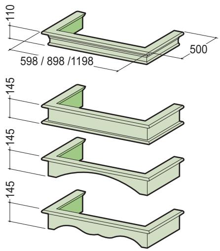
| 20 | 1 | Wooden Profile (optional) |
| Ref. | Q.ty | Installation Components |
| 7.2 | 1 | Chimney Fixing Brackets |
| 11 | 2 | Wall Plugs |
| 11a | 2 | Wall Plugs SB 12/10 |
| 12a | 2 | Screws 4,2 x 44,4 |
| 12e | 2 | Screws 2,9 x 12,7 |
| 12m | 6 | Screws 2,9 x 18 |
| 12n | 7 | Screws 3,5 x 16 |
| Q.ty | Documentation | |
| 1 | Instruction Manual |
Wall drilling and bracket fixing
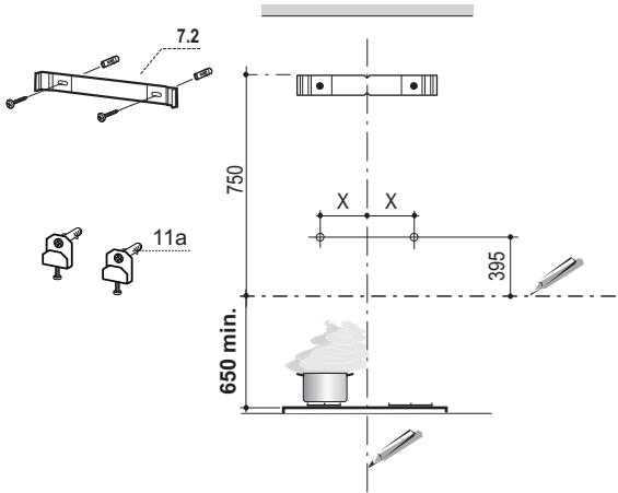
| Hood dimension | share X |
| 60 cm | 128 mm |
| 90 cm | 150 mm |
| 120 cm | 175 mm |
Wall marking:
- Draw a vertical line on the supporting wall up to the ceiling, or as high as practical, at the centre of the area in which the hood will be installed.
- Draw a horizontal line at 650mm above the hob.
- Mark a reference point as indicated at X mm (see X on picture) from the vertical reference line and 395 mm above the horizontal reference line.
- Repeat this operation on the other side.
- Drill at the points marked, using a 12mm drill bit.
- Insert the bracket plugs 11a into the holes and screw into place.
- Place bracket 7.2 on the wall as shown, 750mm above the horizontal reference line, aligning the centre (notch) with the vertical reference line.
- Mark the wall at the centres of the holes in the bracket.
- Drill 8 mm holes at all the centre points marked.
- Insert the wall plugs 11 in the holes.
Fix the brackets using the 12a screws (4,2× 44,4) supplied.
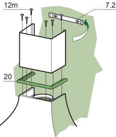
Flue assembly
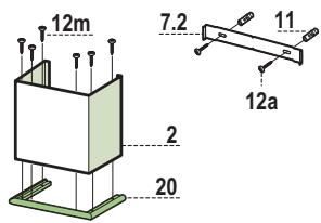
- Slightly widen the two sides of the flue and hook them behind the bracket 7.2, making sure that they are well seated.
- Insert the wooden profile 20 between the hood body and the flue.
Fix the lower section of the flue and the cable raceway to the hood body from above, using the 6 screws 12m (2.9 x 18) provided.
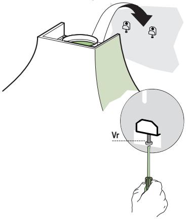
Mounting the hood body
- Adjust the two screws Vr_· on brackets 11a, to a minimum.
- Hook the hood canopy onto the two brackets 11a.
- Remove the metal grease filters by turning the handles provided.
- From inside the hood canopy, adjust the screws Vr to set the Hood Canopy level.
Connections
DUCTED VERSION AIR EXHAUST SYSTEM
When installing the ducted version, connect the hood to the chimney using either a flexible or rigid pipe 150 or 120mm , the choice of which is left to the installer.
- To install a 0.120 ~mm air exhaust connection, insert the reducer flange 9 on the hood body outlet.
Fix the pipe in position using sufficient pipe clamps (not supplied). - Remove possible charcoal filters.
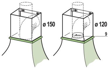
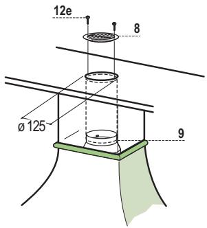
RECIRCULATION VERSION AIR OUTLET
- Cut a hole 125 mm in any shelf that may be positioned over the hood.
- Insert the reducer flange 9 on the hood body outlet.
- Connect the flange to the outlet on the shelf over the hood by using a flexible or rigid pipe 120mm .
Fix the pipe in position using sufficient pipe clamps (not supplied).
Fix the air outlet grid 8 on the recirculation air outlet by using the 2 screws 12e (2,9 x 9,5) provided. - Ensure that the activated charcoal filters have been inserted.

ELECTRICAL CONNECTION
- Connect the hood to the mains through a two-pole switch having a contact gap of at least 3mm .
- Remove the grease filters (see paragraph Maintenance) being sure that the connector of the feeding cable is correctly inserted in the socket placed on the side of the fan.

Fitting Shelf frame
- Rest the shelf frame 10 (optional) over the bottom edge of the hood body, aligning the fixing holes.
Fix from below using the 4 screws 12n (3.5× 16) provided..
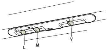
| L | Light | Switches the lighting system on and off |
| M | Motor | Switches the extractor motor on and off |
| V | Speed | Sets the operating speed of the extractor:1. Low speed, used for a continuous and silent air change in the presence of light cooking vapour.2. Medium speed, suitable for most operating conditions given the optimum treated air flow/noise level ratio.3. Maximum speed, used for eliminating the highest cooking vapour emission, including long periods. |
Grease filters
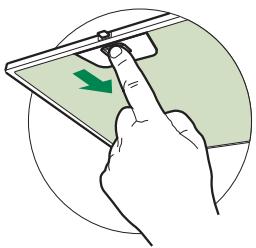
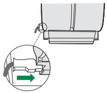
CLEANING METAL SELF- SUPPORTING GREASE FILTERS
- The filters must be cleaned every 2 months of operation, or more frequently for particularly heavy usage, and can be washed in a dishwasher.
- Remove the filters one at a time by pushing them towards the back of the group and pulling down at the same time.
- Wash the filters, taking care not to bend them. Allow them to dry before refitting.
- When refitting the filters, make sure that the handle is visible on the outside.
Activated charcoal filter (Recirculation version)
These filters are not washable and cannot be regenerated, and must be replaced approximately every 4 months of operation, or more frequently with heavy usage.
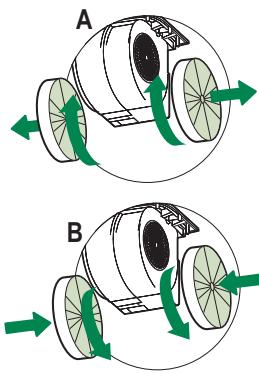
REPLACING THE ACTIVATED CHARCOAL FILTER
- Remove the metal grease filters
- Remove the saturated activated charcoal filter as shown (A).
- Fit the new filters (B).
- Replace the metal grease filters.

Lighting
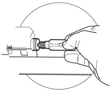
LIGHT REPLACEMENT
28W-40W light.
- Remove the metal grease filters.
- Unscrew the bulbs and replace them with new ones having the same characteristics.
- Replace the metal grease filters.
| Lamp | Power (W) | Socket | Voltage (V) | Dimension (mm) | ILCOS Code |
| 28 | E14 | 220 – 240 | 104 x 35 | HSGSB/C/UB-28-220/240-E14 | |
| 28 | E14 | 230 | 85x25 | HDG-28-230-E14-25 | |
| 20 | G4 | 12 | 33 x 9 | HSG/C/UB-20-12-G4 | |
| 35 | GU10 | 230 | 51 x 50,7 | HAGS-35-230-GU10-51/40 | |
| 50 | GU10 | 230 | 51 x 50,7 | HAGS-35-230-GU10-51/20 | |
| 20 | GU4 | 12 | 40 x 35 | HRGS-20-12-GU4-35/30 | |
| 20 | GU5.3 | 12 | 46 x 51 | HRGS-20-12-GU5.3-50/10 | |
| 16 | G13 | 95 | 720 x 26 | FD-16/40/1B-E-G13-26/720 | |
| 18 | G13 | 57 | 589,8 x 26 | FD-18/40/1B-E-G13-26/600 | |
| 9 | G23 | 60 (lamp) 220-240 (starter) | 167 x 28 | FSD-9/27/1B-I-G23 | |
| 11 | G23 | 91 (lamp) 220-240 (starter) | 235,8 x 28 | FSD-11/40/1B-I-G23 |
BbIpyCK BO3dYXA I3 BCACbIBAIOUe BbITJXKIN
IIyycTaHOBKN BcacbIBaIOIeB bITJXKN CoEINHHTbe c BbIyckHOI Tpy6oN JecTKOIN HIN rH6KOIN Tpy6Koi DnAmEtPOM 150 HIN 120 MM, TIN KOTopoN MoKeT Bbl-6paTB MOHTaXHHK.
- JIa coeHHeHH Tpyok0 120 MM BCTaBnIb IepexOJIbI bIaHeI9BBbIIyCKHOEOTBePcTHe KOpHyCa BBJIKN.
3aKpeINITb Tpy6ky COOTBeTCTBYIOUHMN Tpy6HbIMN 3aJHMamH. Heo6XoINMbI KpeIeKHBi MaTePnJI He BXOINTB KOMIIJEKT. - BbHyTb ΦHJIbTpbl OT 3aIIaXOB Ha aKTHBHOM yIe.

BbIXoD BO3IyXa I3 ΦNJIbTPYIOUeB BbITJXKIN
CJIeIaTb BIOJIke HaI BbITJIKKo OTBepCTne 0 125MM.
BcTaBnTb IepexoIhBn _IIaHeI9 B BVbIXOHOe OTBepCTHe B KOpIyCe BbITJxKn.
CoeHHHTb JIaHeu C BbIyucKbIM OTBepCThem IOJIKN HaD BBITJAKKO JcEeKoH HIN r6KO Tpy60 120 MM.
3aKpeHb Ty6y COOTBeCTBMyHMn 3aKHMamH. Heo6xoHMBI IJIg 3TOrO MaTePnaJI He BXoJIT B KOMJIeKT IOCTaBKn.
3aKpeINITb peIeTky 8Ha bblnyckHOM OTBepCTHN 2 BnHTamn 12e (2,9x9,5) (PpHlaHOTc).
- IIpoBepHTb HaJIInHe B BbITJxKke 03aIaxOB Ha aKTHBOM yTJE.
3JIeKTPnueCKOEIOJIKJIOUHHE
CoeINHHnB BbITJgKc C cTeBBIM HapJrKeHHem, yCTaHOHB INByXIOJIIOCHbI BbIKJIIOyAteJIb C pa3BeJeHHem KOHTAKTOB He MeHee 3 MM.
- CHaTb IpoTHBOKHnPOBbIe ΦHJIbTpbl (CMOTPN pa3JeI "YxOJ) H IpoBepHTb IIpaBNIbHOCTb IOJIooKeHHraPa3BeMa IINTaHOIIero Ka6eJI B PO3Etke BBITXKKn
YcTaHOBka pAMKn IOnIKN
- IIpHIOKHTb paMKy IJIЯ IOJIKN K CTHe 10 HaI HNJKHM KpaEM KOpIpyCa BbITaKKN H BbIPOBHrTb KpeIIeKHbIe OTBepCTHa.
3aKpeIHTb paMKy cHn3y IIpHJIaIraeMbIMN 4 BnHTaMn 12n (3,5 x 16).


L OcBeIeHHe BkJIIOHaeT N bblKJIIOHaeT OcBETHeJbHoe o6OpyIOBaHHe
M Motop BKJIOHaET N BbIKJIOHaET MOTOP BCaCbBAHn
V Ckopooctb PeryIInpyeT pa6Ouyo ckopooctb:
1.MHHMaJIbHna ckOpocTb - IIpiIroDHa IJIa HeIIpepbIBHOcMeHbI BO3dyxa IIpH HJIuHnMaJIOKoJIuYeCTBa Inpa OT rOTOBKn; OTJIuHaeTCB 6ecIiymHoCTbIO pa6Otbl.
2.CpeHnra ckopocb -PnroHa IJI HAn6OJIbIeJ uactn ycIOBn 3KcIIpyataHH 6JIaOJaAp OJIINHOMy COOTHOIIeHNIO IByX NOKa3aTeJIe: IIPOIyckHna CIOOC6Hocb Tb opa6oTaHHOR BO3Dyxa H yPoBeHb IIyMa.
3.MakchmaJIbHa cKOpocTb -IprHroDHa IJIA o6pa6OTKn HAn6OJIbIIHX HcIapEHn OT rOTOBKn DaKe B TeueHHe IJIHTeJIbHO BpeMeHH.
IpoTnBOxNpOBoBie qnlbTpbl
OuNCTKA METAJIINUECKNX IPOTNBOXIKPOBbIX ΦЛьТРОВ
Takoi hJIbTp MoJHO TaKHe MbITB B IocyIOMOeHoi MaIIHNHe. Mblr hJIbTp Heo6xOIMHO he peKe OJHO ra3a B 2 MeCya HIN Yauie B CJlyae erO aKTHBHOrO IIpHMHeHH.
CnHbHJIbTp,IIa Yero IpiKaTb ero K 3aJHei cSTOPHe y3Ja H OJHOBpeMeHHO IOTrHyTB BHN3.
- IIOMbIb ΦHJIbTp, CJIeIa 3a TeM, YTO6bl OH He IIOrHyJIcR, H JaTb EMy IIPOCOxHyTb.
- IocTaBnTb fHJIbTp Ha MeTo TaK, YTO6bI pyUka HaxOJHJIacb c HapyKHOi CTOpOHbI H 6bJIa BnDHa.

ΦnNbTpOT3anaxOB(ΦnNbTppyuOuaBbITaXka)
Takoi HJIbTp HeJIb3a MbITb H BOCCTaHaBJIINBaTb, eO cJIeJyET MeHrTB CpeIhEm pa3 B 4 MecIa HJI IN daKe YaIe B CJIyuae OCO60 HHTeHcHBHO HcIIIOJIb3OBaHHBbITJKKN.
3AMEHA YTOJIbHOrO ΦNJIbTPA HA AKTINBHOM YJJE
BbHytIpoTHBOKHNPOBBieΦNJIbTpbl.
- BbHytB HacbIeHHbIe HJIbTpBI OT 3aIIaxOB Ha aKTINBHOM yrJIe, KAK IOKa3aHO Ha pncyHke (A).
- IIOCTaBHTb HOBbIe _II JBtpb, KaK IOKa3aHO Ha pHCyHKe (B).
3aKpeINITb IIPOTHBOXKnPOBbIe HJIbTpbl.
3AMEHA JAMNIOYEK
2 JIaJIbI 28-40 Br
BbHytmbetaJIInueckneIpoTHBOKnOpOBbIE hJbtpbl.
OTBHHTHTb JAMIIIOUKN H 3aMeHHTb HX Ha HOBBie c TaKHMn Je XapaKTepHCTHKAMN.
- YCTaHOBHTb MeTaJIINHeCKHe IpOTHBOKHpOBbIe ΦJIbTpbl.

| Пампа | ПOT repeлени (ВТ) | Патрон | Нарражени (В) | Размер (MM) | КоД ILCOS |
| 28 | E14 | 220 - 240 | 104 x 35 | HSGSB/C/UB-28-220/240-E14 | |
| 28 | E14 | 230 | 85x25 | HDG-28-230-E14-25 | |
| 20 | G4 | 12 | 33 x 9 | HSG/C/UB-20-12-G4 | |
| 35 | GU10 | 230 | 51 x 50,7 | HAGS-35-230-GU10-51/40 | |
| 50 | GU10 | 230 | 51 x 50,7 | HAGS-35-230-GU10-51/20 | |
| 20 | GU4 | 12 | 40 x 35 | HRGS-20-12-GU4-35/30 | |
| 20 | GU5.3 | 12 | 46 x 51 | HRGS-20-12-GU5.3-50/10 | |
| 16 | G13 | 95 | 720 x 26 | FD-16/40/1B-E-G13-26/720 | |
| 18 | G13 | 57 | 589,8 x 26 | FD-18/40/1B-E-G13-26/600 | |
| 9 | G23 | 60 (памма) 220-240 (nускател) | 167 x 28 | FSD-9/27/1B-I-G23 | |
| 11 | G23 | 91 (памма) 220-240 (nускател) | 235,8 x 28 | FSD-11/40/1B-I-G23 |