GIGAVIDEO 570 - Wireless video transmitter MARMITEK - Free user manual and instructions
Find the device manual for free GIGAVIDEO 570 MARMITEK in PDF.

User questions about GIGAVIDEO 570 MARMITEK
0 question about this device. Answer the ones you know or ask your own.
Ask a new question about this device
Download the instructions for your Wireless video transmitter in PDF format for free! Find your manual GIGAVIDEO 570 - MARMITEK and take your electronic device back in hand. On this page are published all the documents necessary for the use of your device. GIGAVIDEO 570 by MARMITEK.
USER MANUAL GIGAVIDEO 570 MARMITEK
- To prevent short circuits, this product should only be used inside and only in dry spaces. Do not expose the components to rain or moisture. Do not use the product close to a bath, swimming pool etc.
- Do not expose the components of your systems to extremely high temperatures or bright light sources.
- Do not open the product: the device contains live parts. The product should only be repaired or serviced by a qualified repairman.
In case of improper usage or if you have opened, altered and repaired the product yourself, all guarantees expire. Marmitek does not accept responsibility in the case of improper usage of the product or when the product is used for purposes other than specified. Marmitek does not accept responsibility for additional damage other than covered by the legal product responsibility. - Adapters: Only connect the adapter to the mains after checking whether the mains voltage is the same as the values on the identification tags. Never connect an adapter or power cord when it is damaged. In that case, contact your supplier.
This product is not a toy. Keep out of reach of children.
CONTENTS
1 INTRODUCTION 3
2 SET CONTENTS 3
3. SETTING UP THE TRANSMITTER 4
4. SETTING UP THE RECEIVER 4
5. SETTING UP THE IR EXTENDER FEATURE 5
6. FINE TUNING THE GigaVideo570TM SET 5
7. HOW DO I CONNECT THE GigaVideo570™ TO MY PC 5
8. USING THE GigaVideo570TM SET 6
9. FREQUENTLY ASKED QUESTIONS 6
10 TECHNICAL DATA 8
1. INTRODUCTION.
Congratulations on buying the Marmitek GigaVideo570™! It enables you to transmit the signal of your Video recorder, DVD-player, DVD-recorder, Satellite receiver, set top box, PC etc. to your (second) TV without running wires. It enables you to connect 2 sources simultaneously and simply switch between both signals without changing plugs. With the GigaVideo570™ you can also transmit films from your PC to the TV in the living room or bedroom, transmit MP3 audio to your Hifi system and monitor your baby or patients by using your video camera, all from a remote location. The built-in infra-red extension feature enables you to control your A/V devices with your own remote remote control and control the two connected sources from the room where you watch TV! Using the 5,8GHz frequency, you will normally have no problems with distortion from wireless (WiFi) networks, microwave for example.
2. SET CONTENTS.
1 Transmitter
1 Receiver
2 Power adapters
1 IR Extender cable with 3 LEDs.
1 3,5 mm jackplug / RCA adapter (audio)
3 Mini-DIN / RCA cables (white / red / yellow).
1 RCA cable (white / red / yellow)
2 Scart adapters (labelled Transmitter).
1 Scart adapter (labelled Receiver)
1 Scart adapter (labelled AV OUT).
1 user manual
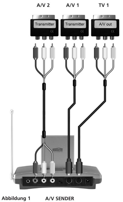
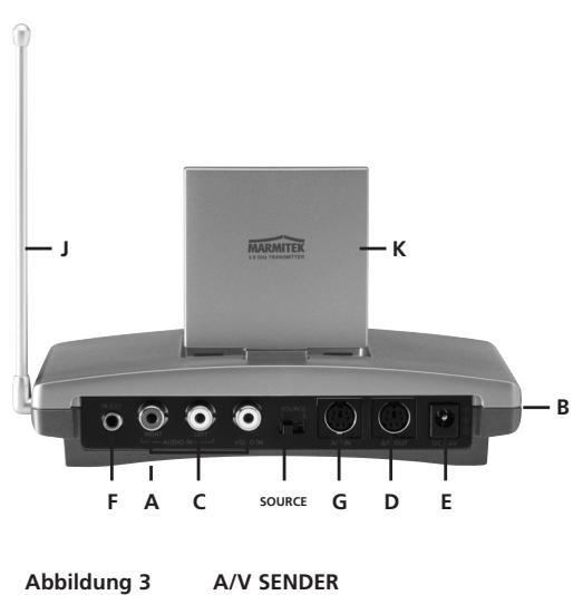
3. SETTING UP THE TRANSMITTER.
See figures 1 and 3.
The transmitter can be connected to two A/V devices and a local TV.
- Switch the Power slide switch [B] into the 'OFF' position.
- Connect the RCA/RCA cable to the 'A/V IN 2' [C] or the Mini-DIN/RCA cable on the 'A/V IN 1' [G] of the transmitter.
- Connect the RCA plugs of this cable to the A/V device you want to transmit the signal from. Make sure the colours of the plugs and the input connectors match. If the A/V device is equipped with a scart connector you can also connect the transmitter using the scart adapter labelled 'TRANSMITTER'.
- In order to also connect the AV device to 'TV1' (your local TV), insert a Mini -DIN/RCA cable between the 'AV OUT' of the transmitter and your 'TV1'. If this TV is equipped with a scart connector you can also connect the transmitter using the included scart adapter labelled 'AV OUT'.
- Set to channel selector [A] (A-B-C-D) to A.
- Insert the plug of one of the power adapters in the 'DC in' [E] on the back of the transmitter and plug the power adapter included into a wall socket (230V-50Hz). Please use only the adapter provided!
- Turn the On/Off switch [B] to 'ON'.
- Place the transmitter in an easy accessible spot with enough space around it. Aim the inside (flat side) of the dish antenna [K] at the location of the receiver.
- Put the side antenna [J] in an upright position.
- Repeat steps 1 to 3 to set up the second A/V device and then turn the On/Off switch [B] to 'ON' again.
Video signal and S-VIDEO signal
The connector on the back of the transmitter is no S-VIDEO connector. This is why you can't connect S-VIDEO signals to the Marmitek GigaVideo570™ but only 'ordinary' video signals. If you only have S-VIDEO output on your AV device or PC (you can recognize an S-VIDEO connection by a small round mini DIN plug with 4 pins), then you can use the Marmitek S-VIDEO to composite video adapter (art. no. 09388, not included).
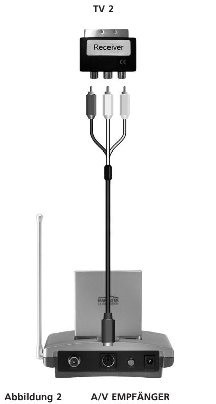
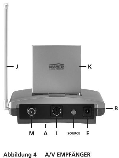
4. SETTING UP THE RECEIVER.
See figures 2 and 4.
- Turn the On/Off switch [B] to 'OFF'.
- Connect the Mini-DIN/RCA cable on the outputs at the backside of the receiver [L].
- Plug the other end of this cable into the A/V input of TV2 or the video recorder. Make sure the colours of the plugs and the input connectors match. If the TV is equipped with a scart connector then you can also connect the transmitter using the included scart adapter labelled 'RECEIVER'.
Tip: The GigaVideo570 set is provided with a modulator. Using this, you can also connect the receiver to your TV via an antenna cable. This is ideal when your TV is not provided with a SCART input (antenna cable not additionally supplied). Link the GigaVideo570 to your TV via the RF output [M]. During the use of the RF output, your TV should be tuned on channel 36.
- Insert the plug of the remaining power adapter into the DC input [E] on the back of the receiver and plug the power adapter included into a wall socket (230V-50Hz). Please use only the adapter provided!
- Turn the On/Off switch [B] to 'ON'.
-
Set to channel selector [A] (A-B-C-D) to A.
-
Place the receiver in an easy accessible spot with enough space around it, e.g. on top of the TV. Point the inside (flat side) of the dish antenna [K] at the location of the transmitter.
- Put the side antenna [J] in an upright position.
5. SETTING UP THE IR EXTENDER FEATURE.
- Connect the IR Extender included to the input [F] at the back of the transmitter (see figure 3).
- Remove the small paper protective label of one of the IR emitters. Place this IR emitter on the IR window of the A/V device you want to control. Affix the emitter very lightly. Before affixing the IR emitter firmly you are advised to check if the extender works properly. Therefore point your own remote at the window on the front of the receiver and press some of the channel choose buttons. If the channel does not change, the IR emitter may not be fixed in the right position. The position is sometimes critical. Repeat this procedure for fixing the 2nd IR emitter to the other A/V device connected.
- You can use the third IR to control a third AV device. If you are not using this IR emitter, don't remove it!
6. FINE TUNING THE GigaVideo570™ SET.
Make sure your AV equipment is switched on.
When the receiver on your TV is connected with RCA plugs and/or a SCART adapter: Switch the TV, to which you have connected the receiver, over to the TV channel, which belongs to the A/V input, on which you have connected the receiver. In case of most appliances, you do that by pressing the 0 or A/V button. You will now have an image directly. The TV will never have to look for channels for the connection via 'A/V IN'.
When the receiver on your TV is connected to the RF output: Switch the TV, to which you have connected the receiver, over to TV channel 36.
The wireless GigaVideo570™ usually works best with the flat faces of the antennas [K] on the Transmitter and Receiver unit look at one another. Sometimes however distance, reflections and other effects in the home may affect the signal so that some adjustment of either Transmitter or Receiver antenna may be necessary to get the best signal. If still experiencing difficulty, try changing the "ABCD" channel selector [A] and change channels. Remember though both the receiver and transmitter must be on the same channel.
The maximum distance between transmitter and receiver depends on local circumstances, but on average the distance is up to 30m , through walls and floors. If you experience signal problems please read chapter 9: Frequently Asked Questions.
7. HOW DO I CONNECT THE GigaVideo570™ TO MY PC.
The GigaVideo570™ has to be connected to the 'TV-out' or 'Video-out' of your PC. The connection can usually be found on the graphics card. The signal needs to be a so-called 'composite video signal'. This is also called 'CVBS'. Connecting to a PC can be done with RCA/RCA on A/V1b as well as RCA/mini-DIN on A/V2.
The connector of your graphics card can look as follows (see figure 5):
Yellow RCA connector (RCA Yellow)

If your PC is fitted with this connector, the yellow plug of the RCA cable included can be directly connected to the yellow RCA connector of your transmitter.
DIN-plug (S-VIDEO)
If your graphics card is fitted with the S-VIDEO-connector you cannot directly connect the transmitter to your PC but need an adapter. This adapter 'converts' your S-VIDEO-signal into a composite video signal. This adapter is usually supplied with the graphics card (or PC) with TV-out. You can also get this adapter from your Marmitek dealer. (See figure 6; Art.nr. 09388).

TV Out (S-video)
Figure 6
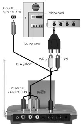
Figure 5
This standard adapter does not fit on all PCs. In that case, please contact the supplier of the graphics card. To use the TV-out some settings in the graphics card menu need to be changed. This is different for each PC and operating system, but usually the correct mode needs to be selected. Select 'composite', 'CVBS' or 'PAL-G'. More information can usually be found in the PC manual or graphics card manual. Because there are so many different types of graphics cards, we cannot offer any support.
To transmit sound, you can use the audio out on the sound card of your PC. Please use an adapter to convert the 3.5mm plug to a double RCA connection.
8. USING THE GigaVideo570TM SET.
- Make sure your AV device is switched on.
- Switch the receiving TV over to the TV transmitter going with the A/V input you plugged the receiver into. Normally done by using the 0 or A/V button. The picture should now automatically be there. No tuning is required.
When you make use of the modulator [M], it should be done in channel 36. - Then you can control your A/V device with your own remote control by pointing it at the IR window of the receiver or the IR window of your A/V device. The source can also be switched by keeping the source button [S] at the backside of the receiver pressed for about 5 seconds. You can switch sources at 'TV 1' (where the transmitter is connected), by setting the SOURCE button [S] (at the backside of the transmitter) in the right position, so the device switches over.
- 2 external A/V devices can be connected to the transmitter.
Selecting the source:
Using 'TV2' (connected to the receiver), you can change sources by pressing any button of a remote control for at least 8 seconds (e.g. of your TV or AV device).
Independent of the signal on 'TV1' you can select a signal for 'TV2'.
9. FREQUENTLY ASKED QUESTIONS.
I get no signal.
- Check that the units are connected to mains and that the Power-switch is in the ON position
- Check that both units in the 'ON' position [B].
- Check if the receiving TV is on the correct AV channel. Raise the small black side antenna [J] to an upright position.
The signal received is poor.
Try another channel (A, B, C or D; the channel settings must be the same on both units).
- Move transmitter and/or receiver from the immediate vicinity of the connected A/V devices. These may affect the range.
You are (almost) out of range.
- Moving the position of the transmitter and/ or receiver a few centimetres may rectify the problem.
The images and sound are perfect, but the infra-red return signal does not work.
Check the following:
- Depending on the local situation the 5.8GHz AV signal can reach further than the 433MHz signal of the IR receiver. Try again with shorter distances.
- Has the IR emitter been properly connected to the transmitter?
- Has the IR emitter been properly fixed on the IR window of your AV device?
I do get images but no sound.
- The GigaVideo570™ can send analogue stereo signals, such as e.g. Dolby Surround. Digital systems such as Dolby 5.1 or Dolby Digital cannot be transmitted.
- You have connected an S-VIDEO (Mini-DIN) signal to the transmitter directly with an S-VIDEO cable. This is not possible. You need to use the cables included and connect them to the scart or RCA output of your A/V device.
Does the GigaVideo570™ cause a conflict with my wireless network (WLAN)?
No, WiFi makes use of the 2.4Ghz frequency band. The GigaVideo570 makes use of the 5.8GHz frequency band. In cases where a 2.4GHz video transmitter experiences distortion from a WiFi network, for example, then the GigaVideo570 can be the right solution
Can I combine multiple receivers?
Yes. However, the signal will be the same on all receivers.
Can I combine multiple transmitters?
You can use a maximum of 4 transmitters with one or more receivers. You can use 4 different channels. The infrared return channel cannot be set separately and will work with the entire system. Transmitters and receivers of GigaVideo570™ are not compatible with transmitters and receivers that operate on a 2.4GHz frequency band.
Do you still have questions? Check out www.marmitek.com for more information.
TECHNICAL DATA
GigaVideo570TM TRANSMITTER
| Range: | Up to 100m free field, up to 30m through walls and ceilings |
| Power: | 230VAC/50Hz, 7.2VDC adapter 320mA. |
| Frequency: | A/V: 5.8GHz, 4 channels (A, B, C, D). |
| IR: 433.92 MHz. | |
| A/V input: | 1x Mini-DIN (A/V IN) |
| 1x 3x RCA (A/V IN 1x Video 2x Audio) | |
| A/V output: | 1x Mini-DIN (AV OUT) |
| Video input: | 1Vpp (typ) 75Ω |
| Audio input: | 1Vpp (typ) 600Ω |
| Audio: | Stereo. |
| Dimensions: | 140x100x140mm (with upright antenna) |
GigaVideo570TM RECEIVER
| Power: | 230VAC/50Hz, 7.2VDC adapter 250mA. |
| Frequency: | A/V: 5.8GHz, 4 channels (A, B, C, D). |
| A/V output: | 3x RCA (AV OUT 1x Video 2x Audio) |
| RF output PAL-B/G: | Transmitter 36 |
| RF output PAL-I: | Transmitter 48 |
| Video output: | 1Vpp (type) / 75Ω |
| Audio output: | 1Vpp (type) / 600Ω |
| Audio: | Stereo. |
| Dimensions: | 92x58x20mm (with upright antenna) |

Environmental Information for Customers in the European Union
European Directive 2002/96/EC requires that the equipment bearing this symbol on the product and/or its packaging must not be disposed of with unsorted municipal waste. The symbol indicates that this product should be disposed of separately from regular household waste streams. It is your responsibility to dispose of this and other electric and electronic equipment via designated collection facilities appointed by the govern-
ment or local authorities. Correct
disposal and recycling will help prevent potential negative consequences to the environment and human health. For more detailed information about the disposal of your old equipment, please contact your local authorities, waste disposal service, or the shop where you purchased the product.
SICHERHEITSHINWEISE
9. QUESTIONS SOUVENT POSEES.
Alimentation: 230VAC/50Hz, 7.2VDC 250mA.
Fréquence: A/V: 5,8GHz, 4 canaux (A, B, C, D).
AV sortie: 3x RCA (AV OUT 1xCDéo 2x Audio).
Dimensions: 92x58x20mm.

VEILIGHEIDSWAARSCHUWINGEN
DECLARATION OF CONFORMITY
Hereby, Marmitek BV, declares that this GigaVideo570 is in compliance with the essential requirements and other relevant provisions of the following Directives:
Directive 1999/5/EC of the European Parliament and of the Council of 9 March 1999 on radio equipment and telecommunications terminal equipment and the mutual recognition of their conformity
DIRECTIVE 2004/108/EC OF THE EUROPEAN PARLIAMENT AND OF THE COUNCIL of 15 December 2004 on the approximation of the laws of the Member States relating to electromagnetic compatibility
Directive 2002/95/EC of the European Parliament and of the Council of 27 January 2003 on the restriction of the use of certain hazardous substances in electrical and electronic equipment
DECLARATION OF CONFORMITY
Marmitek is a trademark of Marmidenko BV I GigaVideo570™ is a trademark of Marmitek BV. All rights reserved.
Copyright and all other proprietary rights in the content (including but not limited to model numbers, software, audio, video, text and photographs) rests with Marmitek B.V. Any use of the Content, but without limitation, distribution, reproduction, modification, display or transmission without the prior written consent of Marmitek is strictly prohibited. All copyright and other proprietary notices shall be retained on all reproductions.