
HV301 - GNSS Receiver TRIMBLE - Free user manual and instructions
Find the device manual for free HV301 TRIMBLE in PDF.
User questions about HV301 TRIMBLE
0 question about this device. Answer the ones you know or ask your own.
Ask a new question about this device
Download the instructions for your GNSS Receiver in PDF format for free! Find your manual HV301 - TRIMBLE and take your electronic device back in hand. On this page are published all the documents necessary for the use of your device. HV301 by TRIMBLE.
USER MANUAL HV301 TRIMBLE
Trimble Construction
Instruments Division
5475 Kellenburger Road,
Dayton, Ohio 45424-1099
U.S.A.
+1-937-233-8921 Phone
www.trimble.com
HV301
Bedienungsanleitung
User Guide
Electromagnetic compatibility 89/336/EEC.
Kaiserslautern, 18.06.2003
Bernd Brieger
Geschäftsführer
TABLE OF CONTENTS
FOR YOUR SAFETY 12
Important Information 12
COMPONENTS 13
SETTING TO WORK 13
Rotation mode 13
Pointing mode 13
Line/scanning mode 14
Self-leveling and Height Change alert 14
LEVELING ACCURACY 14
Influences on Leveling Accuracy 14
Accuracy Check 14
OPERATING EXAMPLES 15
Marking Heights 15
Adjusting in Parallel 16
Right Angles/Vertical Mode 16
Transferring marks to the Ceiling - Plumb Point 16
POWER SUPPLY 17
Installing Batteries 17
Operating Time 17
Charging 17
PROTECTING THE UNIT 17
CLEANING AND MAINTENANCE 17
PROTECTING THE ENVIRONMENT 17
WARRANTY 18
TECHNICAL DATA 18
FOR YOUR SAFETY

LASER RADIATION AVOID DIRECT EYE EXPOSURE CLASS 3R LASER PRODUCT
- Do not remove warning labels from the unit.
- The laser is subject to class 3R (< 5mW, 600 ... 680 nm).
- Never look into the laser beam or direct it to the eyes of other people.
- Always operate the unit in a way that prevents the beam from getting into people's eyes.
Important Information
Always mark in the center of the laser beam
- Always place the laser in the middle of the working area
- Tripod/wallmount operation is recommended for distances over 65 feet (20 m)
- Check the accuracy regularly
- Stable mounting is necessary for secure operations
- Keep the glass of the instrument clean
COMPONENTS
Buttons
1 Power button
2 Scan size button
3 Speed and Rotation button
4 Down arrow button
5 Up arrow button
Control indicators
6 Leveling Indicator
7 Manual/Warning Indicator
8 Battery Indicator
9 Infrared-receiver for remote control
Elements of the unit
10 Beam aperture/prism cap
11 Elastic rubber boot
12 Handle
13 Center Marks
14 Battery door
15 5/8x 11 Tripod Mounts
16 Rubber feet
SETTING TO WORK
Before using the unit for the first time, install alkaline or rechargeable batteries. Charge rechargeable batteries. See battery section.
Position the unit horizontally or vertically (tripod mount and rubberfeet downward!) on a stable platform, wallmount or tripod at the desired elevation. The unit recognizes automatically whether it is used horizontally or vertically when switched on.
Press the power button 1 to turn on the unit. Self-leveling will start at once. In order to switch the unit off, press the power button again. The unit is leveled when the leveling indicator 6 is no longer flashing (once every second). The rotor will not spin until the unit is leveled. For the first five minutes after the laser self levels, the LED lights solid then flashes every four seconds to let you know the laser is still level.
After turning on the unit and after self-leveling, the unit starts with the last chosen mode. Using "set and forget" during self-leveling after turning on the unit, the scan size and position, and rotation speed can be chosen while the laser beam will be emitted.
If the unit is positioned beyond it's self-leveling range of ± 8% , the laser and leveling indicators will recurringly flash quickly four times. Turn the unit off, reposition the laser within the self-leveling range and turn it on again.
Rotation mode
By pressing the speed/rotation button 3 the unit is set into rotation mode. Line mode is stopped.
Pressing the button again, rotation speed will toggle through 600, 200, 80, 10 and 0min^-1 . At 10 rpm a small laser line will increase visibility of the rotating beam.

When pressing the buttons on the keypad, the unit may temporarily become out of level due to its high accuracy. The motor will not rotate until it has self-levelled again.
Select the highest rotation speed (600 rpm) for use with an electronic detector.
Pointing mode
When using the pointing mode, the laser visibility will be at its highest because the entire laser energy is focused on one point. Turn the prism by hand or press the arrow buttons 4 and 5 on the keypad to the desired position.
During horizontal operation, by pressing the arrow buttons, the prism is moved gradually counterclockwise or clockwise (360^) .
During vertical operation, the laser point may be positioned precisely or may be adjusted parallel right- or leftwards on a ± 8% range.
By pressing and holding the buttons, the movement of the point will be accelerated.
Line/scanning mode
By pressing and releasing the scan size button 2, the unit is set to scan mode. Rotation mode is stopped.
The unit starts at an opening angle of 8 degrees. Pressing the button again increases the angle to 45, 90 and 180 degrees.
By pressing and holding the scan size button 2 a programmable scan zone can be created by turning the prism manually from the desired start-to the desired end-point. After releasing button 2, the created line will be performed at actual speed.
By pressing the arrow buttons 4 and 5 the scan zone may be moved clockwise or counterclockwise. By pressing and holding the buttons, the movement will be accelerated.

When pressing the buttons on the keypad, the unit may temporarily become out of level due to its high accuracy.
Manual mode/Single Slope mode
By pressing the 'M' button on the remote control or the receiver-remote control, the unit is set from automatic self-leveling mode to Manual mode. Manual mode is indicated by the flashing (once every second) red LED 7. In Manual mode, the Y-axis can be sloped by pressing the Up- and Down-Arrow buttons on the unit's keypad or the remote control. Additionally, the X-axis can be sloped by pressing the Left- and Right-Arrow buttons on the remote control.
By pressing the 'M' button again in horizontal operation, the unit is set into Single Slope mode. This is indicated by the flashing red 7 and green 6 LEDs (once every second). In vertical setup, pressing the 'M' button again switches the unit back to automatic self leveling mode. In Single Slope mode, the Y-axis can be sloped by pressing the Up- and Down-Arrow-buttons on the unit's keypad or the remote control, while the X-axis remains in automatic self leveling mode (e.g. when setting up sloped ceilings or drive ways). Operates the unit in Rotation at 600 rpm, the Height change (HI) alert is still active.
Self-leveling, Height change (HI) alert
Once turned on, the unit automatically levels itself in ranges of 8% ( ± 0,8 ~m / 10 ~m ; 8 ft/100ft)). In order to recognize the leveling process at the measuring area and in order not to mark faulty heights during this operation, the rotation stops.
Once leveled, the unit constantly monitors its level condition. The Height change (HI) alert is activated 5 minutes after self-leveling was performed and the laser is rotating at 600min^-1 .
Level errors >30mm / 10m (1-1/8inch/10ft) put the unit into alert mode because they are generally caused by a disturbance which could lead to inaccurate measurements. When entering into alert mode, the prism stops, the beam turns off, a warning sound is heard and the HI Warning LED 7 flashes 2x per second. Turn the unit off and then on again. To assure your former elevation, now you have to check or arrange the exact height.
LEVELING ACCURACY
Influences on the leveling accuracy
The overall accuracy of the unit can be influenced by many factors:
- factory accuracy;
temperature of the unit; - ambient influences like rain, wind and temperature.
The factor which influences on the unit's accuracy most is the ambient temperature. Vertical differences in temperature near the ground can divert the laser beam, similar to the heat waves seen on hot asphalt streets.

This factor also applies to all optical measuring devices such as automatic levels and theodolites.
Accuracy Check
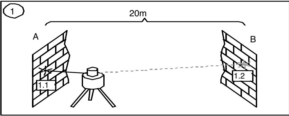
To ensure job-site accuracy, you need a distance of 20 m (65 feet) between two walls A and B, where you will execute 4 measuring operations on a tripod as follows (transit measurement).
Set the unit horizontally on a tripod near wall A and switch it on with the plus-X-axis pointing towards wall A. After the unit is level, mark the height of the laser spot at the centre of the beam at wall A. Turn the entire unit 180^ , let it self-level and mark the center of the laser spot at wall B.
Now, place the unit near wall B with the plus-X-axis pointing towards wall B. After the unit is level, mark the height of the laser spot at the centre of the beam at wall B. Turn the entire unit 180^ , let it self-level and mark the center of the laser spot at wall A. The difference (h) of the marked points at wall A shows the deviation.
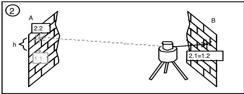
If the unit is within its working accuracy limits (± 30^ ) , the maximum difference from true level at 20m (65 ft.) + 20m (65 ft.) = 40m (130 ft.) is 6mm (1/4 inch). The highest and the lowest mark may be up to 12mm (1/2 inch) apart.
Repeat the above steps for "minus x" and for "plus-" and "minus y", so that a measurement for all four axes of the unit have been performed.
If the visibility of the laser beam is bad, you can use a detector to transfer the heights to the walls. The accuracy of the detector has to be regarded.
OPERATING EXAMPLES
Marking Heights
Put the instrument in horizontal mode (e.g. when using a tripod or wallmount) so that the laser beam is at the desired height. Then either turn the prism manually to the desired area or use one of the rotation modes.
When working without a tripod or wallmount, put the instrument on a stable base and measure the height difference between laser beam and desired height by using a ruler. After turning the prism to the desired area, mark the measured height again.
Adjusting in Parallel
In order to measure irregularities, create right angles, align partitions in right angles or to mark vertical lines, the direct beam (plumb beam) has to be adjusted parallel which means the laser beam has to be placed in the same offset distance to a wall or any other reference line.
Therefore place and align the unit in vertical mode, so that the beam runs roughly in parallel to a wall or other reference line. Measure the distance between the beam and the wall near the unit and at a certain distance.
To adjust the beam in parallel, press the line button 4 or 5 to realize the same offset distance at the unit and far away.
The procedure for aligning an extension joint is similar. Just position the unit so that the beam runs directly above the joint.

A long reference distance is important for accuracy. Therefore it should be as long as possible.
Right Angles/Vertical Mode
Set up the unit in vertical mode so that the perpendicular beam is parallel to a reference line (e.g. a wall). The rotating laser beam is now at a right angle from your original point and as a vertical area available.
The best visibility is reached by using the line mode (e.g. as a perpendicular).
Transferring marks to the Ceiling - Plumb Point
The origin of the laser beam is located directly above the horizontal tripod mount and the height of the vertical tripod mount.
In order to transfer a marked point from the bottom to the ceiling, there are center marks 13 at the lower part of the unit's housing. Using these marks, the unit may be set up with the two axes X and Y above two crossed chalk marks, for example.

For better installation of the unit above a mark on the floor, just mark 2 rectangular lines through this point.
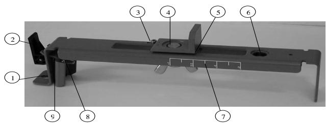
WALL MOUNT M300 (optional)
- Nail Hole - allows you to hang the wall mount onto a nail or screw.
- Locking Lever - opens/closes the clamp.
- Stop Screw - stops the sliding bracket from moving beyond a set point on the wall mount. The screw can be moved so that the center of the beam aligns with the wall molding 0.0cm (0.0 in.) or (3.1 cm (1 ~in.)
- 5 / 8'' - 11 Laser Mount – lets you connect the laser to the wall mount and holds the sliding bracket in place after it has been positioned along the elevation scale.
- Reading Edge - allows you to adjust the laser position appropriate for your application needs.
- 5/8"-11 Tripod Mount - lets you connect the wall mount to a standard tripod when using in vertical mode.
- Elevation Scale - provides graduated marks that indicate the position of the laser relative to the wall-molding height. The adjustment range on the scale is from 3.1cm (1 in.) above wall-molding height to 5cm (2 in.) below it. (The -2^ position is aligned with the horizontal centerline at the ceiling target.)
- Lock Nut - lets you adjust the clamping force.
- Clamp - opens/closes so that the wall mount can be attached to wall molding or floor track.
POWER SUPPLY
Installing Batteries
Remove the battery door by turning the centerscrew 90^ counterclockwise. Insert batteries (or a rechargeable battery pack) into the housing so that the negative poles are on the larger battery spiral springs. Install the battery door and tighten it by turning the centerscrew 90^ clockwise.

A mechanical switch prevents alkaline batteries from being charged. Only the original rechargeable batterie pack allows charging within the unit. Any other rechargeable batteries have to be charged externally.
Operating Time
Rechargeable batteries permit an operating time of appr. 40 hours in rotation mode.
Alkaline batteries (AlMn) permit an operating time of appr. 30 hours in rotation mode.
The following factors reduce the operating time:
- frequent self-leveling due to wind or vibration;
- extreme temperatures;
- old rechargeable batteries or rechargeable batteries with Memory-effect;
- using batteries of different capacities.

Remove all batteries at the same time, never use batteries with different capacities, only use new (charged) batteries (rechargeable).
Low voltage is indicated by slow flashing of the battery indicator 8.
Charging rechargeable batteries
The charger requires appr. 10 hours to charge empty rechargeable batteries. For this charging, connect the plug of the charger to the recharge jack of the unit. The charging function is indicated by a red display at the charger. New or long time out of use rechargeable batteries reach their best performance after being charged and recharged five times.

The batteries should only be charged when the laser is between 50^ and 104^ ( 10^ to 40^ ) Charging at a higher temperature may damage the batteries. Charging at a lower temperature may increase the charge time and decrease the charge capacity, resulting in loss of performance and shortened life expectancy.
PROTECTING THE UNIT
Do not expose the unit to extreme temperatures or temperature changes (do not leave inside the car).
The unit is very robust and can resist damage if dropped even from tripod height. Before continuing your work, always check the leveling accuracy. See Accuracy Check section.
The laser is water proof and can be used indoors and outdoors.
CLEANING AND MAINTENANCE
Dirt and water on the glass parts of laser or prism will influence beam quality and operating range considerably. Clean with cotton swabs.
Remove dirt on the housing with a lint-free, warm, wet and smooth cloth. Do not use harsh cleansers or solvents. Allow the unit to air dry after cleaning it.
PROTECTING THE ENVIRONMENT
The unit, accessories and packaging ought to be recycled.
This manual is made of non-chlorine recycling paper.
All plastic parts are marked for recycling according to material type.

Do not throw used batteries into the garbage, water or fire. Remove them in compliance with environmental requirements.
WARRANTY
According to legal regulations, the warranty-period for this unit is 12 months for material and manufacturing defaults.
We do not take any liability for damages caused by a non-accurate unit.

Before starting to work, always carry out the Accuracy Check according to the corresponding chapter.
This warranty is no longer valid if the unit is opened or the labels are removed.
TECHNICAL DATA
| Leveling accuracy1,3: | ≤±1 mm/10m, 1/8" @ 100 ft, 20 arc seconds |
| Rotation: | 4 speed levels |
| appr. 10/80/200/600 rpm | |
| Operational area1,2: | appr. 100 m (330 feet) radius with detector |
| Laser type: | red diode laser 635 nm |
| Laser class: | Class 3R, <5mW |
| Self-leveling range: | appr. ±5° |
| Leveling time: | appr. 30 sec |
| Leveling indicators: | LED flashes |
| Laser beam diameter1: | appr. 5 mm |
| Power supply: | 4 x 1.5V Mono cells type D (LR20) |
| Operating temp.: | 23°F...113°F (-5°C ... 45°C) |
| Storage temp.: | -4°F...158°F (-20°C ... 70°C) |
| Tripod attachments: | 5/8 x 11 horizontally and vertically |
| Weight: | 2.7 kg (5.9 lbs) |
| Low voltage indication: | flashing/shining of the battery indicator |
| Low voltage disconnection: | unit shuts off |
1) at 21^ Celsius
2) under optimal atmospheric circumstances
3) along the axis
DECLARATION OF CONFORMITY
We
Trimble Kaiserslautern GmbH declare under our sole responsibility that the product HV301 to which this declaration relates is in conformity with the following standards EN 61000-4-2, 1994; EN 55022, 1994; EN 61000-4-3, 1997 following the provisions of directive Electromagnetic compatibility 89/336/EEC.
The managing director
Electro-Magnetic Compatibility Declaration of Conformity
This digital apparatus does not exceed the Class B Limits for radio noise for digital apparatus set out in the Radio Interference Regulations of the Canadian Department of Communications.
This device complies with part 15 off the FCC rules. Operation is subject to the condition that this device does not cause harmful interference.
Note: The product been tested and found to comply with the limits for a Class B digital device, pursuant to part 15 of the FCC rules. These limits are designed to provide reasonable protection against harmful interference in a residential installation. The product generates, uses and can radiate radio frequency energy and, if not installed and used in accordance with the instructions, may cause harmful interference to radio or television reception, which can be determined by turning the product off and on. The user is encouraged to try to eliminate the interference by one or more of the following measures:
- Reorient or relocate the receiving antenna.
- Increase the separation between the product and the receiver.
- For more information, consult your dealer or an experienced radio/television technician.
Caution: Changes or modifications to the product that are not expressly approved by Trimble could void authority to use the equipment.
SOMMAIRE

Electromagnetic compatibility 89/336/EEC.
Kaiserslautern, 06-06-2003
Electromagnetic compatibility 89/336/EEC.
Kaiserslautern 2003-06-05
Bernd Brieger
Electromagnetic compatibility 89/336/EEC.
Kaiserslautern, 06.06.2003
Bernd Brieger
Direktør
INDICE

PARA A SUA SEGURANCA 61
61
ELEMENTOS DO APARELHO 62
Electromagnetic compatibility 89/336/EEC.
Kaiserslautern, 06.06.2003
Bernd Brieger
Foretningsforer
Electromagnetic compatibility 89/336/EOK.
model 10/80/200/600 1/dak.
Electromagnetic compatibility 89/336/EEC