
DC745KA - Cordless drill driver DEWALT - Free user manual and instructions
Find the device manual for free DC745KA DEWALT in PDF.

| Product type | Cordless drill driver |
| Brand | DEWALT |
| Model | DC745KA |
| Rated voltage | 12 Vdc |
| Compatible battery type | NiCd/NiMH (12 V battery packs) |
| Power output | 240 W |
| No-load speed (1st gear) | 0–400 rpm |
| No-load speed (2nd gear) | 0–1,450 rpm |
| Impact rate (1st gear) | 0–6,800 rpm |
| Impact rate (2nd gear) | 0–25,000 rpm |
| Maximum torque | 35 Nm |
| Chuck capacity | 13 mm (keyless) |
| Max drilling capacity (wood) | 28 mm |
| Max drilling capacity (metal) | 13 mm |
| Max drilling capacity (masonry) | 13 mm |
| Weight (without battery pack) | 1.44 kg |
| Sound pressure level (LpA) | 83 dB(A) (uncertainty K=3 dB) |
| Sound power level (LWA) | 94 dB(A) (uncertainty K=3 dB) |
| Vibration (drilling metal) | 1.40 m/s² (uncertainty K=1.58 m/s²) |
| Vibration (drilling concrete) | 7.8 m/s² (uncertainty K=2.7 m/s²) |
| Main functions | Drilling, screwdriving, hammer (hammer drill) |
| Included accessories | 2 battery packs, charger, kit box (K version), instruction manual |
| Compatible chargers | DE9130, DE9135, DE9116 (230 V~) |
| Maintenance and cleaning | Clean with dry air and soft cloth; do not use solvents |
| Safety | Double insulation, chuck brake, trigger lock, contact protector cover |
| Warranty | 1 year (parts and labor) + 30 days satisfaction guarantee |
Frequently Asked Questions - DC745KA DEWALT
User questions about DC745KA DEWALT
0 question about this device. Answer the ones you know or ask your own.
Ask a new question about this device
Download the instructions for your Cordless drill driver in PDF format for free! Find your manual DC745KA - DEWALT and take your electronic device back in hand. On this page are published all the documents necessary for the use of your device. DC745KA by DEWALT.
USER MANUAL DC745KA DEWALT
DC720
DC721
DC722
DC725
DC727
DC730
DC731
DC732
DC735
DC737
DC742
DC743
DC745
www.DEWALT.eu
| Dansk | 3 |
| Deutsch | 17 |
| English | 32 |
| Español | 45 |
| Français | 60 |
| Italiano | 75 |
| Nederlands | 90 |
| Norsk | 104 |
| Português | 117 |
| Suomi | 132 |
| Svenska | 145 |
| Türkçe | 158 |
| Ελληνικά | 172 |
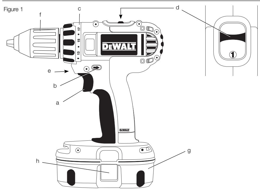
Figure 2
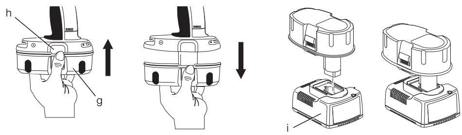
Figure 3
natural_image
Technical line drawing of a mechanical assembly with a component labeled A (no text or symbols present)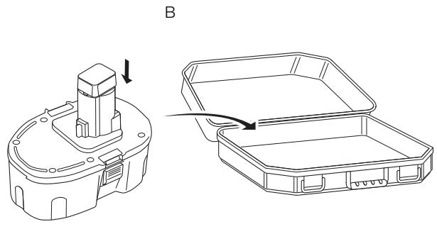
natural_image
Technical line drawing of a mechanical component with an arrow indicating assembly direction (no text or symbols present)Figure 4
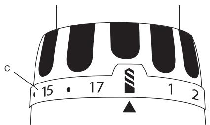
Figure 5
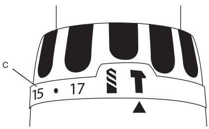
Figure 6
DC720, DC721, DC722, DC730, DC731, DC732, DC742, DC743 LEDNINGSFRI KOMPAKT BOREMASKINE/SKRUEMASKINE DC725, DC727, DC735, DC737, DC745 LEDNINGSFRI KOMPAKT BOREMASKINE/SKRUEMASKINE/SLAGBOREMASKINE
Tillykke!
DC720, DC721, DC722, DC725, DC727, DC730, DC731, DC732, DC735, DC737, DC742, DC743, DC745
DEWALT erklærer, at disse produkter, som er beskrevet under "tekniske data" er konstrueret i overensstemmelse med: 98/37/E∅F (indtil 28. dec 2009), 2006/42/EC (fra 29. dec 2009), 2004/108/EC, 2006/95/EC, EN 55014-1, EN 55014-2, EN 60745-1, EN 60745-2-1, EN 60745-2-2.
DC720, DC721, DC722, DC730, DC731, DC732, DC742, DC743 KOMPAKTE AKKU-BOHRMASCHINEN/-BOHRSCHRAUBER DC725, DC727, DC735, DC737, DC745 KOMPAKTE AKKU-BOHRMASCHINEN/-BOHRSCHRAUBER/- BOHRHAMMERHERZLICHEN
Glückwunsch!
DC720, DC721, DC722, DC725, DC727, DC730, DC731, DC732, DC735, DC737, DC742, DC743, DC745
DC720, DC721, DC722, DC730, DC731, DC732, DC742, DC743 CORDLESS COMPACT DRILL/DRIVERS DC725, DC727, DC735, DC737, DC745 CORDLESS COMPACT DRILL/DRIVER/HAMMERDRILL
Congratulations!
You have chosen a DEWALT tool. Years of experience, thorough product development and innovation make DEWALT one of the most reliable partners for professional power tool users.
Technical data
| DC720 | DC721 | DC722 | DC725 | DC727 | DC730 | DC731 | ||
| Voltage | V_DC | 18 | 18 | 18 | 18 | 18 | 14.4 | 14.4 |
| Battery Type | NiCd/NiMH | NiCd/NiMH | Li-Ion | NiCd/NiMH | Li-Ion | NiCd/NiMH | NiCd/NiMH | |
| Power output | W | 400 | 400 | 375 | 400 | 375 | 295 | 295 |
| No-load speed | ||||||||
| 1st gear | min^-1 | 0-500 | 0-500 | 0-500 | 0-500 | 0-500 | 0-400 | 0-400 |
| 2nd gear | min^-1 | 0-1700 | 0-1700 | 0-1700 | 0-1700 | 0-1700 | 0-1450 | 0-1450 |
| Impact rate | ||||||||
| 1st gear | min^-1 | - | - | - | 0-8500 | 0-8500 | - | - |
| 2nd gear | min^-1 | - | - | - | 0-29000 | 0-29000 | - | - |
| Max. torque | Nm | 40 | 44 | 41 | 44 | 41 | 35 | 40 |
| Chuck capacity | mm | 10 | 13 | 13 | 13 | 13 | 10 | 13 |
| Maximum drilling capacity | ||||||||
| Wood | mm | 38 | 38 | 38 | 38 | 38 | 35 | 35 |
| Metal | mm | 10 | 13 | 13 | 13 | 13 | 10 | 13 |
| Masonry | mm | - | - | - | 13 | 13 | - | - |
| Weight (without battery pack) | kg | 1.35 | 1.36 | 1.36 | 1.46 | 1.46 | 1.34 | 1.35 |
| DC732 | DC735 | DC737 | DC742 | DC743 | DC745 | |||
| Voltage | V_DC | 14.4 | 14.4 | 14.4 | 12 | 12 | 12 | |
| Battery Type | Li-Ion | NiCd/NiMH | Li-Ion | NiCd/NiMH | NiCd/NiMH | NiCd/NiMH | ||
| Power output | W | 270 | 295 | 270 | 240 | 240 | 240 | |
| No-load speed | ||||||||
| 1st gear | min^-1 | 0-400 | 0-400 | 0-400 | 0-400 | 0-400 | 0-400 | |
| 2nd gear | min^-1 | 0-1450 | 0-1450 | 0-1450 | 0-1450 | 0-1450 | 0-1450 | |
| Impact rate | ||||||||
| 1st gear | min^-1 | - | 0-6800 | 0-6800 | - | - | 0-6800 | |
| 2nd gear | min^-1 | - | 0-25000 | 0-25000 | - | - | 0-25000 | |
| Max. torque | Nm | 37 | 40 | 37 | 32 | 35 | 35 | |
| Chuck capacity | mm | 13 | 13 | 13 | 10 | 13 | 13 | |
| Maximum drilling capacity | ||||||||
| Wood | mm | 35 | 35 | 35 | 28 | 28 | 28 | |
| Metal | mm | 13 | 13 | 13 | 10 | 13 | 13 | |
| Masonry | mm | - | 13 | 13 | - | - | 13 | |
| Weight (without battery pack) | kg | 1.35 | 1.45 | 1.45 | 1.33 | 1.34 | 1.44 | |
ENGLISH
| DC720 | DC721 | DC722 | DC725 | DC727 | DC730 | DC731 | ||
| L_pA (sound pressure) | dB(A) | 76 | 76 | 76 | 83 | 83 | 76 | 76 |
| K_pA (sound pressure uncertainty K) | dB(A) | 3 | 3 | 3 | 3 | 3 | 3 | 3 |
| L_WA (acoustic power) | dB(A) | 87 | 87 | 87 | 94 | 94 | 87 | 87 |
| K_WA (acoustic power uncertainty K) | dB(A) | 3 | 3 | 3 | 3 | 3 | 3 | 3 |
Vibration total values (triax vector sum) determined according to EN60745:
| Vibration emission value a_h | ||||||||
| Drilling into metal | ||||||||
| a_hD = | m/s2 | 1.15 | 1.15 | 1.15 | 1.40 | 1.40 | 1.15 | 1.15 |
| Uncertainty K = | m/s2 | 1.70 | 1.70 | 1.70 | 1.58 | 1.58 | 1.70 | 1.70 |
| Vibration emission value a_h | ||||||||
| Drilling into concrete | ||||||||
| a_hID = | m/s2 | - | - | - | 7.8 | 7.8 | - | - |
| Uncertainty K = | m/s2 | - | - | - | 2.7 | 2.7 | - | - |
| DC732 | DC735 | DC737 | DC742 | DC743 | DC745 | ||
| L_pA (sound pressure) | dB(A) | 76 | 83 | 83 | 76 | 76 | 83 |
| K_pA (sound pressure uncertainty K) | dB(A) | 3 | 3 | 3 | 3 | 3 | 3 |
| L_WA (acoustic power) | dB(A) | 87 | 94 | 94 | 87 | 87 | 94 |
| K_WA (acoustic power uncertainty K) | dB(A) | 3 | 3 | 3 | 3 | 3 | 3 |
Vibration total values (triax vector sum) determined according to EN60745:
| Vibration emission value a_h | |||||||
| Drilling into metal | |||||||
| a_hD = | m/s2 | 1.15 | 1.40 | 1.40 | 1.15 | 1.15 | 1.40 |
| Uncertainty K = | m/s2 | 1.70 | 1.58 | 1.58 | 1.70 | 1.70 | 1.58 |
| Vibration emission value a_h | |||||||
| Drilling into concrete | |||||||
| a_hID = | m/s2 | - | 7.8 | 7.8 | - | - | 7.8 |
| Uncertainty K = | m/s2 | - | 2.7 | 2.7 | - | - | 2.7 |
The vibration emission level given in this information sheet has been measured in accordance with a standardised test given in EN 60745 and may be used to compare one tool with another. It may be used for a preliminary assessment of exposure.

WARNING: The declared vibration emission level represents the main applications of the tool. However if the tool is used for different applications, with different accessories or poorly maintained, the vibration emission may differ. This may significantly increase the exposure level over the total working period.
An estimation of the level of exposure to vibration should also take into account the times when the tool is switched off or when it is running but not actually doing the job. This may significantly reduce the exposure level over the total working period.
Identify additional safety measures to protect the operator from the effects of vibration such as: maintain the tool and the accessories, keep the hands warm, organisation of work patterns.
ENGLISH
| Battery pack | DE9180 | DE9503 | DE9095 | DE9098 | DE9140 | |
| Battery type | Li-Ion | NiMH | NiCd | NiCd | Li-Ion | |
| Voltage | V_DC | 18 | 18 | 18 | 18 | 14.4 |
| Capacity | A_h | 2.0 | 2.6 | 2.0 | 1.3 | 2.0 |
| Weight | kg | 0.68 | 1.0 | 1.0 | 0.87 | 0.58 |
| Battery pack | DE9094 | DE9091 | DE9074 | DE9501 | DE9071 | |
| Battery type | NiCd | NiCd | NiCd | NiMH | NiCd | |
| Voltage | V_DC | 14.4 | 14.4 | 12 | 12 | 12 |
| Capacity | A_h | 1.3 | 2.0 | 1.3 | 2.6 | 2.0 |
| Weight | kg | 0.60 | 0.70 | 0.55 | 0.69 | 0.65 |
| Charger | DE9130 | DE9135 | DE9116 | |
| Mains voltage | V_AC | 230 | 230 | 230 |
| Battery type | NiCd/NiMH | NiCd/NiMH/Li-Ion | NiCd/NiMH | |
| Approx. charging time | min | 30(2.0 Ah battery packs) | 40(2.0 Ah battery packs) | 60(2.0 Ah battery packs) |
| Weight | kg | 0.5 | 0.52 | 0.4 |
| Fuses: | ||
| Europe | 230 V tools | 10 Amperes, mains |
| U.K. & Ireland | 230 V tools | 13 Amperes, in plugs |
Definitions: Safety Guidelines
The definitions below describe the level of severity for each signal word. Please read the manual and pay attention to these symbols.

DANGER: Indicates an imminently hazardous situation which, if not avoided, will result in death or serious injury.

WARNING: Indicates a potentially hazardous situation which, if not avoided, could result in death or serious injury.

CAUTION: Indicates a potentially hazardous situation which, if not avoided, may result in minor or moderate injury.
CAUTION: Used without the safety alert symbol indicates a potentially hazardous situation which, if not avoided, may result in property damage.

Denotes risk of electric shock.

Denotes risk of fire.
EC-Declaration of conformity

DC720, DC721, DC722, DC725, DC727, DC730, DC731, DC732, DC735, DC737, DC742, DC743, DC745
DEWALT declares that these products described under “technical data” have been designed in compliance with:
98/37/EEC (until Dec. 28, 2009), 2006/42/EC (from Dec. 29, 2009), 2004/108/EC, 2006/95/EC, EN 55014-1, EN 55014-2, EN 60745-1, EN 60745-2-1, EN 60745-2-2.
For more information, please contact DEWALT at the following address or refer to the back of the manual.
The undersigned is responsible for compilation of the technical file and makes this declaration on behalf of DEWALT.
$$ \chi . j o p s m a n $$
Horst Grossmann
Vice President Engineering and Product
Development
DEWALT, Richard-Klinger-Strase 11,
D-65510, Idstein, Germany
16/09/2007

WARNING: To reduce the risk of injury, read the instruction manual.
General Power Tool Safety Warnings

WARNING! Read all safety warnings and instructions Failure to follow the warnings and instructions may result in electric shock, fire and/or serious injury.
SAVE ALL WARNINGS AND INSTRUCTIONS FOR FUTURE REFERENCE.
The term “power tool” in the warnings refers to your mains-operated (corded) power tool or battery-operated (cordless) power tool.
1) WORK AREA SAFETY
a) Keep work area clean and well lit. Cluttered or dark areas invite accidents.
b) Do not operate power tools in explosive atmospheres, such as in the presence of flammable liquids, gases or dust. Power tools create sparks which may ignite the dust or fumes.
c) Keep children and bystanders away while operating a power tool. Distractions can cause you to lose control.
2) ELECTRICAL SAFETY
a) Power tool plugs must match the outlet. Never modify the plug in any way. Do not use any adapter plugs with earthed (grounded) power tools. Unmodified plugs and matching outlets will reduce risk of electric shock.
b) Avoid body contact with earthed or grounded surfaces such as pipes, radiators, ranges and refrigerators. There is an increased risk of electric shock if your body is earthed or grounded.
c) Do not expose power tools to rain or wet conditions. Water entering a power tool will increase the risk of electric shock.
d) Do not abuse the cord. Never use the cord for carrying, pulling or unplugging the power tool. Keep cord away from heat, oil, sharp edges or moving parts. Damaged or entangled cords increase the risk of electric shock.
e) When operating a power tool outdoors, use an extension cord suitable for outdoor use. Use of a cord suitable for outdoor use reduces the risk of electric shock.
f) If operating a power tool in a damp location is unavoidable, use a residual current device (RCD) protected supply. Use of an RCD reduces the risk of electric shock.
3) PERSONAL SAFETY
a) Stay alert, watch what you are doing and use common sense when operating a power tool. Do not use a power tool while you are tired or under the influence of drugs, alcohol or medication. A moment of inattention while operating power tools may result in serious personal injury.
b) Use personal protective equipment. Always wear eye protection. Protective equipment such as dust mask, non-skid safety shoes, hard hat, or hearing protection used for appropriate conditions will reduce personal injuries.
c) Prevent unintentional starting. Ensure the switch is in the off position before connecting to power source and/or battery pack, picking up or carrying the tool. Carrying power tools with your finger on the switch or energising power tools that have the switch on invites accidents.
d) Remove any adjusting key or wrench before turning the power tool on. A wrench or a key left attached to a rotating part of the power tool may result in personal injury.
e) Do not overreach. Keep proper footing and balance at all times. This enables better control of the power tool in unexpected situations.
f) Dress properly. Do not wear loose clothing or jewellery. Keep your hair, clothing and gloves away from moving parts. Loose clothes, jewellery or long hair can be caught in moving parts.
g) If devices are provided for the connection of dust extraction and collection facilities, ensure these are connected and properly used. Use of dust collection can reduce dust-related hazards.
ENGLISH
4) POWER TOOL USE AND CARE
a) Do not force the power tool. Use the correct power tool for your application.
The correct power tool will do the job better and safer at the rate for which it was designed.
b) Do not use the power tool if the switch does not turn it on and off. Any power tool that cannot be controlled with the switch is dangerous and must be repaired.
c) Disconnect the plug from the power source and/or the battery pack from the power tool before making any adjustments, changing accessories, or storing power tools. Such preventive safety measures reduce the risk of starting the power tool accidentally.
d) Store idle power tools out of the reach of children and do not allow persons unfamiliar with the power tool or these instructions to operate the power tool. Power tools are dangerous in the hands of untrained users.
e) Maintain power tools. Check for misalignment or binding of moving parts, breakage of parts and any other condition that may affect the power tool's operation. If damaged, have the power tool repaired before use. Many accidents are caused by poorly maintained power tools.
f) Keep cutting tools sharp and clean.
Properly maintained cutting tools with sharp cutting edges are less likely to bind and are easier to control.
g) Use the power tool, accessories and tool bits etc., in accordance with these instructions taking into account the working conditions and the work to be performed. Use of the power tool for operations different from those intended could result in a hazardous situation.
5) BATTERY TOOL USE AND CARE
a) Recharge only with the charger specified by the manufacturer. A charger that is suitable for one type of battery pack may create a risk of fire when used with another battery pack.
b) Use power tools only with specifically designated battery packs. Use of any other battery packs may create a risk of injury and fire.
c) When battery pack is not in use, keep it away from other metal objects like paper clips, coins, keys, nails, screws or other
small metal objects that can make a connection from one terminal to another. Shorting the battery terminals together may cause burns or a fire.
d) Under abusive conditions, liquid may be ejected from the battery, avoid contact. If contact accidentally occurs, flush with water. If liquid contacts eyes, additionally seek medical help. Liquid ejected from the battery may cause irritation or burns.
6) SERVICE
a) Have your power tool serviced by a qualified repair person using only identical replacement parts. This will ensure that the safety of the power tool is maintained.
ADDITIONAL SPECIFIC SAFETY RULES
Drill/Driver/Hammerdrill Safety Warnings
- Wear ear protectors with impact drills. Exposure to noise can cause hearing loss.
- Hold power tools by insulated gripping surfaces when performing an operation where the cutting tool may contact hidden wiring or its own cord. Cutting accessory contacting a “live” wire may make exposed metal parts of the tool “live” and shock the operator.
- Use auxiliary handles supplied with the tool. Loss of control can cause personal injury.
- Use clamps or other practical way to secure and support the workpiece to a stable platform. Holding the work by hand or against your body is unstable and may lead to loss of control.
- Wear ear protectors when hammering for extended periods of time. Prolonged exposure to high intensity noise can cause hearing loss. Temporary hearing loss or serious ear drum damage may result from high sound levels generated by hammerdrilling.
- Wear safety goggles or other eye protection. Hammering and drilling operations cause chips to fly. Flying particles can cause permanent eye damage.
- Hammer bits and tools get hot during operation. Wear gloves when touching them.
Labels on tool
DATE CODE POSITION
Date Code, which also includes the year of manufacture, is printed into the housing surface that forms the mounting joint between tool and battery!
Example:
2007 XX XX
Year of Manufacture
Important Safety Instructions for All Battery Chargers
SAVE THESE INSTRUCTIONS: This manual contains important safety and operating instructions for the DE9130, DE9135 and DE9116 battery chargers.
- Before using charger, read all instructions and cautionary markings on charger, battery pack, and product using battery pack.

DANGER: Electrocution hazard. 230 volts are present at charging terminals. Do not probe with conductive objects. Electric shock or electrocution may result.

WARNING: Shock hazard. Do not allow any liquid to get inside charger. Electric shock may result.

CAUTION: Burn hazard. To reduce the risk of injury, charge only DEWALT rechargeable batteries. Other types of batteries may burst causing personal injury and damage.

CAUTION: Under certain conditions, with the charger plugged in to the power supply, the exposed charging contacts inside the charger can be shorted by foreign material. Foreign materials of a conductive nature such as, but not limited to, steel wool, aluminum foil, or any buildup of metallic particles should be kept away from charger cavities. Always unplug the charger from the power supply when there is no battery pack in the cavity. Unplug charger before attempting to clean.
- DO NOT attempt to charge the battery pack with any chargers other than the ones in this manual. The charger and battery pack are specifically designed to work together.
• These chargers are not intended for any uses other than charging DEWALT
rechargeable batteries. Any other uses may result in risk of fire, electric shock or electrocution.
- Do not expose charger to rain or snow.
- Pull by plug rather than cord when disconnecting charger. This will reduce risk of damage to electric plug and cord.
- Make sure that cord is located so that it will not be stepped on, tripped over, or otherwise subjected to damage or stress.
- Do not use an extension cord unless it is absolutely necessary. Use of improper extension cord could result in risk of fire, electric shock, or electrocution.
- An extension cord must have adequate wire size (AWG or American Wire Gauge) for safety. The smaller the gauge number of the wire, the greater the capacity of the cable, that is 16 gauge has more capacity than 18 gauge. When using more than one extension to make up the total length, be sure each individual extension contains at least the minimum wire size.
- Do not place any object on top of charger or place the charger on a soft surface that might block the ventilation slots and result in excessive internal heat. Place the charger in a position away from any heat source. The charger is ventilated through slots in the top and the bottom of the housing.
- Do not operate charger with damaged cord or plug — have them replaced immediately.
- Do not operate charger if it has received a sharp blow, been dropped, or otherwise damaged in any way. Take it to an authorized service center.
- Do not disassemble charger; take it to an authorized service center when service or repair is required. Incorrect reassembly may result in a risk of electric shock, electrocution or fire.
- Disconnect the charger from the outlet before attempting any cleaning. This will reduce the risk of electric shock. Removing the battery pack will not reduce this risk.
- NEVER attempt to connect 2 chargers together.
- The charger is designed to operate on standard 230V household electrical power. Do not attempt to use it on any other voltage. This does not apply to the vehicular charger.
SAVE THESE INSTRUCTIONS
ENGLISH
Chargers
The DE9130 and DE9116 charger accepts 7.2 – 18 V NiCd and NiMH batteries.
The DE9135 charger accepts 7.2 – 18 V NiCd, NiMH or Li-Ion batteries.
These chargers require no adjustment and are designed to be as easy as possible to operate.
Charging Procedure

DANGER: Electrocution hazard. 230 volts present at charging terminals. Do not probe with conductive objects. Danger of electric shock or electrocution.
- Plug the charger (i) into an appropriate outlet before inserting battery pack.
- Insert the battery pack (g) into the charger. The red (charging) light will blink continuously indicating that the charging process has started.
- The completion of charge will be indicated by the red light remaining ON continuously. The pack is fully charged and may be used at this time or left in the charger.
Charging process
Refer the table below for the state of charge of the battery pack.
| State of charge | |
| charging | - - - - - - |
| fully charged | —— |
| hot/cold pack delay | — - — - |
| replace battery pack | ●●●●●●●●● |
| problem | ●● ●● ●● ●● |
Automatic refresh
The automatic refresh mode will equalise or balance the individual cells in the battery pack at its peak capacity. Battery packs should be refreshed weekly or whenever the pack no longer delivers the same amount of work.
To refresh your battery pack, place the battery in the charger as usual. Leave the battery pack for at least 8 hours in the charger.
Hot/Cold Pack Delay
When the charger detects a battery that is too hot or too cold, it automatically starts a Hot/Cold Pack Delay, suspending charging until the battery has reached an appropriate temperature. The charger
then automatically switches to the pack charging mode. This feature ensures maximum battery life.
DEEP DISCHARGE PROTECTION
The battery pack is protected against deep discharging when it is used in the tool.
Important Safety Instructions for All Battery Packs
When ordering replacement battery packs, be sure to include catalog number and voltage. Consult the chart at the end of this manual for compatibility of chargers and battery packs.
The battery pack is not fully charged out of the carton. Before using the battery pack and charger, read the safety instructions below. Then follow charging procedures outlined.
READ ALL INSTRUCTIONS
- Do not charge or use battery in explosive atmospheres, such as in the presence of flammable liquids, gases or dust. Inserting or removing the battery from the charger may ignite the dust or fumes.
- Charge the battery packs only in DEWALT chargers.
- DO NOT splash or immerse in water or other liquids.
- Do not store or use the tool and battery pack in locations where the temperature may reach or exceed 40^ C ( 105^ F) (such as outside sheds or metal buildings in summer).

DANGER: Electrocution hazard. Never attempt to open the battery pack for any reason. If battery pack case is cracked or damaged, do not insert into charger. Electric shock or electrocution may result. Damaged battery packs should be returned to service center for recycling.

WARNING: Never attempt to open the battery pack for any reason. If battery pack case is cracked or damaged, do not insert into charger. Do not crush, drop or damage battery pack. Do not use a battery pack or charger that has received a sharp blow, been dropped, run over or damaged in any way (i.e., pierced with a nail, hit with a hammer, stepped on). Damaged battery packs should be returned to service center for recycling.

CAUTION: When not in use, place tool on its side on a stable surface where it will not cause a tripping or falling hazard. Some tools with large battery packs will stand upright on the battery pack but may be easily knocked over.
SPECIFIC SAFETY INSTRUCTIONS FOR NICKEL CADMIUM (NiCd) OR NICKEL METAL HYDRIDE (NiMH)
- Do not incinerate the battery pack even if it is severely damaged or is completely worn out. The battery pack can explode in a fire.
- A small leakage of liquid from the battery pack cells may occur under extreme usage or temperature conditions. This does not indicate a failure.
However, if the outer seal is broken:
a. and the battery liquid gets on your skin, immediately wash with soap and water for several minutes.
b. and the battery liquid gets into your eyes, flush them with clean water for a minimum of 10 minutes and seek immediate medical attention. (Medical note: The liquid is 25-35% solution of potassium hydroxide.)
SPECIFIC SAFETY INSTRUCTIONS FOR LITHIUM ION (LI-ION)
- Do not incinerate the battery pack even if it is severely damaged or is completely worn out. The battery pack can explode in a fire. Toxic fumes and materials are created when lithium ion battery packs are burned.
- If battery contents come into contact with the skin, immediately wash area with mild soap and water. If battery liquid gets into the eye, rinse water over the open eye for 15 minutes or until irritation ceases. If medical attention is needed, the battery electrolyte is composed of a mixture of liquid organic carbonates and lithium salts.
- Contents of opened battery cells may cause respiratory irritation. Provide fresh air. If symptoms persist, seek medical attention.

WARNING: Burn hazard. Battery liquid may be flammable if exposed to spark or flame.
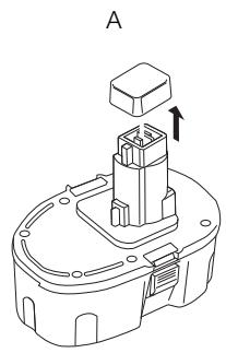
Battery Cap (fig. 3)
A protective battery cap is supplied to cover the contacts of a detached battery pack. Without the protective cap in place, loose metal objects could short circuit the contacts, causing a fire hazard and damaging the battery pack.
- Take off the protective battery cap before placing the battery pack in the charger or tool (Fig. 3A).
- Place the protective cap over the contacts immediately after removing the battery pack from the charger or tool (Fig. 3B).

WARNING: Make sure the protective battery cap is in place before storing or carrying a detached battery pack.
Battery pack (fig. 1)
BATTERY TYPE
The DC720, DC721, DC722, DC725 and DC727 operate on 18 volt battery packs.
The DC730, DC731, DC732, DC735 and DC737 operate on 14,4 volt battery packs.
The DC742, DC743 and DC745 operate on 12 volt battery packs.
Storage Recommendations
- The best storage place is one that is cool and dry away from direct sunlight and excess heat or cold.
- Long storage will not harm the battery pack or charger. Under proper conditions, they can be stored for 5 years or more.
Labels on charger and battery pack
In addition to the pictographs used in this manual, the labels on the charger and the battery pack show the following pictographs:

Read instruction manual before use.

Battery charging

Battery charged

Battery defective

Hot\cold pack delay

Do not probe with conductive objects.

Do not charge damaged battery packs
ENGLISH

Use only with DEWALT battery packs, others may burst, causing personal injury and damage.

Do not expose to water.

Have defective cords replaced immediately.

Charge only between 4 °C and 40 °C.

Discard the battery pack with due care for the environment.

Do not incinerate the battery pack NiMH, NiCd+ and Li-Ion.

NiMH + Charges NiMH and NiCd NiCd battery packs.

Li Ion Charges Li-Ion battery packs.

See technical data for charging time.
Package contents
The package contains:
1 Drill/Hammerdrill
2 Battery packs
1 Charger
1 Kitbox (K version only)
1 Instruction manual
1 Exploded drawing
NOTE: Battery packs and chargers are not included with N-models.
- Check for damage to the tool, parts or accessories which may have occurred during transport.
• Take the time to thoroughly read and understand this manual prior to operation.
Description (fig. 1)

WARNING: Never modify the power tool or any part of it. Damage or personal injury could result.
INTENDED USE
These drills/drivers/hammerdrills are designed for professional drilling and screwdriving applications.
DO NOT use under wet conditions or in presence of flammable liquids or gases.
These drills/drivers/hammerdrills are professional power tools. DO NOT let children come into contact with the tool. Supervision is required when inexperienced operators use this tool.
a. Trigger switch
b. Forward/reverse button
c. Torque adjustment collar
d. Gear selector
e. Worklight
f. Keyless chuck
g. Battery pack
h. Battery release buttons
Electrical safety
The electric motor has been designed for one voltage only. Always check that the battery pack voltage corresponds to the voltage on the rating plate. Also make sure that the voltage of your charger corresponds to that of your mains.

Your DEWALT charger is double insulated in accordance with EN 60335; therefore no earth wire is required.
If the supply cord is damaged, it must be replaced by a specially prepared cord available through the DEWALT service organization.
Mains plug replacement (U.K. & Ireland only)

DANGER:
- Should your mains plug need replacing and you are competent to do this, proceed as instructed below. If you are in doubt, contact an authorized DEWALT repair agent or a qualified electrician.
- Disconnect the plug from the supply.
- Cut off the plug and dispose of it safely; a plug with bared copper conductors is dangerous if engaged in a live socket outlet.
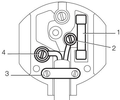
- Only fit 13 Amperes BS1363A approved plugs fitted with the correctly rated fuse (1).
- The cable wire colours, or a letter, will be marked at the connection points of most good quality plugs. Attach the wires to their respective
points in the plug (see below). Brown is for Live (L) (2) and Blue is for Neutral (N) (4).
- Before replacing the top cover of the mains plug ensure that the cable restraint (3) is holding the outer sheath of the cable firmly and that the two leads are correctly fixed at the terminals crews.

WARNING: NEVER use a light socket.
NEVER connect the live (L) or neutral (N) wires to the earth pin marked E or ( \frac{1}{\overline{\overline{\overline{\overline{\overline{\overline{\overline{\overline{\overline{\overline{\overline{\overline{\overline{\overline{\overline{\overline{\overline{\overline{\overline{\overline{\overline{\overline{\overline{\overline{\overline{\overline{\overline{\overline{\overline{\overline{\overline{\overline{\overline{\overline{\$\overline{\overline{\overline{\overline{\overline{\overline{\overline{\overline{\overline{\overline{\overline{\overline{\overline{\overline{\overline{\overline{\overline{\overline{\overline{\overline{\overline{\overline{\overline{\overline{\overline{\overline{\overline{\overline{\overline{\overline{\overline{\overline{\overline{\
Using an extension cable
An extension cord should not be used unless absolutely necessary. Use an approved extension cable suitable for the power input of your charger (see technical data). The minimum conductor size is 1 mm ^2 ; the maximum length is 30 m.
When using a cable reel, always unwind the cable completely.
ASSEMBLY AND ADJUSTMENTS

WARNING: Prior to assembly and adjustment, always remove the battery pack. Always switch off the tool before inserting or removing the battery pack.

WARNING: Use only DEWALT battery packs and chargers.
Inserting and removing the battery pack from the tool (fig. 2)

WARNING: To reduce the risk of serious personal injury, turn tool off and disconnect battery pack before making any adjustments or removing/installing attachments or accessories. An accidental start-up can cause injury.
TO INSTALL THE BATTERY PACK INTO THE TOOL HANDLE
- Align the base of the tool with the notch inside the tool's handle (fig. 2).
- Slide the battery pack firmly into the handle until you hear the lock snap into place.
TO REMOVE THE BATTERY PACK FROM THE TOOL
- Press the battery release buttons (h) and firmly pull the battery pack out of the tool handle.
- Insert battery pack into the charger as described in the charger section of this manual.
OPERATION
Instructions for use

WARNING: Always observe the safety instructions and applicable regulations.
Variable Speed Switch (fig. 1)
To turn the tool on, squeeze the trigger switch (a).
To turn the tool off, release the trigger switch. Your tool is equipped with a brake. The chuck will stop as soon as the trigger switch is fully released.
NOTE: Continuous use in variable speed range is not recommended. It may damage the switch and should be avoided.
Forward/Reverse Control Button (fig. 1)
A forward/reverse control button (b) determines the direction of the tool and also serves as a lock off button.
To select forward rotation, release the trigger switch and depress the forward/reverse control button on the right side of the tool.
To select reverse, depress the forward/reverse control button on the left side of the tool.
The center position of the control button locks the tool in the off position. When changing the position of the control button, be sure the trigger is released.
NOTE: The first time the tool is run after changing the direction of rotation, you may hear a click on start up. This is normal and does not indicate a problem.
Torque Adjustment Collar (fig. 1)
Your tool has an adjustable torque screwdriver mechanism for driving and removing a wide array of fastener shapes and sizes and in some models, a hammer mechanism for drilling into masonry. Circling
ENGLISH
the collar (c) are numbers, a drill bit symbol, and in some models, a hammer symbol. These numbers are used to set the clutch to deliver a torque range. The higher the number on the collar, the higher the torque and the larger the fastener which can be driven. To select any of the numbers, rotate until the desired number aligns with the arrow.
Dual Range Gearing (fig. 1)
The dual range feature of your driver/drill allows you to shift gears for greater versatility.
To select the low speed, high torque setting, turn the tool off and permit to stop. Slide the gear selector (d) forward (towards the chuck) as shown in Figure 1.
To select the high speed, low torque setting, turn the tool off and permit to stop. Slide the gear selector back (away from chuck).
NOTE: Do not change gears when the tool is running. If you are having trouble changing gears, make sure that the dual range gear selector is either completely pushed forward or completely pushed back.
Worklight (fig. 1)
There is a worklight (e) located just above the trigger switch (a). The worklight will be activated when the trigger switch is squeezed.
NOTE: The worklight is for lighting the immediate work surface and is not intended to be used as a flashlight.
Keyless Single Sleeve Chuck (fig. 1)
Your tool features a keyless chuck (f) with one rotating sleeve for one-handed operation of the chuck. To insert a drill bit or other accessory, follow these steps.
- Lock the trigger in the OFF position as previously described.
- Grasp the black sleeve of the chuck with one hand and use the other hand to secure the tool. Rotate the sleeve counterclockwise far enough to accept the desired accessory.
- Insert the accessory about 19 mm into the chuck and tighten securely by rotating the chuck sleeve clockwise with one hand while holding the tool with the other. Your tool is equipped with an automatic spindle lock mechanism. This allows you to open and close the chuck with one hand.
To release the accessory, repeat step 2 above.

WARNING: Do not attempt to tighten drill bits (or any other accessory) by gripping the front part of the chuck and turning the tool on. Damage to the chuck and personal injury may result. Always lock off trigger switch when changing accessories.
Be sure to tighten chuck with one hand on the chuck sleeve and one hand holding the tool for maximum tightness.
Drill Operation (fig. 4)

WARNING: To reduce the risk of serious personal injury, turn tool off and disconnect tool from power source before making any adjustments or removing/installing attachments or accessories.

WARNING: To reduce the risk of personal injury, ALWAYS ensure workpiece is anchored or clamped firmly. If drilling thin material, use a wood "back-up" block to prevent damage to the material.
- Use sharp drill bits only. For WOOD, use the low speed setting and twist drill bits, spade bits, power auger bits, or hole saws. For METAL, use the low speed setting and steel twist drill bits or hole saws. For MASONRY, such as brick, cement, cinder block, etc., use carbide-tipped bits rated for percussion drilling. Use low speed for bits greater than 10 mm.
- Always apply pressure in a straight line with the bit. Use enough pressure to keep drill biting, but do not push hard enough to stall the motor or deflect the bit.
- Hold tool firmly with both hands to control the twisting action of the drill. If model is not equipped with side handle, grip drill with one hand on the handle and one hand on the battery pack.

CAUTION: Drill may stall if overloaded causing a sudden twist. Always expect the stall. Grip the drill firmly to control the twisting action and avoid injury.
-
IF DRILL STALLS, it is usually because it is being overloaded or improperly used. RELEASE TRIGGER IMMEDIATELY, remove drill bit from work, and determine cause of stalling. DO NOT CLICK TRIGGER ON AND OFF IN AN ATTEMPT TO START A STALLED DRILL — THIS CAN DAMAGE THE DRILL.
-
To minimize stalling or breaking through the material, reduce pressure on drill and ease the bit through the last fractional part of the hole.
- Keep the motor running when pulling the bit back out of a drilled hole. This will help prevent jamming.
- With variable speed drills there is no need to center punch the point to be drilled. Use a slow speed to start the hole and accelerate by squeezing the trigger harder when the hole is deep enough to drill without the bit skipping out.
Hammerdrill Operation (fig. 5)
- Turn the collar (c) to the hammerdrill symbol.
- Select the high speed setting by sliding the selector back (away from the chuck).
IMPORTANT: Use carbide-tipped or masonry bits only.
- Drill with just enough force on the hammer to keep it from bouncing excessively or "rising" off the bit. Too much force will cause slower drilling speeds, overheating and lower drilling rate.
- Drill straight, keeping the bit at a right angle to the work. Do not exert side pressure on the bit when drilling as this will cause clogging of the bit flutes and a slower drilling speed.
- When drilling deep holes, if the hammer speed starts to drop off, pull the bit partially out of the hole with tool still running to help clear debris from the hole.
NOTE: A smooth, even flow of dust from the hole indicates proper drilling rate.
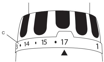
Screwdriver Operation (fig. 6)
- Select the desired speed/torque range using the dual range gear selector to match the speed and torque of the planned operation.
- Turn the torque adjustment collar to the desired position. Lower numbers indicate lower torque settings; higher numbers indicate higher torque settings.
- Insert the desired fastener accessory into the chuck as you would any drill bit.
- Make some practice runs in scrap or on unseen areas to determine the proper position of the clutch collar.
- Always start with lower torque settings, then advance to higher torque settings to avoid damage to the workpiece or fastener.
MAINTENANCE
Your DEWALT power tool has been designed to operate over a long period of time with a minimum of maintenance. Continuous satisfactory operation depends upon proper tool care and regular cleaning.

WARNING: To reduce the risk of injury, turn unit off and disconnect tool from power source before installing and removing accessories, before making any adjustments or removing/installing attachments or accessories.

Lubrication
Your power tool requires no additional lubrication.

Cleaning

WARNING: Blow dirt and dust out of the main housing with dry air as often as dirt is seen collecting in and around the air vents. Wear approved eye protection and approved dust mask when performing this procedure.

WARNING: Never use solvents or other harsh chemicals for cleaning the non-metallic parts of the tool. These chemicals may weaken the materials used in these parts. Use a cloth dampened only with water and mild soap. Never let any liquid get inside the tool; never immerse any part of the tool into a liquid.
CHARGER CLEANING INSTRUCTIONS

WARNING: Shock hazard. Disconnect the charger from the AC outlet before cleaning. Dirt and grease may be removed from the exterior of the charger using a cloth or soft non-metallic brush. Do not use water or any cleaning solutions.
Optional accessories

WARNING: Since accessories, other than those offered by DEWALT, have not been tested with this product, use of such accessories with this tool could be hazardous. To reduce the risk of
ENGLISH
injury, only DEWALT, recommended accessories should be used with this product.
Consult your dealer for further information on the appropriate accessories.
Protecting the environment

Separate collection. This product must not be disposed of with normal household waste.

Should you find one day that your DEWALT product needs replacement, or if it is of no further use to you, do not dispose of it with household waste. Make this product available for separate collection.

Separate collection of used products and packaging allows materials to be recycled and used again. Re-use of recycled materials helps prevent environmental pollution and reduces the demand for raw materials.
Local regulations may provide for separate collection of electrical products from the household, at municipal waste sites or by the retailer when you purchase a new product.
DEWALT provides a facility for the collection and recycling of DEWALT products once they have reached the end of their working life. To take advantage of this service please return your product to any authorised repair agent who will collect them on our behalf.
You can check the location of your nearest authorised repair agent by contacting your local DEWALT office at the address indicated in this manual. Alternatively, a list of authorised DEWALT repair agents and full details of our after-sales service and contacts are available on the Internet at:
www.2helpU.com.

Rechargeable Battery Pack
This long life battery pack must be recharged when it fails to produce sufficient power on jobs which were easily done before. At the end of its technical life, discard it with due care for our environment:
- Run the battery pack down completely, then remove it from the tool.
- Li-Ion, NiCd and NiMH cells are recyclable. Take them to your dealer or a local recycling station. The collected battery packs will be recycled or disposed of properly.
GUARANTEE
• 30 DAY NO RISK SATISFACTION GUARANTEE •
If you are not completely satisfied with the performance of your DEWALT tool, simply return it within 30 days, complete as purchased, to the point of purchase, for a full refund or exchange. Proof of purchase must be produced.
• ONE YEAR FREE SERVICE CONTRACT •
If you need maintenance or service for your DEWALT tool, in the 12 months following purchase, it will be undertaken free of charge at an authorized DEWALT repair agent. Proof of purchase must be produced. Includes labour and spare parts for Power Tools. Excludes accessories.
• ONE YEAR FULL WARRANTY •
If your DEWALT product becomes defective due to faulty materials or workmanship within 12 months from the date of purchase, we guarantee to replace all defective parts free of charge or, at our discretion, replace the unit free of charge provided that:
- The product has not been misused.
- Repairs have not been attempted by unauthorized persons.
- Proof of purchase date is produced. This guarantee is offered as an extra benefit and is additional to consumers statutory rights.
For the location of your nearest authorized DEWALT repair agent, please use the appropriate telephone number on the back of this manual. Alternatively, a list of authorized DEWALT repair agents and full details on our after-sales service are available on the Internet at www.2helpU.com.
DC720, DC721, DC722, DC730, DC731, DC732, DC742, DC743 TALADROS/ATORNILLADORES COMPACTOS INALÁMBRICOS DC725, DC727, DC735, DC737, DC745 TALADRO/ATORNILLADOR/ TALADRO PERCUTOR COMPACTO INALÁMBRICO
¡Enhorabuena!
DC720, DC721, DC722, DC725, DC727, DC730, DC731, DC732, DC735, DC737, DC742, DC743, DC745
DC720, DC721, DC722, DC725, DC727, DC730, DC731, DC732, DC735, DC737, DC742, DC743, DC745
NiMH ^+ Charges NiMH and NiCd battery packs. NiCd

Li Ion Charge les blocs-piles Li-Ion.

Bloc-piles rechargeable
DC720, DC721, DC722, DC725, DC727, DC730, DC731, DC732, DC735, DC737, DC742, DC743, DC745
DC720, DC721, DC722, DC730, DC731, DC732, DC742, DC743 DRAADLOZE COMPACTE KLOPBOREN DC725, DC727, DC735, DC737, DC745 DRAADLOZE COMPACTE KLOPBOOR/HAMERBOOR
Gefeliciteerd!
DC720, DC721, DC722, DC725, DC727, DC730, DC731, DC732, DC735, DC737, DC742, DC743, DC745
DC720, DC721, DC722, DC725, DC727, DC730, DC731, DC732, DC735, DC737, DC742, DC743, DC745
1) SIKKERHET PÅ ARBEIDSPLASSEN
DC720, DC721, DC722, DC725, DC727, DC730, DC731, DC732, DC735, DC737, DC742, DC743, DC745
A DEWALT declara que estes produtos descritos em “dados técnicos” foram concebidos em conformidade com a norma: 98/37/CEE (até 28 de Dez. de 2009), 2006/42/CE (a partir de 29 de Dez. de 2009), 2004/108/EC, 2006/95/CE, EN 55014-1, EN 55014-2, EN 60745-1, EN 60745-2-1, EN 60745-2-2.
DC720, DC721, DC722, DC730, DC731, DC732, DC742, DC743
LADATTAVA PORA/RUUVINVÄÄNTIMET
DC725, DC727, DC735, DC737, DC745
LADATTAVA PORA/RUUVINVÄÄNNIN/PORAVASARA
Onnittelut!
DC720, DC721, DC722, DC725, DC727, DC730, DC731, DC732, DC735, DC737, DC742, DC743, DC745
Vice President Engineering and Product Development
DEWALT, Richard-Klinger-Strase 11, D-65510, Idstein, Saksa
16.09.2007

DC720, DC721, DC722, DC730, DC731, DC732, DC742, DC743 SLADDLÖS KOMPAKT BORRMASKIN/SKRUVDRAGARE DC725, DC727, DC735, DC737, DC745 SLADDLÖS KOMPAKT BORRMASKIN/SLAGBORR
Gratulerar!
DC720, DC721, DC722, DC725, DC727, DC730, DC731, DC732, DC735, DC737, DC742, DC743, DC745
DC720, DC721, DC722, DC730, DC731, DC732, DC742, DC743 KABLOSUZ KOMPAKT MATKAP/TORNAVIDALAR DC725, DC727, DC735, DC737, DC745 KABLOSUZ KOMPAKT MATKAP/TORNAVIDA/DARBELI MATKAP
Tebrikler!
DC720, DC721, DC722, DC725, DC727, DC730, DC731, DC732, DC735, DC737, DC742, DC743, DC745
NIKEL KADMIYUM (NiCd) VEYA NIKEL METAL HIDRIT (NiMH) İÇIN ÖZEL GÜVENLIK TALIMATLARI
DC720, DC721, DC722, DC725, DC727, DC730, DC731, DC732, DC735, DC737, DC742, DC743, DC745