
D27300 - Planer and Jointer DEWALT - Free user manual and instructions
Find the device manual for free D27300 DEWALT in PDF.

| Product type | Planer/jointer |
| Brand | DEWALT |
| Model | D27300 |
| Voltage | 230-240 V (single phase) / 400 V (three phase for D27300T) |
| Power consumption | 2100 W (D27300) / 3000 W (D27300T) |
| Useful power | 1650 W (D27300) / 2280 W (D27300T) |
| No-load speed | 6200 min⁻¹ |
| Feed speed | 5 m/min |
| Max. cutting height | 160 mm |
| Max. cutting width | 260 mm |
| Max. cutting depth (planing) | 2.5 mm |
| Max. cutting depth (thicknessing) | 3 mm |
| Blade size | 20 mm |
| Weight | 54 kg |
| Sound pressure level | 99 dB(A) |
| Sound power level | 108 dB(A) |
| Recommended fuses | 16 A (230 V machines) |
| Package contents | Assembled planer, protective device, chip collector, fence, push stick, Allen keys (2.5/4/5/6 mm), 13/10 mm wrench, adjustment gauge, elevating handle, clamping handles, feet, wheels, instruction manual, exploded drawing |
| Warranty | 1 year (manufacturing defects), 30 days satisfaction, 1 year free maintenance |
| Safety | Emergency stop (hinged plate), overload protection, lockable, circuit breaker switch |
| Maintenance | Blade change (always in pairs), sharpening at 42° (max 3 mm material), regular cleaning of tables and ventilation slots, lubrication not required |
| Spare parts available | Replacement blades DE7330 |
Frequently Asked Questions - D27300 DEWALT
User questions about D27300 DEWALT
0 question about this device. Answer the ones you know or ask your own.
Ask a new question about this device
Download the instructions for your Planer and Jointer in PDF format for free! Find your manual D27300 - DEWALT and take your electronic device back in hand. On this page are published all the documents necessary for the use of your device. D27300 by DEWALT.
USER MANUAL D27300 DEWALT
A2
natural_image
Technical line drawing of an internal combustion chamber with cooling fans and exhaust pipes (no text or labels)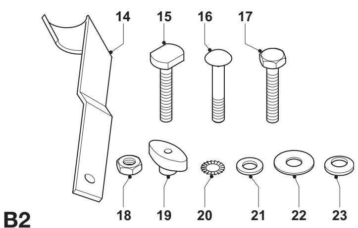
C1
D1
C2
D2
D3
E1
E2
E3
natural_image
Technical line drawing of a mechanical assembly with no visible text or symbols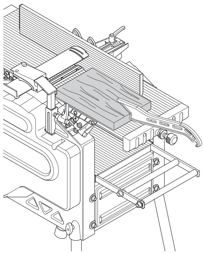
natural_image
Technical line drawing of a mechanical assembly with no visible text or symbolsN1
N2
natural_image
Technical line drawing of a mechanical assembly with no visible text or symbols01
natural_image
Technical line drawing of a mechanical assembly with no visible text or symbols02
natural_image
Simple diagram showing three gray circles on a hatched surface, no text or symbols presentP1
natural_image
Pure geometric shape with diagonal hatching and a curved boundary (no text or symbols)P2
natural_image
3D illustration of a curved, grainy wooden plank with visible grain patterns (no text or symbols)P3
P4
natural_image
Technical line drawing of a quadrupedal robotic device with labeled components (no text or symbols beyond labels)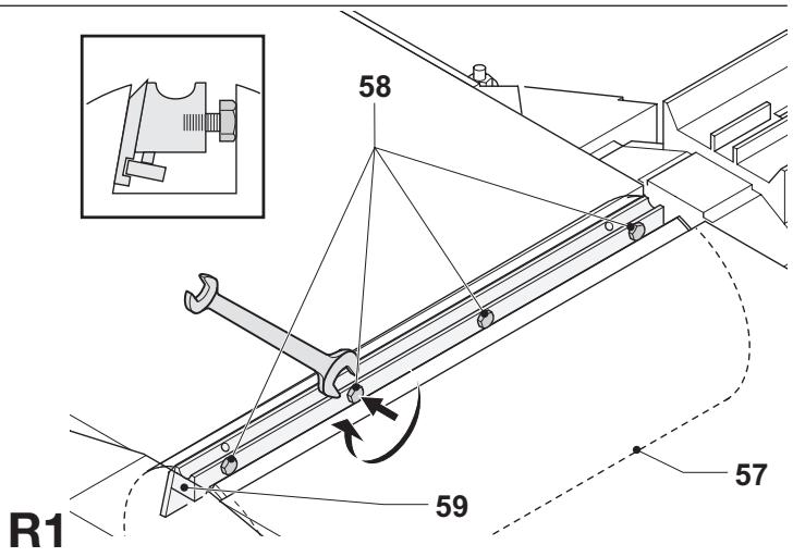
TYKKELSESH∅VL D27300/D27300T
Tillykke!
Product and Safety GmbH (TRPS)
Am Grauen Stein 1
D-51105 Köln
Germany
| Cert. No. |
| 21111827 001 |
Product and Safety GmbH (TRPS)
Am Grauen Stein 1
D-51105 Köln
Germany
You have chosen a DeWALT tool. Years of experience, thorough product development and innovation make DeWALT one of the most reliable partners for professional power tool users.
Technical data
| D27300 | D27300T | ||
| Voltage | V | 230 – 240 | 400 |
| Power input | W | 2,100 | 3,000 |
| Power output | W | 1,650 | 2,280 |
| No-load speed | min^-1 | 6,200 | 6,200 |
| Feed speed | m/min | 5 | 5 |
| Cutting height (max.) | mm | 160 | 160 |
| Max. cutting width (max) | mm | 260 | 260 |
| Max. cutting depth | |||
| Planing mode | mm | 2.5 | 2.5 |
| Thicknessing mode | mm | 3 | 3 |
| Blade size | mm | 20 | 20 |
| Weight | kg | 54 | 54 |
| Fuses: | ||
| Europe | 230 V tools | 16 Amperes, mains |
| 400 V tools | 16 Amperes, per phase | |
The following symbols are used throughout this manual:

Denotes risk of personal injury, loss of life or damage to the tool in case of non-observance of the instructions in this manual.

Denotes risk of electric shock.

Sharp edges.
EC-Declaration of conformity

D27300/D27300T
DeWALT declares that these power tools have been designed in compliance with: 98/37/EEC, 89/336/EEC, 73/23/EEC, EN 55014-2, EN 55014, EN 61000-3-2, EN 61000-3-3 & EN 61029.
For more information, please contact DEWALT at the address below or refer to the back of the manual.
| D27300 | D27300T | ||
| L_pA (sound pressure) | dB(A)* | 99 | 99 |
| L_WA (acoustic power) | dB(A) | 108 | 108 |
* at the operator's ear
Director Engineering and Product Development
Horst Großmann
$$ \chi . f o p s m a n $$
D-65510, Idstein, Germany
TÜV Rheinland
Product and Safety GmbH (TRPS)
Am Grauen Stein 1
D-51105 Köln
Germany
| Cert. No. | |
| 21111827 001 |
Safety instructions
When using stationary power tools, always observe the safety regulations applicable in your country to reduce the risk of fire, electric shock and personal injury.
Read all of this manual carefully before operating the tool.
Save this manual for future reference.
General
1 Keep work area clean
Cluttered areas and benches can cause accidents.
2 Consider work area environment
Do not expose the tool to rain. Do not use the tool in damp or wet conditions. Keep the work area well lit (250 - 300 Lux). Do not use the tool where there is a risk of causing fire or explosion, e.g. in the presence of flammable liquids and gases.
3 Keep children away
Do not allow children, visitors or animals to come near the work area or to touch the tool or the mains cable.
4 Dress properly
Do not wear loose clothing or jewellery, as these can be caught in moving parts. Wear protective hair covering to keep long hair out of the way. When working outdoors, preferably wear suitable gloves and non-slip footwear.
5 Personal protection
Always use safety glasses. Use a face or dust mask whenever the operations may produce dust or flying particles. If these particles might be considerably hot, also wear a heat-resistant apron. Wear ear protection at all times. Wear a safety helmet at all times.
6 Guard against electric shock
Prevent body contact with earthed or surfaces (e.g. pipes, radiators, cookers and refrigerators). When using the tool under extreme conditions (e.g. high humidity, when metal swarf is being produced, etc.), electric safety can be improved by inserting an isolating transformer or a (FI) earth-leakage circuit-breaker.
7 Do not overreach
Keep proper footing and balance at all times.
8 Stay alert
Watch what you are doing. Use common sense. Do not operate the tool when you are tired.
9 Secure workpiece
Use clamps or a vice to hold the workpiece. It is safer and it frees both hands to operate the tool.
10 Connect dust extraction equipment
If devices are provided for the connection of dust extraction and collection facilities, ensure that these are connected and properly used.
11 Remove adjusting keys and wrenches
Always check that adjusting keys and wrenches are removed from the tool before operating the tool.
12 Extension cables
Before use, inspect the extension cable and replace if damaged. When using the tool outdoors, only use extension cables intended for outdoor use and marked accordingly.
13 Use appropriate tool
The intended use is described in this instruction manual. Do not force small tools or attachments to do the job of a heavy-duty tool. The tool will do the job better and safer at the rate for which it was intended. Do not force the tool.
Warning! The use of any accessory or attachment or performance of any operation with this tool other than those recommended in this instruction manual may present a risk of personal injury.
14 Check for damaged parts
Before use, carefully check the tool and mains cable for damage. Check for misalignment and seizure of moving parts, breakage of parts, damage to guards and switches and any other conditions that may affect its operation.
Ensure that the tool will operate properly and perform its intended function. Do not use the tool if any part is damaged or defective. Do not use the tool if the switch does not turn it on and off. Have any damaged or defective parts replaced by an authorised DEWALT repair agent. Never attempt any repairs yourself.
15 Unplug tool
Switch off and wait for the tool to come to a complete standstill before leaving it unattended. Unplug the tool when not in use, before changing any parts of the tools, accessories or attachments and before servicing.
16 Avoid unintentional starting
Be sure that the tool is switched off before plugging in.
17 Do not abuse cord
Never pull the cord to disconnect from the socket. Keep the cord away from heat, oil and sharp edges.
18 Store idle tools
When not in use, tools must be stored in a dry place and locked up securely, out of reach of children.
19 Maintain tools with care
Keep the tools in good condition and clean for better and safer performance. Follow the instructions for maintenance and changing accessories. Keep all handles and switches dry, clean and free from oil and grease.
20 Repairs
This tool is in accordance with the relevant safety regulations. Have your tool repaired by an authorised DEWALT repair agent. Repairs should only be carried out by qualified persons using original spare parts; otherwise this may result in considerable danger to the user.
Additional safety rules for thickness planers
- It is advisable to wear safety goggles when operating.
- Never run the machine without all guards in place and in perfect working condition.
- Do not use the machine without the fence in position. Make sure that the lower edge of the fence touches the upper table top.
- Warning! The infeed and outfeed table were accurately adjusted at the factory. Never change the setting of the tables yourself.
- Use only cutting blades recommended by the manufacturer.
- Always use sharp blades of the correct type designed for the workpiece.
- Do not use the machine for working any material other than soft or hard wood.
- Never cut recesses, tenons or moulds.
- Never carry out stopped work (i.e. cuts that do not involve working over the full length of the workpiece).
- Avoid working badly bowed wood providing inadequate contact with the in-feed table.
- Before use, check that the kickback and feed spindles are functioning properly.
- Remove all nails and metal objects from the workpiece before starting work.
- In the planing mode, make sure the upper blade guard is adjusted to provide optimum screening.
- Ensure that the elevating handle is out of the feed area.
- When working long pieces, use a suitable roller table on both sides of the machine adjusted to the height of the tables.
- Keep your hands well clear off the blades.
- In the thickening mode, never plane material shorter than 305 mm.
- In the planing mode, use a push stick at all times.
- Keep the push stick in its place when not in use.
Residual risks
The following risks are inherent to the use of planers:
In spite of the application of the relevant safety regulations and the implementation of safety devices, certain residual risks cannot be avoided.
These are:
- Risk of accidents caused by the uncovered parts of the rotating blade.
- Risk of injury when changing the blade.
- Risk of squeezing fingers when opening the guards.
- Health hazards caused by breathing dust developed when planing wood, especially oak, beech and MDF.
Labels on tool
The following pictograms are shown on the tool:

Read the instruction manual before use
When using the machine in the thicknessing mode, be aware of the direction of feed. Never use the machine without shavings collector in position.
When using the machine in the planing mode, be aware of the direction of feed. Never use the machine without shavings collector in position.

Make sure that the cutting blades are properly adjusted. Do not allow the blades to protrude from the cutterhead by more than 1.1 mm
Package contents
The package contains:
1 Partly assembled thickness planer
1 Guard
1 Shavings collector
1 Box containing:
1 Fence
1 Push stick
1 Bag containing:
1 Allen key 2.5 mm
1 Allen key 4 mm
1 Allen key 5 mm
1 Allen key 6 mm
1 Spanner 13/10 mm
1 Adjustment gauge
1 Elevating handle
2 Clamp handles
4 Rubber feet
1 M8 coach bolt
4 M8 nuts
4 D8 toothed washers
1 D8 flat washer
1 Box containing:
4 Legs
2 Wheels
2 Wheel brackets
1 Bag containing:
2 Wheel axles
4 M8 coach bolts
2 M8 hex head bolts
4 M8 nuts
4 Wing nuts
4 D8 flat washers
6 D8 Belleville washers
1 Instruction manual
1 Exploded drawing
- Check for damage to the tool, parts or accessories which may have occurred during transport.
- Take the time to thoroughly read and understand this manual prior to operation.
Description (fig. A1 & A2)
Your D27300/D27300T thickness planer has been designed for professional planing of wood.
Fig. A1
1 On/off switch
2 Elevating handle
3 Lower table
4 Shavings collector
5 Scale lower table
6 Push stick
7 Fence clamp handle
8 Fence
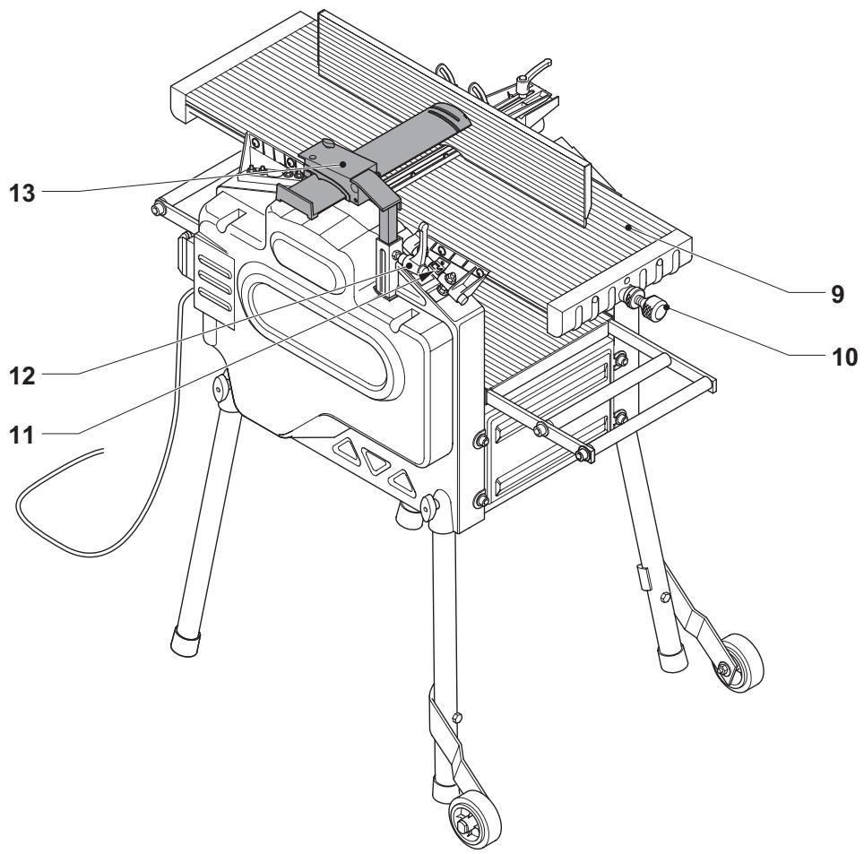
Fig. A2
9 Upper table
10 Planning depth adjustment knob
11 Scale upper table
12 Guard clamp handle
13 Guard
Electrical safety
The electric motor has been designed for one voltage only. Always check that the power supply corresponds to the voltage on the rating plate.
Using an extension cable
If an extension cable is required, use an approved extension cable suitable for the power input of this machine (see technical data). The minimum conductor size is 1.5 mm^2 .
When using a cable reel, always unwind the cable completely.
Also refer to the table below.
| Conductor size (mm2) | Cable rating (Amperes) | ||||||
| 1.50 | 15 | ||||||
| 2.50 | 20 | ||||||
| 4.00 | 25 | ||||||
| Cable length (m) | |||||||
| 7.515 25 | 30 | 45 | 60 | ||||
| Voltage | Amperes | Cable rating (Amperes) | |||||
| 230 | 0 - 2.0 | 6 | 6 | 6 | 6 | 6 | 6 |
| 2.1 - 3.4 | 6 | 6 | 6 | 6 | 6 | 6 | |
| 3.5 - 5.0 | 6 | 6 | 6 | 6 | 10 | 15 | |
| 5.1 - 7.0 | 10 | 10 | 10 | 10 | 15 | 15 | |
| 7.1 - 12.0 | 15 | 15 | 15 | 15 | 20 | 20 | |
| 12.1 - 20.0 | 20 | 20 | 20 | 20 | 25 | - | |
Three-phase machines should be wired directly into the mains by a suitably qualified electrician.
Voltage drops
Inrush currents cause short-time voltage drops. Under unfavourable power supply conditions, other equipment may be affected.
If the system impedance of the power supply is lower than 0.25 , disturbances are unlikely to occur.
Assembly

Prior to assembly always unplug the tool.
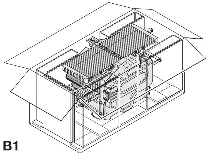
Unpacking the machine and its parts (fig. B1)
- Remove the loose packaging material from the box.
- Lift the machine out of the box.
- Remove the parts box from the interior of the machine.
- Remove any remaining packing material from the machine.
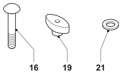
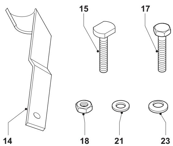
Identifying the hardware parts (fig. B2)
We recommend that you unpack and sort all hardware parts.
14 Wheel bracket
15 Wheel axle
16 M8 coach bolt
17 M8 hex head bolt
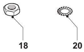
18 M8 nut
19 Wing nut
20 D8 toothed washer
21 D8 flat washer
22 D8 flat washer
23 D8 Belleville washer
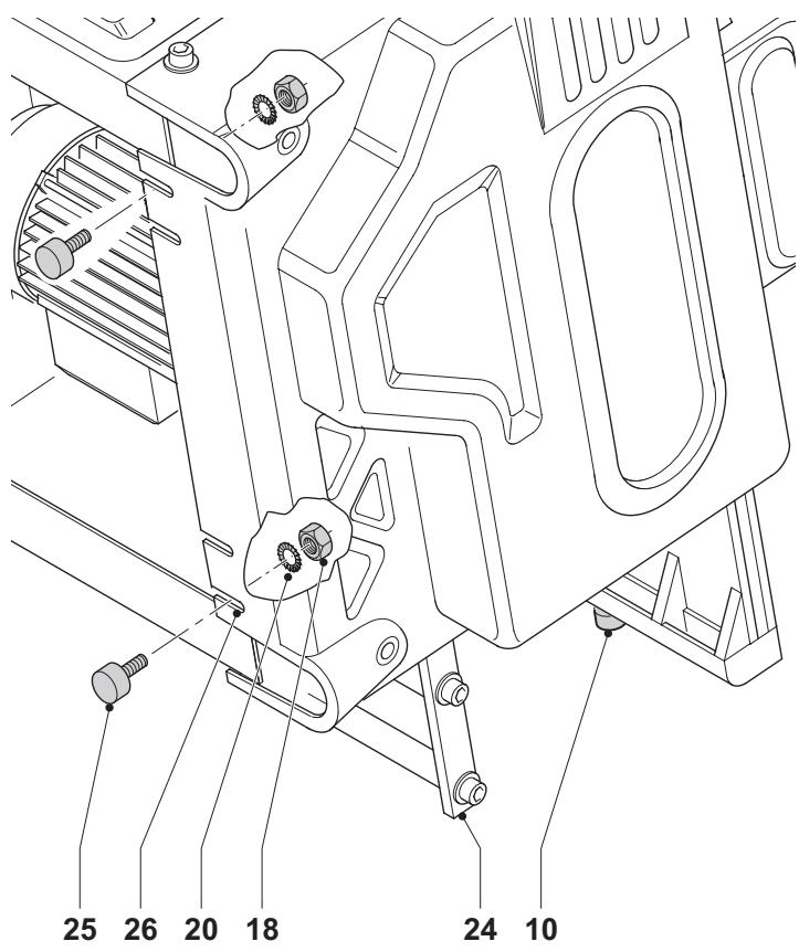
Mounting the feet (fig. C1 & C2)
With the feet mounted, the machine is suitable for placement on a workbench. To ensure a safe operation, the machine has to be fixed to the workbench. Required hardware parts: 4 nuts (18), 4 toothed washers (20) (fig. C1).
- Turn the machine on its side with the thicknessing outfeed frame (24) resting on the floor (fig. C2).

Take care to avoid that the planing dept adjustment knob (10) hits the floor.
- Insert a foot (25) into each of the outer notches (26) located in the bottom of the machine housing.
- Place a toothed washer (20) and a nut (18) onto the threaded end of the feet.
- Tighten the nuts.
- Turn the machine straight up.
- Fix the machine to the workbench.
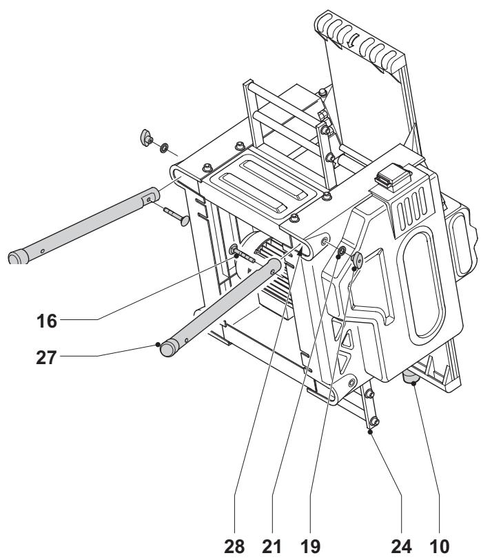
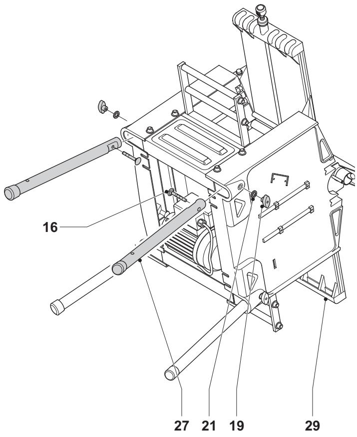
Mounting the legs (fig. D1 - D3)
With the legs mounted, the machine is suitable for stand-alone placement. Required hardware parts: 4 coach bolts (16), 4 wing nuts (19), 4 flat washers (21) (fig D1).
- Turn the machine on its side with the thicknessing outfeed frame (24) resting on the floor (fig. D2).

Take care to avoid that the planing dept adjustment knob (10) hits the floor.
- Insert a leg (27) into each of the top holes (28) located at the edges in the bottom of the machine housing.
- Pass a coach bolt (16) through the holes in the legs and the machine housing.
- Place a flat washer (21) and a wing nut (19) onto the bolts.
- Tighten the wing nuts.
- Turn the machine on its side with the planing outfeed table (29) resting on the floor (fig. D3).
- Repeat as for the other feet.
- Mount the castor wheels as described below.
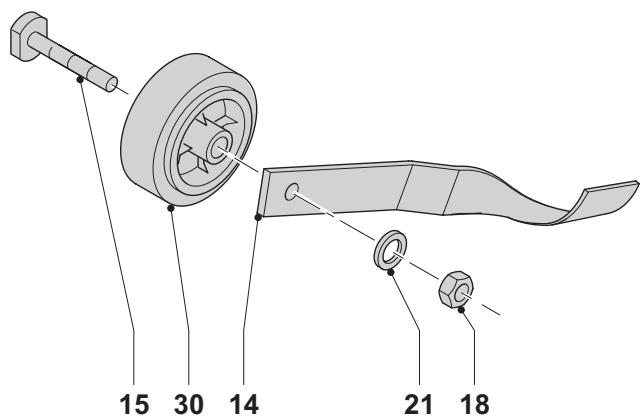
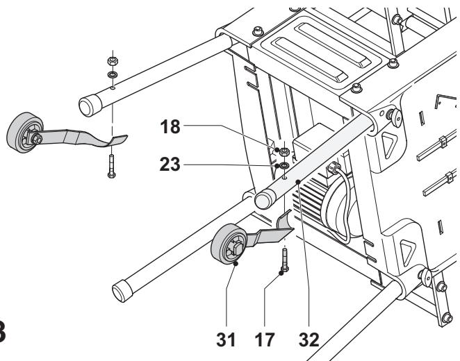
Mounting the castor wheels (fig. E1 - E3)
Required hardware parts: 2 wheel brackets (14), 2 wheel axles (15), 2 bolts (17), 4 nuts (18), 2 flat washers (21), 2 Belleville washers (23) (fig. E1).
- Align each wheel (30) with a bracket (14) and pass a wheel axle (15) through the holes of each assembly (fig. E2).
- Place a flat washer (21) and a nut (18) onto the threaded end of the axles.
- Tighten the nuts.
- Mount a wheel assembly (31) to each of the upper legs (32) using a hex head bolt (17), Belleville washer (23) and nut (18) (fig. E3).
- Tighten the nuts.
- Turn the machine straight up.
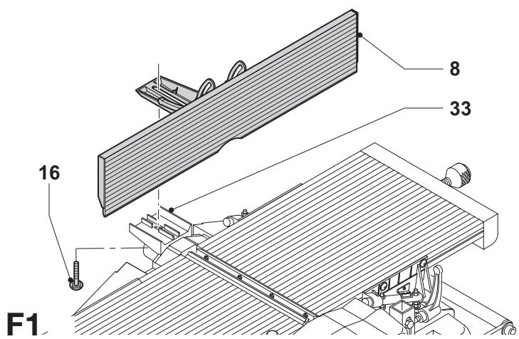
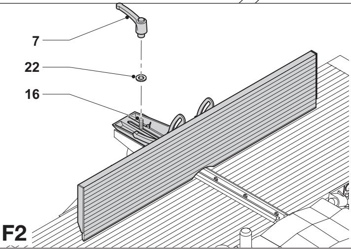
Mounting the fence (fig. F1 & F2)
- Place the fence (8) onto the fence holder (33) (fig. F1).
- Pass a coach bolt (16) from underneath through the holder and the fence.
- Place a flat washer (22) onto the bolt (16) (fig. F2).
- Fit the clamp handle (7) onto the bolt (16).
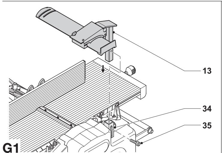
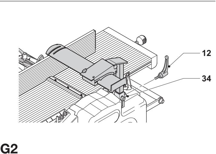
Mounting the guard (fig. G1 & G2)
- Insert the guard (13) into the guard column (34) (fig. G1).
- Locate the guard by fitting the lock screw (35).
- Fit the clamp handle (12) to the column (34) (fig. G2).
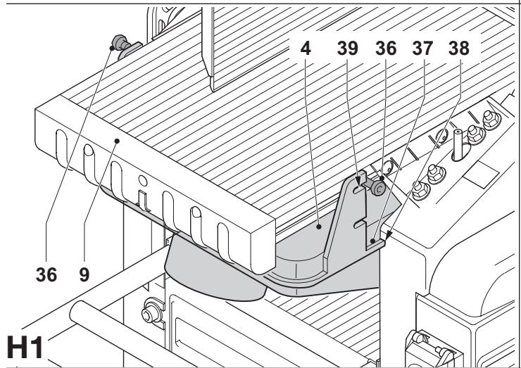
Mounting the shavings collector (fig. H1 & H2)
When using the machine in planing mode, the shavings collector has to be mounted underneath the upper table. When using the machine in thickening mode, the shavings collector has to be mounted on top of the upper table.
Planing mode (fig. H1)
- Loosen the screws (36) a few turns to allow the shavings collector to pass behind the head of the screws.
- Present the edges (37) on each side of the shavings collector to the grooves (38).
- Slide the shavings collector (4) underneath the upper table (9), until the recesses (39) locate behind the screws.
- Fix the shavings collector by tightening the screws.
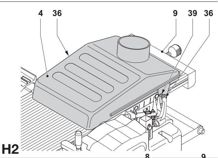
Thicknessing mode (fig. H2)
- Loosen the screws (36) a few turns to allow the shavings collector to pass behind the head of the screws.
- Place the shavings collector (4) upside over the upper table top (9).
- Slide the shavings collector (4) along the upper table (9), until the recesses (39) locate behind the screws.
- Fix the shavings collector by tightening the screws.
Adjustment

Prior to adjustment always unplug the tool.
Adjusting the fence (fig. I1 - I3)
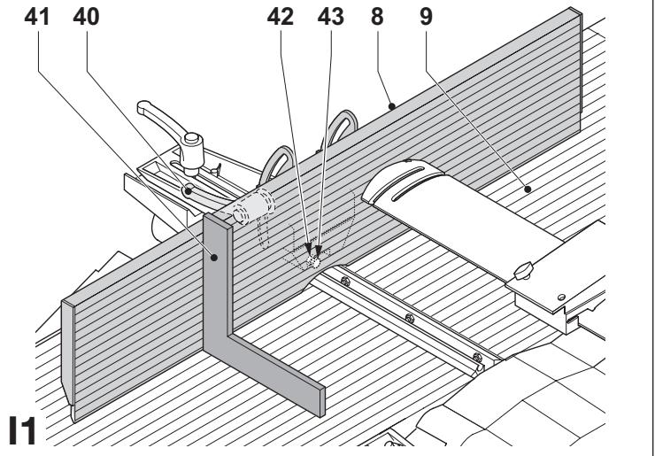
Adjusting the right angle (fig. I1)
The fence has an adjustable stop at for easy right angle adjustment.
- Loosen the angle clamp handle (40).
- Press the fence straight up to ensure it is fully vertical and tighten the angle clamp handle.
- Place a set square (41) on the table and up against the fence (8).
- If adjustment is required, proceed as follows:
- Loosen the nut (42) a few turns and turn the vertical position adjustment stop screw (43) in or out until the fence is at 90^ to the table as measured with the square.
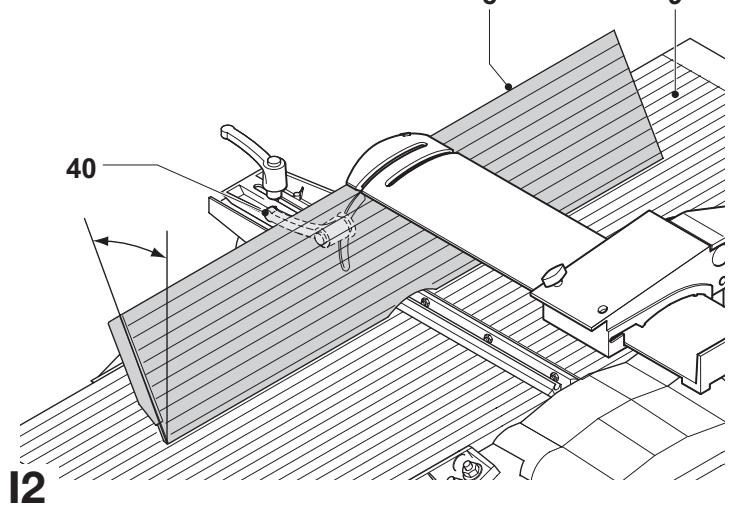
Adjusting the chamfering angle (fig. 12)
- Loosen the angle clamp handle (40).
- Move the fence (8) along its longitudinal axle to achieve the required angle.
- Make sure that the lower edge of the fence touches the upper table top (9).
- Tighten the angle clamp handle.
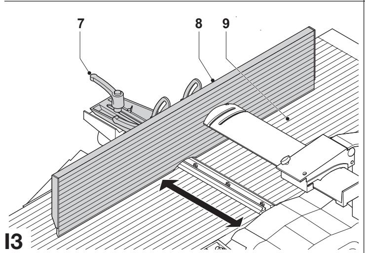
Adjusting the planing width (fig. 13)
- Loosen the fence clamp handle (7).
- Move the fence (8) across the upper table (9) to achieve the required width.
- Tighten the fence clamp handle.
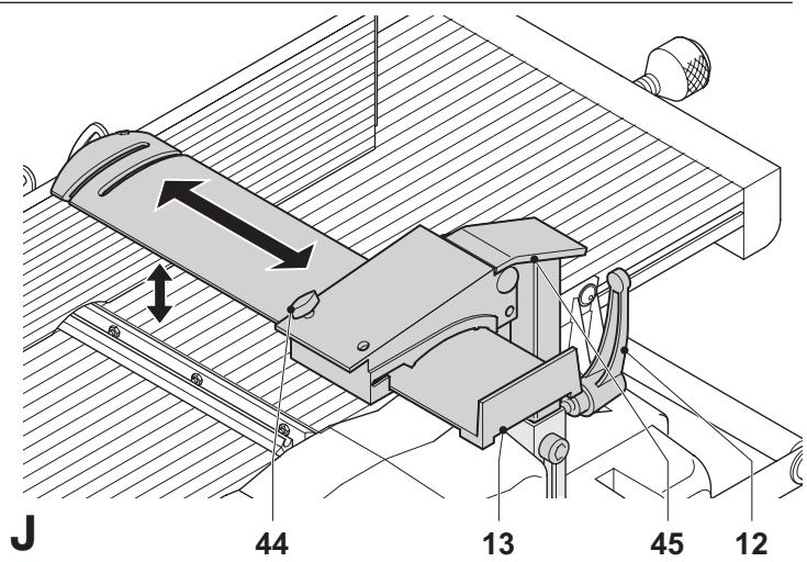
Adjusting the guard (fig. J)
The guard can be adjusted to any fixed position above the table to provide optimum screening.

Always make sure to adjust the guard to the planing width and the height of the workpiece.
To adjust the width:
- Loosen the lock knob (44).
- Move the guard (13) to the required width.
- Tighten the adjustment knob.
To adjust the height:
- Loosen the clamp handle (12).
- Move the guard bracket (45) to the required height.
- Tighten the clamp handle.
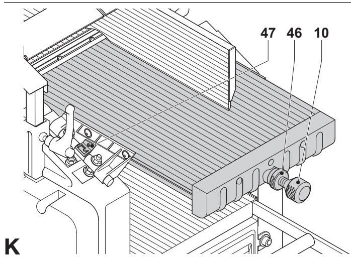
Adjusting the depth of cut (fig. K, L1 & L2)
Planing mode (fig. K)
- Loosen the locking ring (46).
- Take hold of the depth adjustment knob (10) and adjust the depth of cut using the scale (47).
- Turn clockwise to decrease the cutting depth.
- Turn counterclockwise to increase the cutting depth.
- Tighten the locking ring.
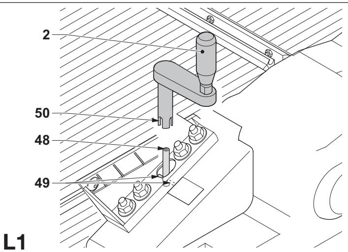
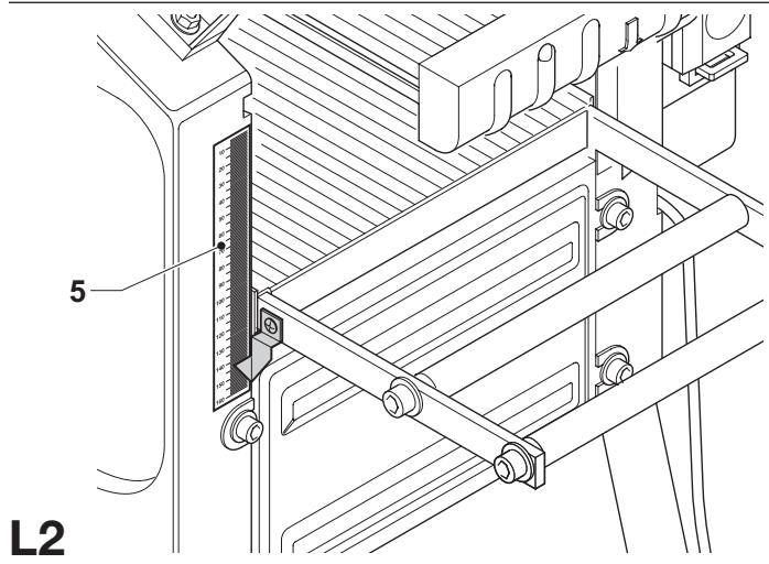
Thicknessing mode (fig. L1 & L2)
- Place the elevating handle (2) onto the elevating shaft end (48). Rotate the handle until shaft pin (49) engages in the slot (50) (fig. L1).
• Take hold of the elevating handle (3) and adjust the depth of cut. - Turn clockwise to decrease the cutting depth.
- Turn counterclockwise to increase the cutting depth.
- Read the finished thickness of your workpiece on the depth adjustment scale (5) (fig. L2).
Instructions for use

• Always observe the safety instructions and applicable regulations.
- Make sure there is sufficient space for the workpiece at the outfeed side.
- Allow the motor to reach full speed before feeding the workpiece. The workpiece should not be in contact with the cutterhead when switching on.
The attention of UK users is drawn to the „woodworking machines regulations 1974“ and any subsequent amendments.
Prior to operation:
- Remove all foreign objects. Do not plane wood with loose knots. Do not plane wood that is severely knotted or warped.
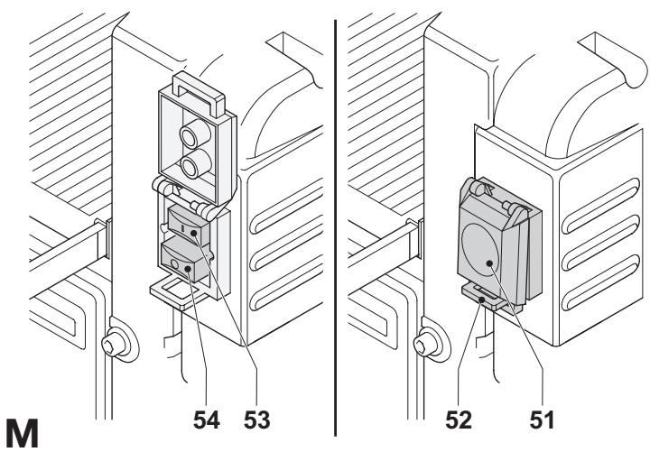
Switching on and off (fig. M)
The on/off switch offers multiple advantages:
- no-volt release function: should the power be shut off for some reason, the switch has to be deliberately reactivated.
- motor overload protection device: in case of motor overload, the power supply to the motor will be cut off. If this happens, let the motor to cool for 2 minutes and then press the green start button.
- extra safety: the hinged safety enclosure plate (51) can be locked by passing a padlock through the hasp (52). The plate also serves as an „easy to locate“ emergency stop button as pressure on the front of the plate will depress the stop button.
- To switch the machine on, press the green start button (53).
- To switch the machine off, press the red stop button (54).

Always switch off the machine when work is finished and before unplugging.
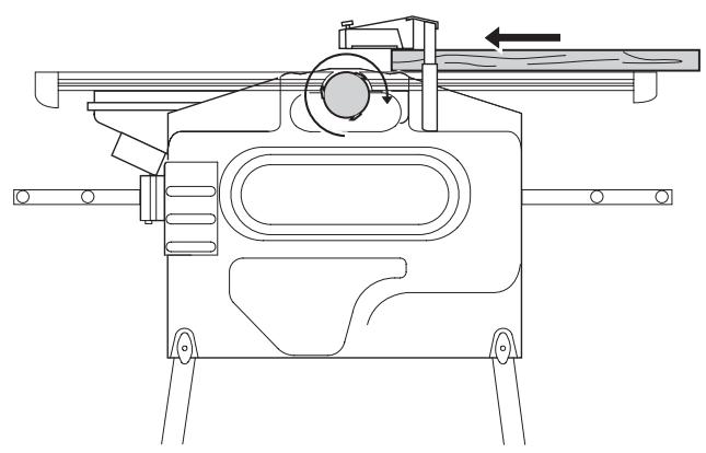
Planing (fig. N1 & N2)
- Mount the shavings collector as described above.
- Adjust the fence as required.
- Adjust the guard to provide optimum screening.
- Set the depth of cut.
- Switch on the machine.
- Slowly feed the workpiece underneath the guard, keeping it firmly pressed against the fence.
- Feed the workpiece in the direction of the grain.
- Remember to use the push stick when close to the cutterhead.
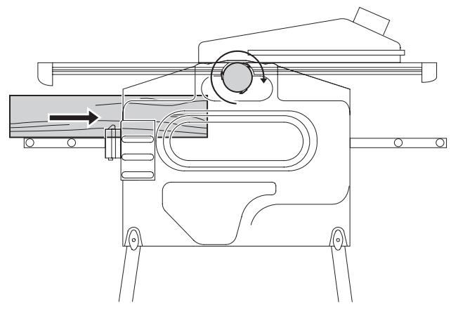
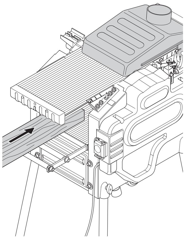
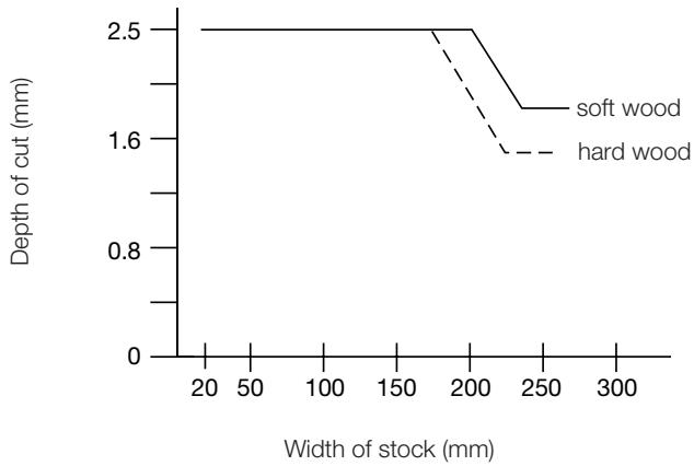
Thicknessing (fig. O1 & O2)
- Mount the shavings collector as described above.
- Set the depth of cut.
- Switch on the machine.

- Best results are achieved when the workpiece has at least one flat surface.
- For optimal results, plane both sides of the workpiece to reach the desired thickness.
Follow the depth of cut and width guidelines shown in the table below.
line
| Width of stock (mm) | soft wood | hard wood | | ------------------- | --------- | --------- | | 20 | 2.5 | 2.5 | | 200 | 2.5 | 2.5 | | 250 | 1.6 | 1.6 |- Slowly feed the workpiece into the machine.
- Feed the workpiece in the direction of the grain.
Snipe
Snipe is a depression made when the ends of the workpiece contact the cutters. To avoid snipe:
- Keep the workpiece level throughout the planing operation.
- Feed the workpiece flat against the table.
Warping (fig. P1 - P4)
If your workpiece is only slightly warped, plane both sides to produce the desired thickness.
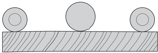
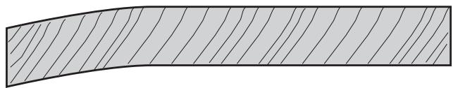
Bowed workpieces (fig. P1 & P2)
The feed rollers and cutterhead will temporarily flatten the workpiece (fig. P1). The bowed shape, however, will return after planing (fig. P2).
- To remove the bow, use a jointer.
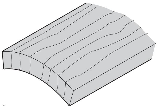
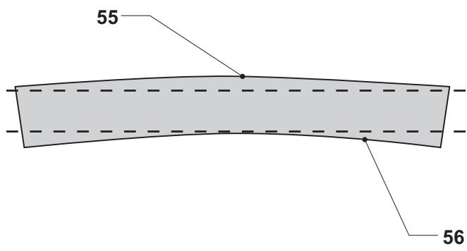
Cupped workpieces (fig. P3 & P4)
- Rip the cupped workpiece in the middle (fig. P3).
- Plane the pieces separately to eliminate waste.
- Alternatively, plane the top flat (55) first, turn the workpiece over and plane the bottom flat (56) (fig. P4).
Dust extraction (fig. A)
The machine is provided with a 100 mm dust extraction port on the shavings collector (4). Provided with a suitable dust extraction device, 90% of the produced shaving can be caught if the air flow is at least 20 m/s.
- Connect a suitable dust extraction device during all operations.
- Whenever possible, connect a dust extraction device designed in accordance with the relevant regulations regarding dust emission.
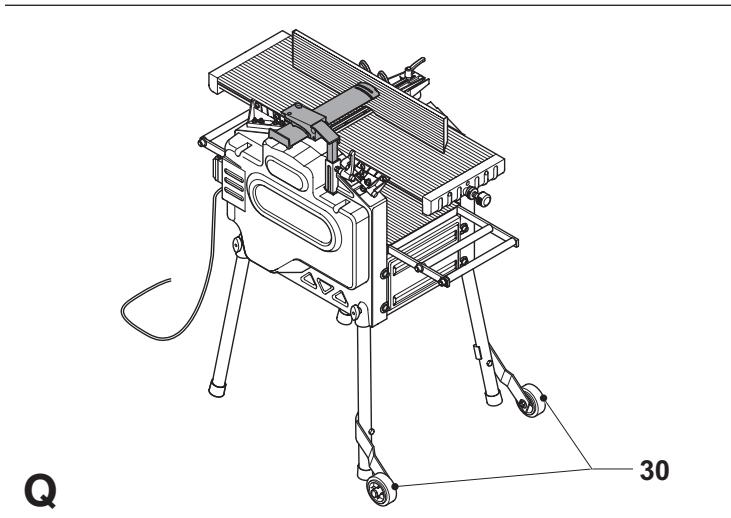
Transporting (fig. Q)
The castor wheels (30) provide an easier transport of the machine.
Optional accessories
Consult your dealer for further information on the appropriate accessories.
These include spare cutting blades (DE7330).
Maintenance
Your DEWALT machine has been designed to operate over a long period of time with a minimum of maintenance. Continuous satisfactory operation depends upon proper tool care and regular cleaning.
Replacing the blades (fig. R1 & R2)
The machine is equipped with a cutterhead that holds two blades.

Always replace the blades simultaneously.

Sharp edges.

Wear gloves when replacing the blades.

Prior to replacing the blades always unplug the machine.
Removing the blades
- Remove the fence and the guard.
- Carefully rotate the cutterhead (57) until the first blade becomes visible.
- Loosen the bolts (58) using the spanner supplied.
- Lift the blade assembly (59) out of the cutterhead. Use a pair of pliers if necessary.
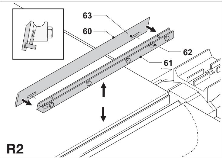
• Take the blade (60) from the holder (61). - Repeat as for the other blade.
Fitting the blades
- Attach the blade (60) to the blade holder (61). Make sure that the outer bolt heads (62) fall in notches (63).
- Re-fit the assembly into the cutterhead (57).
- Adjust the blade as described below.
- Tighten the bolts (58) (torque: 6-8 Nm).
- Repeat as for the other blade.
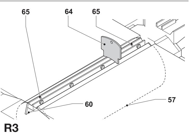
Adjusting the blades (fig. R3)
- Check the position of the blade (60) at both ends.
- Position the gauge (64) over the cutterhead (57) as shown.
- The bottom edge of the gauge must coincide with the tip of the blade (60).
- If adjustment is required, proceed as follows:
- Turn each adjusting screw (65) in or out as necessary until the blade tip coincides with the gauge.
Re-sharpening the blades
The blades can be re-sharpened at 42^ .

The blades can be re-sharpened max. 3 mm down to their original size. If the blade size has decreased by more than 3 mm, the blades have to be replaced.

Lubrication
Your power tool requires no additional lubrication.

Cleaning
Keep the ventilation slots clear and regularly clean the housing with a soft cloth.
- Keep the tables clean and free from grease. Regularly apply some wax to the tables.
- Keep the machine free from dust and shavings.
- On a daily basis, check and clean the kickback and feed spindles.

Unwanted tools and the environment
Take your tool to an authorized DEWALT repair agent where it will be disposed of in an environmentally safe way.
GUARANTEE
• 30 DAY NO RISK SATISFACTION GUARANTEE •
If you are not completely satisfied with the performance of your DeWALT machine, simply return it within 30 days, complete as purchased, to the point of purchase, for a full refund or exchange. Proof of purchase must be produced.
• ONE YEAR FREE SERVICE CONTRACT •
If you need maintenance or service for your DEWALT machine, in the 12 months following purchase, it will be undertaken free of charge at an authorized DEWALT repair agent. Proof of purchase must be produced. Includes labour and spare parts for Power Tools. Excludes accessories.
- ONE YEAR WARRANTY •
If your DEWALT product becomes defective due to faulty materials or workmanship within 12 months from the date of purchase, we guarantee to replace all defective parts free of charge or, at our discretion, replace the unit free of charge provided that:
- The product has not been misused.
• Repairs have not been attempted by unauthorized persons.
• Proof of purchase date is produced.
This guarantee is offered as an extra benefit and is additional to consumers statutory rights.
For the location of your nearest authorized DEWALT repair agent, please use the appropriate telephone number on the back of this manual. Alternatively, a list of authorized DEWALT repair agents and full details on our after-sales service are available on the Internet at www.2helpU.com
CEPILLADORA REGRUESADORA D27300/D27300T
¡Enhorabuena!
Director Engineering and Product Development
Horst Großmann
$$ \chi . f o p s m a n $$
Product and Safety GmbH (TRPS)
Am Grauen Stein 1
D-51105 Köln
Germany
| Cert. No. | |
| 21111827 001 |
Product and Safety GmbH (TRPS)
Am Grauen Stein 1
D-51105 Köln
Germany
| Cert. No. | |
| 21111827 001 |
L'emballage contient:
PIALLATRICE A SPESSORE D27300/D27300T
Congratulazioni!
Product and Safety GmbH (TRPS)
Am Grauen Stein 1
D-51105 Köln
Germany
| Cert. No. |
| 21111827 001 |
VANDIKTE-SCHAAFBANK D27300/D27300T
Gefeliciteerd!
Director Engineering and Product Development
Horst Großmann
$$ \chi . f o p s m a n $$
Product and Safety GmbH (TRPS)
Am Grauen Stein 1
D-51105 Köln
Germany
| Cert. No. | |
| 21111827 001 |
Director Engineering and Product Development
Horst Großmann
$$ \chi . f o p s m a n $$
Product and Safety GmbH (TRPS)
Am Grauen Stein 1
D-51105 Köln
Germany
Director Engineering and Product Development
Horst Großmann
$$ \chi . f o p s m a n $$
Product and Safety GmbH (TRPS)
Am Grauen Stein 1
D-51105 Köln
Germany
| Cert. No. | |
| 21111827 001 |
11 Retire as chaves de ajuste
Voltar a afiar as lâminas
Director Engineering and Product Development
Horst Großmann
$$ \chi . f o p s m a n $$
Product and Safety GmbH (TRPS)
Am Grauen Stein 1
D-51105 Köln
Germany
Cert. No.
21111827 001
Turvaohjeet
Director Engineering and Product Development
Horst Großmann
$$ \chi . f o p s m a n $$
Product and Safety GmbH (TRPS)
Am Grauen Stein 1
D-51105 Köln
Germany
| Cert. No. | |
| 21111827 001 |
Product and Safety GmbH (TRPS)
Am Grauen Stein 1
D-51105 Köln
Almanya
| Vesika numarası | |
| 21111827 001 |
Product and Safety GmbH (TRPS)
Am Grauen Stein 1
D-51105 Köln
Germany
| Cert. No. | |
| 21111827 001 |