FS4000 - Power Tools MAKITA - Free user manual and instructions
Find the device manual for free FS4000 MAKITA in PDF.
| Product type | Electric screwdriver |
| Brand | Makita |
| Model | FS4000 |
| Self-drilling screw capacity | 6 mm |
| Self-tapping screw capacity | 5 mm |
| No-load speed | 0 - 4,000 min⁻¹ |
| Overall length | 269 mm |
| Net weight | 1.3 kg |
| Power supply | Single-phase mains, double insulation (no earth connection required) |
| Safety class | Double insulation (Class II) |
| Direction of rotation | Reversing switch (right/left) |
| Depth adjustment | By locking ring (1 turn = 1.5 mm) |
| Clutch | Slip clutch, pressure engagement |
| Light | LED (integrated, lights up with trigger) |
| Hook | Yes, for temporary suspension |
| Bit holder | Magnetic or quick-release depending on version |
| Centering sleeve | With storage support |
| Continuous operation | With lock button |
| Sound pressure level | 82 dB(A) |
| Sound power level | 93 dB(A) |
| Vibration emission | ≤ 2.5 m/s² (screwdriving without impact) |
Frequently Asked Questions - FS4000 MAKITA
User questions about FS4000 MAKITA
0 question about this device. Answer the ones you know or ask your own.
Ask a new question about this device
Download the instructions for your Power Tools in PDF format for free! Find your manual FS4000 - MAKITA and take your electronic device back in hand. On this page are published all the documents necessary for the use of your device. FS4000 by MAKITA.
USER MANUAL FS4000 MAKITA
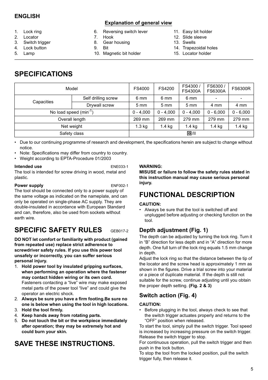
Explanation of general view
-
Lock ring
-
Reversing switch lever
-
Easy bit holder
-
Locator
-
Hook
-
Slide sleeve
-
Switch trigger
-
Gear housing
-
Swells
-
Lock button
-
Bit
-
Trapezoidal holes
-
Lamp
-
Magnetic bit holder
-
Locator holder
SPECIFICATIONS
| Model | FS4000 | FS4200 | FS4300 / FS4300A | FS6300 / FS6300A | FS6300R | |
| Capacities | Self drilling screw | 6 mm | 6 mm | 6 mm | - | - |
| Drywall screw | 5 mm | 5 mm | 5 mm | 4 mm | 4 mm | |
| No load speed (min-1) | 0 - 4,000 | 0 - 4,000 | 0 - 4,000 | 0 - 6,000 | 0 - 6,000 | |
| Overall length | 269 mm | 269 mm | 279 mm | 279 mm | 279 mm | |
| Net weight | 1.3 kg | 1.4 kg | 1.4 kg | 1.4 kg | 1.4 kg | |
| Safety class | 回/II | |||||
- Due to our continuing programme of research and development, the specifications herein are subject to change without notice.
Note: Specifications may differ from country to country.
Weight according to EPTA-Procedure 01/2003
Intended use
ENE033-1
The tool is intended for screw driving in wood, metal and plastic.
Power supply
ENF002-1
The tool should be connected only to a power supply of the same voltage as indicated on the nameplate, and can only be operated on single-phase AC supply. They are double-insulated in accordance with European Standard and can, therefore, also be used from sockets without earth wire.
SPECIFIC SAFETY RULES
GEB017-2
DO NOT let comfort or familiarity with product (gained from repeated use) replace strict adherence to screwdriver safety rules. If you use this power tool unsafely or incorrectly, you can suffer serious personal injury.
- Hold power tool by insulated gripping surfaces, when performing an operation where the fastener may contact hidden wiring or its own cord.
Fasteners contacting a "live" wire may make exposed metal parts of the power tool "live" and could give the operator an electric shock. - Always be sure you have a firm footing.Be sure no one is below when using the tool in high locations.
- Hold the tool firmly.
- Keep hands away from rotating parts.
- Do not touch the bit or the workpiece immediately after operation; they may be extremely hot and could burn your skin.
SAVE THESE INSTRUCTIONS.
WARNING:
MISUSE or failure to follow the safety rules stated in this instruction manual may cause serious personal injury.
FUNCTIONAL DESCRIPTION
CAUTION:
- Always be sure that the tool is switched off and unplugged before adjusting or checking function on the tool.
Depth adjustment (Fig. 1)
The depth can be adjusted by turning the lock ring. Turn it in "B" direction for less depth and in "A" direction for more depth. One full turn of the lock ring equals 1.5mm change in depth.
Adjust the lock ring so that the distance between the tip of the locator and the screw head is approximately 1mm as shown in the figures. Drive a trial screw into your material or a piece of duplicate material. If the depth is still not suitable for the screw, continue adjusting until you obtain the proper depth setting. (Fig. 2 & 3)
Switch action (Fig. 4)
CAUTION:
- Before plugging in the tool, always check to see that the switch trigger actuates properly and returns to the "OFF" position when released.
To start the tool, simply pull the switch trigger. Tool speed is increased by increasing pressure on the switch trigger. Release the switch trigger to stop.
For continuous operation, pull the switch trigger and then push in the lock button.
To stop the tool from the locked position, pull the switch trigger fully, then release it.
NOTE:
- Even with the switch on and motor running, the bit will not rotate until you fit the point of the bit in the screw head and apply forward pressure to engage the clutch.
Lighting up the lamps
For Models
FS4200, FS4300, FS4300A, FS6300, FS6300A, FS6300R (Fig. 5)
CAUTION:
- Do not look in the light or see the source of light directly.
To turn on the lamp, pull the trigger. Release the trigger to turn it off.
NOTE:
- Use a dry cloth to wipe the dirt off the lens of lamp. Be careful not to scratch the lens of lamp, or it may lower the illumination.
Reversing switch action (Fig. 6)
CAUTION:
Always check the direction of rotation before operation.
- Use the reversing switch only after the tool comes to a complete stop. Changing the direction of rotation before the tool stops may damage the tool.
This tool has a reversing switch to change the direction of rotation. Move the reversing switch lever to the position (A side) for clockwise rotation or the position (B side) for counterclockwise rotation.
Hook (Fig. 7)
The hook is convenient for temporarily hanging the tool.
ASSEMBLY
CAUTION:
Always be sure that the tool is switched off and unplugged before carrying out any work on the tool.
Installing or removing the bit
To remove the bit, first remove the locator by pulling the lock ring away from the gear housing. (Fig. 8)
Then check the type of bit holder that your tool employs. If it has silver colored solid sleeve, it is "magnetic connect bit holder". If it has gold and silver colored separate sleeves, it is "easy-connect bit holder".
For tool with magnetic bit holder
Grasp the bit with a pair of pliers and pull the bit out of the magnetic bit holder. Sometimes, it helps to wiggle the bit with the pliers as you pull.
To install the bit, push it firmly into the magnetic bit holder. Then install the locator by pushing it firmly back onto the gear housing. (Fig. 9)
For tool with easy-connect bit holder
Keep fully pushing the slide sleeve, which is a gold colored part of the easy bit holder, toward the tool and pull the bit out of the easy bit holder. (Fig. 10 & 11)
To install the bit, push it firmly into the easy bit holder. Then install the locator by pushing it firmly back onto the gear housing. (Fig. 12)
Installing removable cord adapter
For Model FS6300R (Fig. 13)
Insert the removable cord adapter as far as it goes so that the marking on an end of the removable cord adapter on the side of connecting to power supply cord is aligned to the marking 回 on the other end of the removable cord adapter on the side of connecting to the tool.
Turn the removable cord adapter clockwise until it is locked with a lock button. (Fig. 14)
And at this time the marking on an end of the removable cord adapter on the side of power supply cord is aligned to the marking 岛 on the other end of the removable cord adapter on the side of connecting to the tool. (Fig. 15)
Removing removable cord adapter (Fig. 16)
Rotate the removable cord adapter counterclockwise until it stops while pressing the lower part of the lock button.
Then pull the removable cord adapter in that position. (Fig. 17)
Use of locator holder (Fig. 18)
The locator can be temporarily held on the locator holder during replacing bit or using without locator. To hold the locator, position the trapezoidal holes of the locator on the swells of the locator holder and push it in.
OPERATION (Fig. 19)
Fit the screw on the point of the bit and place the point of the screw on the surface of the workpiece to be fastened. Apply pressure to the tool and start it. Withdraw the tool as soon as the clutch cuts in. Then release the switch trigger.
CAUTION:
- When fitting the screw onto the point of the bit, be careful not to push in on the screw. If the screw is pushed in, the clutch will engage and the screw will rotate suddenly. This could damage a workpiece or cause an injury.
- Make sure that the bit is inserted straight in the screw head, or the screw and/or bit may be damaged.
- Hold the tool only by the handle when performing an operation. Do not touch the metal part.
MAINTENANCE
CAUTION:
Always be sure that the tool is switched off and unplugged before attempting to perform inspection or maintenance.
To maintain product SAFETY and RELIABILITY, repairs, carbon brush inspection and replacement, any other maintenance or adjustment should be performed by Makita Authorized Service Centers, always using Makita replacement parts.
ACCESSORIES
CAUTION:
- These accessories or attachments are recommended for use with your Makita tool specified in this manual.
The use of any other accessories or attachments might present a risk of injury to persons. Only use accessory or attachment for its stated purpose.
If you need any assistance for more details regarding these accessories, ask your local Makita Service Center.
- Phillips Insert bits
- Magnetic bit holder
- Locator
- Plastic carrying case
Easy bit holder
For European countries only
ENG102-1
Noise
The typical A-weighted noise level determined according to EN60745:
Sound pressure level (L_PA) .. 82 dB A
Sound power level (L_WA) : 93 dB (A)
Uncertainty (K): 3 dB (A)
Wear ear protection
Vibration
ENG204-2
The vibration total value (tri-axial vector sum) determined according to EN60745:
Work mode: screwdriving without impact
Vibration emission (a_h) : 2.5m / s^2 or less
Uncertainty (K): 1.5m / s^2
EC Declaration of Conformity
ENH101-10
We Makita Corporation as the responsible manufacturer declare that the following Makita machine(s):
Designation of Machine: Drywall Screwdriver
Model No./ Type: FS4000, FS4200, FS4300, FS6300, FS6300R
are of series production and
Conforms to the following European Directives:
98/37/EC until December 28th 2009 and then with
2006/42/EC from 29th December 2009
And are manufactured in accordance with the following
standards or standardised documents:
EN50144, EN60745
The technical documentation is kept by our authorised representative in Europe who is:
Makita International Europe Ltd,
Michigan, Drive, Tongwell,
Milton Keynes, MK15 8JD, England
10 th September 2008

Tomoyasu Kato
Director
Makita Corporation
3-11-8, Sumiyoshi-cho,
Anjo, Aichi, JAPAN
Descriptif
Michigan, Drive, Tongwell,
Milton Keynes, MK15 8JD, Angleterre
3-11-8, Sumiyoshi-cho,
Anjo, Aichi, JAPON
Michigan, Drive, Tongwell,
Milton Keynes, MK15 8JD, England
- September 2008

Tomoyasu Kato
Direktor
Makita Corporation
3-11-8, Sumiyoshi-cho,
Anjo, Aichi, JAPAN
ITALIANO
Michigan, Drive, Tongwell,
Milton Keynes, MK15 8JD, Inghilterra
10 settembre 2008

Tomoyasu Kato
Direttore
Makita Corporation
3-11-8, Sumiyoshi-cho,
Anjo, Aichi, JAPAN
Michigan Drive, Tongwell,
Milton Keynes, MK15 8JD, England
10 September 2008

Tomoyasu Kato
Director
Makita Corporation
3-11-8, Sumiyoshi-cho,
Anjo, Aichi, JAPAN
Michigan, Drive, Tongwell
Milton Keynes, MK15 8JD, Inglaterra
3-11-8, Sumiyoshi-cho,
Anjo, Aichi, JAPAN
Descrição geral
Michigan, Drive, Tongwell
Milton Keynes, MK15 8JD, Inglaterra
3-11-8, Sumiyoshi-cho,
Anjo, Aichi, JAPAN
FS4200, FS4300, FS4300A, FS6300, FS6300A,
FS6300R (Fig. 5)
FORSIGTIG:
- Se/DD direkte ind i lyset ell lyskilden.
Michigan, Drive, Tongwell,
Milton Keynes, MK15 8JD, England
- september 2008

Tomoyasu Kato
Direktor
Makita Corporation
3-11-8, Sumiyoshi-cho,
Anjo, Aichi, JAPAN
Evikn Pepiyapn
PuBIOATE TO KLEIDWU ETOI WOTE N ATIOOTAAN METAU TNC AOKN TS O UVOTIOIATN KAI TNC KEPAIAI NTS BIDAC VA EIVAI TEPIITOU 1 MMOTC DEIXVETA I STA OXEDIAYPUMATA.
Biodote pia bokiaoataki Bida e o a 0uliko oac n o
Eva TnvooioTTO uIko.Eav akoun To baoos 6ev Eivai kataaAho yia Tn Bia, ouvexiote Tn puoiion EwC otou va atoktnaete nTv kataalnn npuoiian yia to baoos. (Eik.2 ka3)
i k (Eik. 4)
PPOEOXH:
Piv ouvEeTo epyaleio, TAVTOVE VA EeYExe Oti n 0kavdaan- diakottnc Evpeytoieitai KAVOVIKA KAI ETIOPTpeei OTn eoN OFFF'OTAVTN apVte.
Ia va EKivnoTe To epyaleio, aTla TnatoTe Tn
OakovdAan-diaKoTTn. AvuGNoTe Tnv TIEOn otN
OakovdAan-diaKoTTn, auGavetai n taXutnta Tou epyaleiou.
Ia va otatnatnoTe To epyaleio, apnoTe Tnv OkaVdAanDiaKoTTn.
Tia ouvexoevn aeitoupyia, tnatote tn okaovdaan- diakottnkai katoiv tnatote to koumiti aoapalianc. Tia va byalete to epyaieio atto nTv kkeiowevn teon, tioge evtawoc tnokavdaan-diaikottnkai katotntiv aqnoTe tnv.
ZHMEIΩΣH:
AkoJn kai av aokavdaJn evai evepyn kai to potep oE aeIoouyia, nutn dev 0a Tepiotpapei EwC otou ToTOnOeTneTe nutn mavw otny KepaI Nc BiOa cai aKaKoTe Tneon TPOC TAETPOCs YIA VA EMTAAkei O ouPTAEKtnc.
AvmaTovlambda
Tia ta oovrEa
FS4200, FS4300, FS4300A, FS6300, FS6300A,
FS6300R (EIK.5)
PPOEOXH:
Mny koitate kateuthetaiav meo a oTo n otyn tynn tou
Tia va avayet n laut, tpaBnEe Tn oKavdaan. Ia va Tn afoe, afoe Tn oKavdaan.
ZHMEIΩΣH:
XpəiOIOInATE eva OTEyVIOAVia oKoUIOeT Nv Okovn anto foako Tns AouTAC. PoooeTe va un ypaotouviTe to kaO nL aouTAC, ETEIDn mTOpei va ueiwei n Evtaan Tou quoiouou.
p o i k o (Eik. 6)
PPOEOXH:
- Pniv atio tn aeitoupyia, va eAeVxTe TAVTO Tnv KATEUUVAN TEPiOtpoPfC.
Na xpaaiottoieTe oavaatpokio movTo epyaalei evi evalwacikntoTIOeAv aaaleTe Tnv kateubuvan TepiopKnTPOivkavntOTOINeI To epyaalei, mTOpoe i vtpoknEβaBn OTO epyaalei.
To epyaieio auto diatheiaavaotpokio ia va aaiazTe TnV KATEUuvon TEPIOTPOPHC. MetakivnoTe to avaotpokio stn then (TLEUPA A) yia 0e1oTOPON TEPIOPTPOH n tOn then (TLEUPA B) yia apiotepoTOPON TEPIOTOPOH.
Γαντζος (Eik. 7)
O yavToc xpoiuevi to ppoomega kpmaa taou epyaliou.
ΣYNAPMOΛΟΓΗΞH
PPOEOXH:
Na 8aiveoTAVOTTO EyaEio evai oBnTo kai aTOOUVDeEeVO TO nAekptiKO pUma TIV EKTEAEETOIOAONTOEpyoia Oe auto.
ToTOnTnOn n aPaipeoN tnsmuTns
Tia va aapaiaeata nJ mutn, Tpwa aapaieote tov EVtntiTn tpaBwtac naqpi Toa aapaiotko daKTluo AtTo To KApUoc TwO oDovTTOxWv. (Eik.8)
Tn ouvexia eelyte tov tTO Tou OTnpiymuoc Tns mUTNS Tou diaTei to evyaleio aC.
Eav diahevi eva oTepeo bpaixova aonuviou xpawatoc, tote autoreivai eva eva 巧 Tnpiymu uTnc me ayvntikn ouvean. Eav diahevi exwipatouc bpaxioe xpuoo kai anenoviu xpawatoc, tote autoreivai eva 巧 Tnpiymu uTnc me eukoan ouvean.
Tia to epyaieioe to yayntiko otnpiyu autns
Tiaote nutmteia tavaia kai tpaBxi Te nV Eg wto yayntko ot npiyua nts mtns. MepiKc opeC 0a Bontheta ev atipoyupice Tn utn e Tnv tavaia kaohs nTv patae.
Tia va totoBetnEte Tn mtn, ottpwEeTe Tnv yepa meo OTO maayvntko OTnpiyua ts nucns. Meta totoBETnATE TOV EVtOITnT oTIPWxovTAC To vepa poc ta Tiaw TWAO KELUPOC TOW ODOTOTPOXUV.(Eik.9)
Tia to epyaaleio me to otnpiyma utns nts eukoans ouvdoens
Michigan, Drive, Tongwell,
Milton Keynes, MK15 8JD, England
3-11-8, Sumiyoshi-cho,
Anjo, Aichi, JAPAN
Makita Corporation
Anjo, Aichi, Japan
884894-996