
ST 602819 - Motion detector STEINEL - Free user manual and instructions
Find the device manual for free ST 602819 STEINEL in PDF.


| Product type | Infrared motion detector |
| Brand | Steinel |
| Model | ST 602819 (IS 240 DUO) |
| Dimensions (H x W x D) | 90 x 60 x 100 mm |
| Weight | Approx. 300 g |
| Power supply | 230 – 240 V, 50 Hz |
| Maximum power (incandescent/halogen lamps) | 1000 W |
| Maximum power (LED) | 16 W (LED < 2 W) / 64 W (LED > 2 W) |
| Detection angle | 240° with 180° angular opening |
| Maximum range | 12 m (electronically stabilized) |
| Adjustable timer | 10 s to 15 min |
| Twilight setting | 2 – 2000 lux |
| Protection rating | IP 54 |
| Recommended mounting height | Approx. 2 m |
| Detector orientation | ± 80° |
| Number of pyroelectric detectors | 2 |
| Electrical connections | Terminals L, N, L', PE (ground) |
| Masking covers included | Yes (for lens segments) |
| Manufacturer warranty | 3 years (36 months) |
| Operating temperature | Not specified (estimated -20°C to +50°C) |
| Maintenance and cleaning | Clean the lens with a damp cloth, no detergent |
| Safety | Cut off power before any intervention, comply with standard NF C-15100 |
| Spare parts and repairability | Contact the nearest Steinel after-sales service |
| Intended use | Automatic switching of lighting and alarm (not anti-intrusion) |
Frequently Asked Questions - ST 602819 STEINEL
User questions about ST 602819 STEINEL
0 question about this device. Answer the ones you know or ask your own.
Ask a new question about this device
Download the instructions for your Motion detector in PDF format for free! Find your manual ST 602819 - STEINEL and take your electronic device back in hand. On this page are published all the documents necessary for the use of your device. ST 602819 by STEINEL.
USER MANUAL ST 602819 STEINEL
Contact
www.steinel.de/contact


Intelligent technology

Information
IS240DUO


2




3

GB - Installation instructions

Safety instructions
■ Disconnect the power supply before attempting any work on the motion detector.
During installation, the electric power cable to be connected must be voltage-free. Therefore, switch off the power first and check freedom from voltage with a voltage detector.
■ Installing the motion detector involves work on the mains power supply. This work must therefore be carried out professionally in accordance with the applicable national wiring regulations and electrical operating conditions (e.g. DE-VDE 0100, AT-ÖVE-EN 1, CH-SEV 1000).
Principle
Lights, alarms, and many other things triggered by movement - for your convenience and safety.
Whether a house door, garage, patio or carport, stairs, a storeroom or cellar are involved, this infrared motion detector is rapidly installed and ready for operation anywhere.
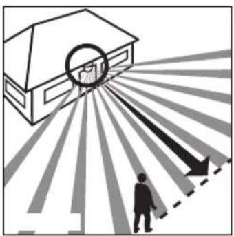
The IS 240 DUO is equipped with two 120° pyro sensors which detect the invisible heat emitted by moving objects (pedestrians, animals etc.).
The heat thus detected is electronically converted and switches ON connected consumers (e.g. a light). No heat radiation is detected through obstacles, such as walls or glass and no switching therefore occurs. The two pyro sensors have a detection angle of 240° with an opening angle of 180° .
Important: the safest motion detection is obtained when the device is mounted and aligned laterally to the walking direction and no obstacles (such as trees and walls, for example) obstruct the view.
Installation
■ Wall mounting
Warning: installation involves a mains connection. With 230 V, a risk of electrocution exists! Therefore, switch off the power first and check freedom from voltage with a voltage tester. Installation of the sensor involves work on the mains power supply; this work must therefore be carried out professionally in accordance with regulations. Please note that the motion detector must be protected by a 10 A circuit breaker.
The installation site should be at least 50 cm from a light, since the latter's heat radiation could result in false triggering of the sensor. The installation height should be approx. 2 m.
Unscrew the fastening screw ■ counterclockwise with a screw-driver, slide down the mounting plate ■ and remove it. Do not undo the internal wiring to the terminal block, but extract the block by pulling it gently.
Insert the rubber plugs into the mounting plate. Hold the mounting plate against the wall and mark the drill holes (paying attention to the wiring arrangement in the wall), drill the holes and insert the dowels. In order to be able to perform a switching operation, a power supply lead with at least two phases must run to the unit and a second lead out to the consumer. The two rubber plugs can be pierced for this purpose with a screwdriver. Two lugs are provided on the bottom of the wall fastener for surface wiring. These can be snapped off easily. After passing the wiring through, the mounting plate can be screwed in place.
■ Connection of the mains lead
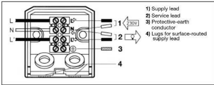
The mains lead consists of a 2-3 phase cable.
L =phase conductor (usually black, brown or grey)
N =neutral conductor (usually blue)
PE = protective-earth conductor, if present (green/yellow)
If in doubt, the cable must be identified with a voltage tester. Switch off the current again. The wire terminals are for the mains lead. The phase conductor (L) is connected from above to the first terminal (see arrow) and the neutral conductor (N) to the second terminal. If the green/yellow protective-earth conductor is present, connect this to the bottom terminal provided.
■ Connection of the service lead
The service lead (e.g. light) likewise consists of a 2-3 phase cable which is connected to terminals N and L'. The phase conductor of the consumer (black, brown or grey cable) is connected to the terminal marked
L'. The neutral conductor (blue cable) is clamped to the terminal marked N together with the mains lead neutral conductor. Connect any green/yellow protective-earth conductor to the lower terminal.
Important: Getting the cable connections crossed will produce a short circuit in the unit or in your fuse box. In this case, the individual wires must be re-identified and re-connected. A mains switch for ON and OFF switching can of course be installed in the mains lead.
Wiring examples

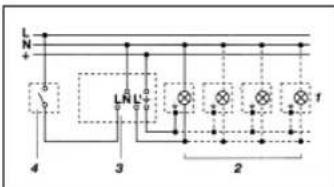
- Fixture without neutral conductor 2. Fixture with neutral conductor


-
Connection via series switch for manual and automatic operation
-
Connection to double-throw switch for permanent light and automatic operation
Setting I: automatic operation
Setting II: manual operation for permanent light Important:
The unit cannot be switched off, only optional operation between settings I and II.
1) e.g. 1–4 x 100 W filament bulbs
2) consumer, lighting max. 1000 W (refer to Technical specifications)
3) IS 240 DUO connection terminals
4) indoor switch
5) indoor series switch, manual, automatic
6) indoor double-throw switch, automatic, permanent light
Function
After the motion detector has been connected and fastened to its wall mount, two setting options are available after removing the decorative ring 21. the system can be switched ON.

Switch-off delay (time setting)
(Factory setting: 10 sec.)
Light ON duration can infinitely varied from approx. 10 sec. to a maximum of 15 min. Control dial set to (1) = shortest time (10 sec.) Control dial set to (6) = longest time (15 min.) The shortest time setting is recommended when adjusting the detection zone and performing the function test.
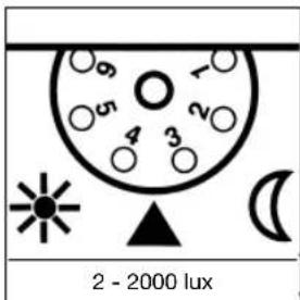
Twilight setting
(Factory setting: 2000 lux)
The sensor's response threshold can be infinitely varied from 2 – 2000 lux. Control dial set to (1) = daylight operation at approx. 2000 lux. Control dial set to (6) = night-time operation at approx. 2 lux. The adjusting screw must be turned fully anti-clockwise when adjusting the detection zone and performing the function test in daylight.
Reach setting/adjustment
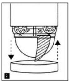
Assuming an installation height of 2 m, the maximum reach of the sensor is 12 m. Optimum adjustment of the detection zone is possible according to needs. The shrouds ▶ provided serve to cover any desired number of lens segments and individually reduce the reach. Fine adjustment is also possible by turning the sensor housing ▶ by ± 80°. The shrouds ▶ can be divided vertically or horizontally along
the grooved divisions, or cut with scissors. After removing the decorative ring 2, the shrouds are to be suspended on the upper part of the sensor lens. The decorative ring 3 is subsequently to be reapplied and the shrouds 4 are fixed firmly in place. False switching by cars and pedestrians, etc. is therefore ruled out, or risk areas deliberately monitored.
Technical specifications
| Dimensions (H x W x D): 90 x 60 x 100 mm | |
| Output: | Incandescent / halogen lamp load 1000 W |
| Fluorescent-lamp electronic ballasts 1000 W | |
| Fluorescent lamps, uncorrected 500 VA | |
| Fluorescent lamps, series-corrected 500 VA | |
| Fluorescent lamps, parallel-corrected 500 VA | |
| Low-voltage halogen lamps 1000 VA | |
| LED < 2 W 16 W | |
| 2 W < LED < 8 W 64 W | |
| LED > 8 W 64 W | |
| Capacitive load 132 μF | |
| Connection: 230-240 V, 50 Hz | |
| Angle of coverage: 240° (with 180° angle of aperture) | |
| Pivoting range of the sensor: Fine adjustment ± 80° | |
| Reach: max. 12 m (electronically stabilised) | |
| Time setting: 10 sec. - 15 min. | |
| Twilight setting: 2 - 2000 lux | |
| IP rating: IP 54 | |
Troubleshooting
| Malfunction Cause | Remedy | |
| IS 240 DUO without power | ■ Fuse has blown; not switched ON | ■ Replace fuse, switch ON mains switch, check wiring with voltage tester |
| ■ Short-circuit | ■ Check connections | |
| IS 240 DUO does not switch ON | ■ Twilight setting in night-time mode during daytime operation | ■ Adjust setting |
| ■ Bulb burned out | ■ Replace light bulb | |
| ■ Power switch OFF | ■ Switch ON | |
| ■ Fuse blown | ■ Replace fuse, check connection if necessary | |
| ■ Detection zone not correctly adjusted | ■ Readjust | |
| IS 240 DUO does not switch OFF | ■ Continued movement within the detection zone | ■ Check zone and readjust if necessary or apply shroud |
| ■ Switched ON light is within detection zone and switches ON again as a result of temperature change | ■ Readjust zone or apply shroud | |
| ■ Set to continuous operation by indoor series switch | ■ Series switch to automatic | |
| ■ Position Wi-Fi device very close to the sensor | ■ Increase distance between Wi-Fi device and sensor | |
| IS 240 DUO keeps switching ON/OFF | ■ Switched ON light is within detection zone | ■ Adjust detection zone or apply shrouds, increase distance |
| ■ Animals moving in detection zone | ■ Adjust zone or apply shrouds | |
Malfunction Cause Remedy
| IS 240 DUO switchesON when it should not | ■ Wind is moving trees and bushes in the detection zone■ Cars in the street are detected■ Sudden temperature changes due to weather (wind, rain, snow) or exhaust air from fans or open windows■ Position Wi-Fi device very close to the sensor | ■ Adjust zone or apply shrouds■ Adjust zone or apply shrouds■ Adjust detection zone or install in a different place■ Increase distance between Wi-Fi device and sensor |
Maintenance/care
| The motion sensor is suitable for automatic switching of lights or alarms. The unit is not suitable for special burglary alarm systems, since it lacks the sabotage protection prescribed for this purpose. Weather can affect operation of the sensor. | Strong gusts of wind, snow, rain and hail can cause switching errors, since the sudden temperature changes cannot be distinguished from heat sources. The detection lens ■can be cleaned with a damp cloth (without detergents) if dirty. |
Disposal
Electrical and electronic equipment, accessories and packaging must be recycled in an environmentally compatible manner.

Do not dispose of electrical and electronic equipment as domestic waste.
EU countries only:
Under the current European Directive on Waste Electrical and Electronic Equipment and its implementation in national law, electrical and electronic equipment no longer suitable for use must be collected separately and recycled in an environmentally compatible manner.
Manufacturer's warranty
This STEINEL product has been manufactured with great care, and its operation and safety have been tested in conformity with the current regulations. Production is also submitted to final random-sample testing. STEINEL undertakes the guarantee for perfect condition and function. The warranty period is 36 months, starting on the date of sale to the user. We undertake to remedy faults caused by material or manufacturing defects. This warranty undertaking shall be performed by the repair or replacement of the defective parts, at our own discretion. This warranty shall not cover damage to wearing parts or damage and faults caused by incorrect operation or maintenance. Breakage due to a fall is also not covered. Further consequential damage to external items is excluded.
Claims under warranty shall only be accepted if the product is sent fully assembled and well packed complete with sales slip or invoice (date of purchase and dealer's stamp) to the appropriate Service Centre.
Repair Service:
Please ask your nearest service centre how to proceed for repairing faults not covered by the warranty or occurring after the warranty expires.

FR - Instructions de montage


aprox. 10 seg. - max. 15 min.
2 - 2000 lux
- Tilslutning til manuel eller automatisk drift via serieafbryder
- Tilslutning til konstant belysning eller automatisk drift via skiftekontakt
Position 1:
Automatisk drift
Position II:
Manuel drift, konstant belysning
OBS:
GWARANCJI PRODUCENTA
RO - Instructiuni de montare

3 ANI GARANTIA PRODUCATORULUI

Maždaug 10 s – maks. 15 mi
Išjungimo vėlinimas
2-2000 liuksų


- GB - INSTALLATION INSTRUCTIONS
- SAFETY INSTRUCTIONS
- PRINCIPLE
- WALL MOUNTING
- CONNECTION OF THE MAINS LEAD
- CONNECTION OF THE SERVICE LEAD
- FUNCTION
- SWITCH-OFF DELAY (TIME SETTING)
- TWILIGHT SETTING
- REACH SETTING/ADJUSTMENT
- DISPOSAL
- EU COUNTRIES ONLY
- MANUFACTURER'S WARRANTY
- REPAIR SERVICE
- FR - INSTRUCTIONS DE MONTAGE
- OBS
- RO - INSTRUCTIUNI DE MONTARE
- IŠJUNGIMO VĖLINIMAS
Brand : STEINEL
Model : ST 602819
Category : Motion detector