
GHG 660 LCD - Heat gun BOSCH - Free user manual and instructions
Find the device manual for free GHG 660 LCD BOSCH in PDF.


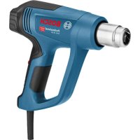
| Product type | Heat gun with LCD display |
| Brand | Bosch |
| Model | GHG 660 LCD |
| Temperature range | 50 °C to 660 °C |
| Air flow | 300 L/min (adjustable) |
| Power | 2200 W |
| Power supply | 230 V, 50 Hz |
| Dimensions (L×W×H) | 250 × 80 × 200 mm |
| Weight | 0.9 kg |
| Display | Digital LCD with precise adjustment |
| Temperature control | Electronic, in 10 °C increments |
| Main functions | Stripping, soldering, shrinking, drying, defrosting |
| Included accessories | Concentrator nozzle, wide nozzle, reflector nozzle, soldering nozzle |
| Thermal protection | Automatic shut-off in case of overheating |
| Protection rating | IP20 |
| Maintenance and cleaning | Clean the ventilation grille with a soft brush, do not use solvents |
| Safety | Integrated rest foot, anti-overheating protection, high-temperature silicone cable |
| Spare parts and repairability | Available via Bosch after-sales service (heating element, switch, nozzles) |
| General information | Supplied with storage case, instruction manual, warranty card |
Frequently Asked Questions - GHG 660 LCD BOSCH
User questions about GHG 660 LCD BOSCH
0 question about this device. Answer the ones you know or ask your own.
Ask a new question about this device
Download the instructions for your Heat gun in PDF format for free! Find your manual GHG 660 LCD - BOSCH and take your electronic device back in hand. On this page are published all the documents necessary for the use of your device. GHG 660 LCD by BOSCH.
USER MANUAL GHG 660 LCD BOSCH
OHJ BUCHI-485-005. book Page 1, Monday, May 14, 2012 9:27 AM
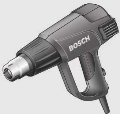
natural_image
Illustration of a Bosch 3D printer with black body and metallic handle (no text or symbols on device)Robert Bosch GmbH
Power Tools Division
70745 Leinfelden Echterdingen
Germany
www.bosch-pt.com
1 609 929 W90 (2012.05) T/143 UNI

GHG 660 LCD Professional

BOSCH


1 609 929 W90 | (14.5.12) Bosch Power Tools
5


∅ 9 mm 1 609 201 797
∅ 14 mm 1 609 201 647
∅ 20 mm 1 609 201 648
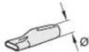
∅ 1,6-4,8 mm 1 609 201 812
∅ 4,8-9,5 mm 1609 201 813
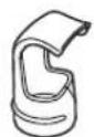
32 mm 1 609 390 453

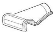
80 mm 1 609 201 751

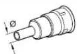
∅9mm 1609201797
∅ 14 mm 1 609 201 647
∅ 20 mm 1 609 201 648

80 mm 1 609 201 751

32 mm 1 609 390 453
6

flowchart
graph TD
    A["1 → 2 → 3 → 4"] --> B["170°C"]
    B --> C["P"]
    C --> D["1 250°C"]
    D --> E["P"]
    E --> F["2 350°C"]
    F --> G["P"]
    G --> H["3 450°C"]
    H --> I["P"]
    I --> J["4 550°C"]

    K["1 250°C"] --> L["P"]
    L --> M["1 320°C"]
    M --> N["P"]
    N --> O["1 320°C"]
    O --> P["5 s"]
    P --> Q["1 320°C"]
Deutsch | 7
Deutsch
Sicherheitshinweise

Read all safety warnings and all instructions. Failure to follow the warnings and instructions may result in electric shock, fire and/or serious injury.
▶ Supervise children. This will ensure that children do not play with the hot air gun.
Children or persons that owing to their physical, sensory or mental limitations or to their lack of experience or knowledge, are not capable of securely operating the hot air gun, may only use this hot air gun under supervision or after having been instructed by a responsible person. Otherwise, there is danger of operating errors and injuries.
▶ Be careful when working with the power tool. The power tool produces intense heat which can lead to increased danger of fire and explosion.
Exercise special care when working close to inflammable materials. The hot air jet or the hot nozzle can ignite dust or gases.
▶ Do not operate or work with the power tool in areas where there is danger of explosion.
▶ Never direct the hot air jet at the same position for longer periods. Easily inflammable gases can develop e.g., when working plastic, paint, varnish or similar materials.





12 | English
▶ Be aware that heat can be conducted to hidden covered materials and can ignite them.
▶ After using, place the power tool down in a secure manner and allow it to cool down completely before packing it away. The hot nozzle can cause damage.
▶ Do not leave the switched-on power tool unattended.
▶ Store idle power tools out of the reach of children. Do not allow persons unfamiliar with the power tool or these instructions to operate the power tool. Power tools are dangerous in the hands of untrained users.
▶ Do not expose the power tool to rain or wet conditions. Water entering a power tool will increase the risk of electric shock.
▶ Do not abuse the cord. Never use the cord for carrying, pulling or unplugging the power tool. Keep cord away from heat, oil, sharp edges or moving parts. Damaged or entangled cords increase the risk of electric shock.
▶ Always wear safety goggles. Safety goggles will reduce the risk of injuries.
▶ Disconnect the plug from the socket outlet before making any adjustments, changing accessories, or placing the power tool aside. This safety measure prevents unintentional starting of the power tool.
▶ Check the power tool, cord and plug each time before use. Do not use the power tool if damage is determined. Do not open the power tool yourself and have it serviced only by a qualified repair person using only original spare parts. Damaged power tools, cords and plugs increase the risk of electric shock.

Provide for good ventilation of your working place. Gas and vapour developing during working are often harmful to one's health.
▶ Wear safety gloves and do not touch the hot nozzle. Danger of burning.
▶ Never direct the hot air jet against persons or animals.
▶ Do not use the power tool as a hairdryer. The hot air being blown out is significantly hotter than that from a hair-dryer.
When operating the power tool in damp environments is unavoidable, use a residual current device (RCD). The use of a residual current device (RCD) reduces the risk of an electric shock.
▶ Never use the machine with a damaged cable. Do not touch the damaged cable and pull the mains plug when the cable is damaged while working. Damaged cables increase the risk of an electric shock.
▶ Products sold in GB only: Your product is fitted with a BS 1363/A approved electric plug with internal fuse (ASTA approved to BS 1362).
If the plug is not suitable for your socket outlets, it should be cut off and an appropriate plug fitted in its place by an authorised customer service agent. The replacement plug should have the same fuse rating as the original plug.
The severed plug must be disposed of to avoid a possible shock hazard and should never be inserted into a mains socket elsewhere.
Product Description and Specifications
While reading the operating instructions, unfold the graphics page for the machine and leave it open.
Intended Use
The power tool is intended for the forming and welding of plastic, removal of paint and the warming of heat-shrinkable tubing. It is also suitable for soldering and tinning, loosening of adhesive joints and the defrosting of water lines.
Product Features
The numbering of the product features refers to the illustration of the machine on the graphics page.
1 Standing surface
2 Cover with coarse-debris filter
3 On/Off switch with stage selector
4 Nozzle
5 Heat protection collar
6 Program-selection button
7 Display
8 Button for air-flow control
9 Button for temperature control
10 Save button
11 Wide jet nozzle*
12 Glass protection nozzle*
13 Reflector nozzle*
14 Welding rod*
15 Welding shoe*
16 Reduction nozzle*
17 Heat-shrinkable sleeve*
18 Angle nozzle*
*Accessories shown or described are not part of the standard delivery scope of the product. A complete overview of accessories can be found in our accessories program.
Noise Information
Measured sound values determined according to EN 60745. Typically the A-weighted sound pressure level of the product is lower than 70 dB(A).




English | 13
Technical Data
| Hot Air Gun GHG 660 LCD GHG 660 LCD | |||
| Article number | 0 601 944 7.. | 0 601 944 7.. | |
| Rated voltage | V 220-240 110-120 | ||
| Rated power input | W | 2 | 3 |
| Air flow | l/min 250-500 250-500 | ||
| Temperature at the nozzle outlet (approx.) | °C 50-660 50-600 | ||
| Temperature-measuring accuracy | |||
| - at the nozzle outlet | ±5 % | ±5 % | |
| - on the display | ±5 % | ±5 % | |
| Display operating temperature* | °C | -20...+70 | -20...+70 |
| Weight according to EPTA-Procedure 01/2003 | kg | 1.0 | 1.0 |
| Protection class | ☐/II | ☐/II | |
| *The display can turn black when not within the operating temperature. | |||
Operation
Starting Operation
▶ Observe correct mains voltage! The voltage of the power source must agree with the voltage specified on the nameplate of the machine. Power tools marked with 230 V can also be operated with 220 V.
Switching On and Off
To switch on the power tool, push the On/Off switch 3 to the position (see "Cool-air Stage", page 14) or (see "Hot-air Stage", page 14).
In both positions, the power tool will start with the previous set air-flow and temperature values.
To switch off, push the On/Off switch 3 to the stop in position "0".
After working for a longer period at a high temperature, operate the power tool for a short period in the cool-air stage before switching off.
Thermal-protection shut-off: In case of overheating (e.g. due to air build-up), the power tool automatically shuts off the heating system, but the blower will continue to run. When the power tool has cooled down to the operating temperature, the heating system is automatically switched on again.
When not using the power tool, switch it off in order to save energy.
Regulating the Air flow
The air flow can be regulated with the air-flow control button 8:

Minimal air flow

Maximum air flow
To increase the air flow, press on the “+” of the air-flow control button 8, to decrease the air flow, press on the “-”.
Briefly pressing the air-flow control button 8 at the respective position increases or decreases the air flow by one step. Prolonged pressing of the air-flow control button continuously increases or decreases the air flow until the button is released, or the maximum or minimal air flow is reached.
As an example, reduce the air flow when the surrounding area of a workpiece is not to be heated excessively or when a light workpiece could be moved away by the air flow.
Setting the Temperature
The temperature can only be regulated in the hot-air stage ⚠ To increase the temperature, press on the “+” of the temperature-control button 9, to decrease the temperature, press on the “-”.
Briefly pressing the temperature-control button 9 at the respective position increases or decreases the temperature by 10°C. Prolonged pressing of the temperature-control button continuously increases or decreases the temperature by 10°C, until the button is released or the maximum or minimal temperature is reached.
After a change to the temperature setting, the power tool requires a short period to warm up or cool down the air flow. During this period, the target temperature is indicated between the flashing arrows in the display 7. When the target temperature is reached, the arrows go out and the display indicates the actual temperature.
Activating/Deactivating the Button Lock ("LOC")
To prevent accidental changing of the air flow and temperature ↓ the function of buttons 6, 8, 9 and 10 can be locked when in the hot-air stage. In the cool-air stage the air flow can be changed even when the button lock is activated.
Activating the Button Lock:
Switch the power tool on while in the hot-air stage ⚠ Adjust the air-flow and temperature settings to be locked.
Switch the power tool off.
Press and hold the save button 10 and switch the power tool on again (in cool-air or hot-air stage). The display 7 will indicate "OFF" for the deactivated button lock.
With the save button 10 still held, press one after the other:
- “+” on the temperature-control button 9,
- “+” on the air-flow control button 8,
- “-” on the temperature-control button 9,
- “-” on the air-flow control button 8.
The display indicates "ON". Release the save button 10.




14 | English
The button lock is now activated. The preset values for temperature and air flow are indicated in the hot-air stage. After pushing any button, "LOC" is indicated in the display and the values cannot be changed.
Deactivating the Button Lock:
Switch the power tool off. Push and hold the save button 10 and switch the power tool on again. The display indicates "ON" for the activated button lock. Push the temperature button 9 and the air-flow control button 8 in the same sequence as when activating the button lock. The display indicates "OFF" for the deactivated button lock.
Operating Modes
Cool-air Stage

The air flow can be regulated, the temperature is set to 50 °C (cannot be regulated), and programming operation is not possible.
The cool-air stage is suitable for cooling down a heated-up workpiece or for drying paint. It is also suitable for cooling down the power tool before placing it down or changing nozzles.
When changing from the hot-air stage with higher temperatures, it will take a few moments until the power tool has cooled down to 50 °C. During cooling down, the display 7 indicates the actual temperature at the nozzle outlet.
When changing from the hot-air stage to the cool-air stage, the current air-flow settings are taken over.
Hot-air Stage
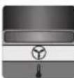
The air flow and temperature can be regulated; normal and programming operation are possible.
When changing from the cool-air stage to the hot-air stage, the air flow, temperature and possibly the program are automatically adjusted according to the settings of the last hot-air stage operation.
Programming Operation
In programming operation, it is possible to continuously store the air-flow and temperature adjustments in four programs. Each program allows for different air-flow and temperature combinations.
In programming operation, it is also possible to change the air flow and temperature any time. When the changes are not saved, they are lost after switching off or changing to a different program.
To change to programming operation, press the program-selection button 6 until the number of the requested program is indicated in the display 7.
The following four programs are preset in the condition of delivery:
| Program | Application | Temperature in °C | Air Flow |
| 1 Deforming plastic tubing (e.g. LDPE) 250 | |
| 2 Welding plastic (e.g. PVC) 350 | |
| 3 Removing Varnish/Softening Adhesives 450 | |
| 4 Soldering 550 |
To change a set program, switch to this program by pressing the program-selection button 6. Set the requested air flow and temperature with the air-flow control button 8 and the temperature-control button 9.
As soon as the settings of a program have been changed, the symbol flashes in the left top of the display. Once the requested air flow and temperature are set, press the save button 10 until the symbol in the display goes out. The set values are now stored under the program number indicated in the display.
Normal Operation
To switch from programming operation to normal operation, press the program-selection button 6 as often as required until no program number is indicated above the temperature in the display. The air flow and temperature can be changed anytime with the air-flow control button 8 and the temperature-control button 9.
Under the following conditions, the values for air flow and temperature set in normal operation will remain stored:
- When changing to programming operation,
- When changing to the cool-air stage,
- When switching the power tool off.
Working Advice
▶ Before any work on the machine itself, pull the mains plug.
Note: Do not apply the nozzle 4 too close to the workpiece being worked. The hot air build-up can lead to overheating of the power tool.
Removing the Heat Protection
The heat protection collar 5 can be removed when working at particularly hard-to-reach locations.
▶ Be careful of the hot nozzle! Increased danger of burning exists when working without the heat protection collar.
To remove or mount the heat protection collar 5, switch the power tool off and allow it to cool down.
To cool down the power tool more quickly, you can operate it for a few moments in the cool-air stage.
Turn the heat protection collar 5 in anticlockwise direction to remove and in clockwise direction to mount again.
English | 15
Placing Down the Power Tool (see figure C)
To cool down the power tool or have both hands free, place it down on the standing surface 1.
▶ Be especially careful when working with the placed down power tool! There is danger of burning oneself on the hot nozzle or on the hot air jet.
Work Examples
The illustrations of the work examples can be found on the fold-out pages.
The temperature settings in the work examples are reference values that can vary, depending on the material characteristics. The distance between the nozzle and the workpiece depends on the material to be worked.
The optimal temperature for the respective application can be determined by practical testing. Always start with a low temperature setting.
All application examples can be performed without accessories except for "Removing Varnish/Paint from Windows". However, the use of recommended accessories simplifies the work and significantly improves the quality of the result.
▶ Be careful when changing the nozzle! Do not touch the hot nozzle. Allow the power tool to cool down and wear protective gloves while changing the nozzle. Danger of burning oneself on the hot nozzle.
Removing Varnish/Softening Adhesives (see figure A)
Mount the wide jet nozzle 11 (accessory). Briefly soften the varnish applying hot air and remove it using a sharp, clean scraper or putty knife. Applying heat too long will burn the varnish, making it more difficult to remove.
Many adhesives (e.g. of stickers) become soft when heated. Heated adhesives allow for bonds to be separated or excessive adhesive to be removed.
Removing Varnish/Paint from Windows (see figure B)
▶ Use of the glass protection nozzle 12 (accessory) is essential. Danger of glass breaking.
On profiled surfaces, varnish can be removed using an appropriately fitting spatula and brushed off with a soft wire brush.
Shaping Plastic Tubing (see figure C)
Mount the reflector nozzle 13 (accessory). To avoid kinking of the tubing, fill the tubing with sand and plug both ends. Heat the tubing evenly by applying the heat from side to side.
Welding Plastics (see figure D)
Mount the reduction nozzle 16 and the welding shoe 15 (both accessories). The workpieces to be welded and the welding rod 14 (accessory) must be of the same material (e.g. both of PVC). The seam must be clean and grease-free.
Carefully heat up the seam location until it becomes doughy. Please note that the temperature difference between the doughy and liquid state of plastic is low.
Feed in the welding rod 14 and allow it to run into the gap so that a uniform bead is produced.
Shrinking (see figure E)
Mount the reduction nozzle 16 (accessory). Select the diameter of the heat-shrinkable sleeve 17 (accessory) according to the workpiece (e.g. a cable lug). Heat the heat-shrinkable sleeve evenly.
Defrosting Water Pipes (see figure F)
▶ Before heating pipes, check to make sure that it is actually a water pipe. Water lines often do not differ in appearance from gas lines. Gas lines are not to be heated under any circumstances.
Place on the angle nozzle 18 (accessory). Heat the frozen zone always from the outside to the middle.
Heat up plastic pipes as well as connections between pipe pieces especially careful to prevent damage.
Soft Soldering (see figure G)
For point soldering, place on the reduction nozzle 16, for the soldering of pipes/tubing, place on the reflector nozzle 13 (both accessories).
If solder without flux is used, apply soldering grease or paste to the location to be soldered. Warm the location to be soldered for 50–120 seconds depending on the material. Apply the solder. The solder must melt from the workpiece temperature. After the soldered location has cooled, remove the flux.
Maintenance and Service
Maintenance and Cleaning
▶ Before any work on the machine itself, pull the mains plug.
For safe and proper working, always keep the machine and ventilation slots clean.
If the replacement of the supply cord is necessary, this has to be done by Bosch or an authorized Bosch service agent in order to avoid a safety hazard.
Cleaning the Coarse-debris Filter
Pull the cover with coarse-debris filter 2 toward the rear out of the housing. Blow out the filter (e.g. with compressed-air) or clean it with a soft brush. Reattach the cover with coarse-debris filter.
If the machine should fail despite the care taken in manufacturing and testing procedures, repair should be carried out by an after-sales service centre for Bosch power tools.
In all correspondence and spare parts order, please always include the 10-digit article number given on the type plate of the machine.
After-sales Service and Customer Assistance
Our after-sales service responds to your questions concerning maintenance and repair of your product as well as spare parts. Exploded views and information on spare parts can also be found under:
www.bosch-pt.com
Our customer service representatives can answer your questions concerning possible applications and adjustment of products and accessories.





16 | English
Great Britain
Robert Bosch Ltd. (B.S.C.)
P.O. Box 98
Broadwater Park
North Orbital Road
Denham
Uxbridge
UB 9 5HJ
Tel. Service: +44 (0844) 736 0109
Fax: +44 (0844) 736 0146
E-Mail: boschservicecentre@bosch.com
Ireland
Origo Ltd.
Unit 23 Magna Drive
Magna Business Park
City West
Dublin 24
Tel. Service: +353 (01) 4 66 67 00
Fax: +353 (01) 4 66 68 88
Australia, New Zealand and Pacific Islands
Robert Bosch Australia Pty. Ltd.
Power Tools
Locked Bag 66
Clayton South VIC 3169
Customer Contact Center
Inside Australia:
Phone: +61 (01300) 307 044
Fax: +61 (01300) 307 045
Inside New Zealand:
Phone: +64 (0800) 543 353
Fax: +64 (0800) 428 570
Outside AU and NZ:
Phone: +61 (03) 9541 5555
www.bosch.com.au
Republic of South Africa
Customer service
Hotline: +27 (011) 6 51 96 00
Gauteng - BSC Service Centre
35 Roper Street, New Centre
Johannesburg
Tel.: +27 (011) 4 93 93 75
Fax: +27 (011) 493 01 26
E-Mail: bsctools@icon.co.za
KZN - BSC Service Centre
Unit E, Almar Centre
143 Crompton Street
Pinetown
Tel.: +27 (031) 7 01 21 20
Fax: +27 (031) 7 01 24 46
E-Mail: bsc.dur@za.bosch.com
Western Cape - BSC Service Centre
Democracy Way, Prosperity Park
Milnerton
Tel.: +27 (021) 5 51 25 77
Fax: +27 (021) 5 51 32 23
E-Mail: bsc@zsd.co.za
Bosch Headquarters
Midrand, Gauteng
Tel.: +27 (011) 6 51 96 00
Fax: +27 (011) 6 51 98 80
E-Mail: rbsa-hq.pts@za.bosch.com
People's Republic of China
China Mainland
Bosch Power Tools (China) Co., Ltd.
567, Bin Kang Road
Bin Jiang District 310052
Hangzhou, P.R.China
Service Hotline: 400 826 8484
Fax: +86 571 8777 4502
E-Mail: contact.ptcn@cn.bosch.com
www.bosch-pt.com.cn
HK and Macau Special Administrative Regions
Robert Bosch Hong Kong Co. Ltd.
21st Floor, 625 King's Road
North Point, Hong Kong
Customer Service Hotline: +852 2101 0235
Fax: +852 2590 9762
E-Mail: info@hk.bosch.com
www.bosch-pt.com.hk
Indonesia
PT. Multi Mayaka
Kawasan Industri Pulogadung
Jalan Rawa Gelam III No. 2
Jakarta 13930
Indonesia
Tel.: +62 (21) 46 83 25 22
Fax: +62 (21) 46 82 86 45/68 23
E-Mail: sales@multimayaka.co.id
www.bosch-pt.co.id
Philippines
Robert Bosch, Inc.
28th Floor Fort Legend Towers,
3rd Avenue corner 31st Street,
Fort Bonifacio Global City,
1634 Taguig City, Philippines
Tel.: +63 (2) 870 3871
Fax: +63 (2) 870 3870
matheus.contiero@ph.bosch.com
www.bosch-pt.com.ph
Bosch Service Center:
9725-27 Kamagong Street
San Antonio Village
Makati City, Philippines
Tel.: +63 (2) 899 9091
Fax: +63 (2) 897 6432
rosalie.dagdagan@ph.bosch.com



Français | 17
Malaysia
Robert Bosch (S.E.A.) Sdn. Bhd.
No. 8A, Jalan 13/6
G.P.O. Box 10818
46200 Petaling Jaya
Selangor, Malaysia
Tel.: +60 (3) 7966 3194
Fax: +60 (3) 7958 3838
cheehoe.on@my.bosch.com
Toll-Free: 1800 880 188
www.bosch-pt.com.my
Thailand
Robert Bosch Ltd.
Liberty Square Building
No. 287, 11 Floor
Silom Road, Bangrak
Bangkok 10500
Tel.: +66 (2) 6 31 18 79 - 18 88 (10 lines)
Fax: +66 (2) 2 38 47 83
Robert Bosch Ltd., P. O. Box 2054
Bangkok 10501, Thailand
Bosch Service – Training Centre
2869-2869/1 Soi Ban Kluay
Rama IV Road (near old Paknam Railway)
Prakanong District
10110 Bangkok
Thailand
Tel.: +66 (2) 6 71 78 00 - 4
Fax: +66 (2) 2 49 42 96
Fax: +66 (2) 2 49 52 99
Singapore
Robert Bosch (SEA) Pte. Ltd.
11 Bishan Street 21
Singapore 573943
Tel.: +65 6571 2772
Fax: +65 6350 5315
leongheng.leow@sg.bosch.com
Toll-Free: 1800 333 8333
www.bosch-pt.com.sg
Vietnam
Robert Bosch Vietnam Co. Ltd
10/F, 194 Golden Building
473 Dien Bien Phu Street
Ward 25, Binh Thanh District
84 Ho Chi Minh City
Vietnam
Tel.: +84 (8) 6258 3690 ext. 413
Fax: +84 (8) 6258 3692
hieu.lagia@vn.bosch.com
www.bosch-pt.com
Disposal
The machine, accessories and packaging should be sorted for environmental-friendly recycling.
Do not dispose of power tools into household waste!
Only for EC countries:
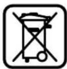
According to the European Guideline 2002/96/EC for Waste Electrical and Electronic Equipment and its implementation into national right, power tools that are no longer usable must be collected separately and disposed of in an environmentally correct manner.
Subject to change without notice.
Français
Robert Bosch (France) S.A.S.
Bosch Service Center
Telegrafvej 3
2750 Ballerup
Tlf. Service Center: +45 (4489) 8855
Fax: +45 (4489) 87 55
E-Mail: vaerktoej@dk.bosch.com
Bortskaffelse
Bosch Service Center
Telegrafvej 3
2750 Ballerup
Danmark
Tel.: +46 (020) 41 44 55
Fax: +46 (011) 18 76 91
Avfallshantering
Bosch San. ve Tic. A.S.
Ahi Evran Cad. No:1 Kat:22
Polaris Plaza
80670 Maslak/Istanbul
Bosch Uzman Ekibi +90 (0212) 367 18 88
Işıklar LTD.ŞTİ.
Kızılay Cad. No: 16/C Seyhan
Adana
Tel.: 0322 359 97 10
Tel.: 0322 359 13 79
Robert Bosch Sp. z o.o.
Bosch Service Center PT
K Vápence 1621/16
692 01 Mikulov
Tel.: +420 (519) 305 700
Fax: +420 (519) 305 705
E-Mail: servis.naradi@cz.bosch.com
www.bosch.cz
Zpracování odpadů

- GHG 660 LCD Professional
- BOSCH
- Deutsch | 7
- Deutsch
- Sicherheitshinweise
- | English
- Product Description and Specifications
- Intended Use
- Product Features
- Noise Information
- Operation
- Starting Operation
- Switching On and Off
- Regulating the Air flow
- Setting the Temperature
- Activating/Deactivating the Button Lock ("LOC")
- Activating the Button Lock:
- | English
- Deactivating the Button Lock:
- Operating Modes
- Cool-air Stage
- Hot-air Stage
- Programming Operation
- Normal Operation
- Working Advice
- Removing the Heat Protection
- English | 15
- Placing Down the Power Tool (see figure C)
- Work Examples
- Removing Varnish/Softening Adhesives (see figure A)
- Removing Varnish/Paint from Windows (see figure B)
- Shaping Plastic Tubing (see figure C)
- Welding Plastics (see figure D)
- Shrinking (see figure E)
- Defrosting Water Pipes (see figure F)
- Soft Soldering (see figure G)
- Maintenance and Service
- Maintenance and Cleaning
- Cleaning the Coarse-debris Filter
- After-sales Service and Customer Assistance
- www.bosch-pt.com
- | English
- Great Britain
- Ireland
- Australia, New Zealand and Pacific Islands
- Republic of South Africa
- Customer service
- Gauteng - BSC Service Centre
- KZN - BSC Service Centre
- Western Cape - BSC Service Centre
- Bosch Headquarters
- People's Republic of China
- China Mainland
- HK and Macau Special Administrative Regions
- Indonesia
- Philippines
- Malaysia
- Thailand
- Singapore
- Vietnam
- Disposal
- Only for EC countries:
- Français
- Bortskaffelse
- Avfallshantering
- Zpracování odpadů
Brand : BOSCH
Model : GHG 660 LCD
Category : Heat gun