WMN460UTD - Flat screen mount SAMSUNG - Free user manual and instructions
Find the device manual for free WMN460UTD SAMSUNG in PDF.

User questions about WMN460UTD SAMSUNG
0 question about this device. Answer the ones you know or ask your own.
Ask a new question about this device
Download the instructions for your Flat screen mount in PDF format for free! Find your manual WMN460UTD - SAMSUNG and take your electronic device back in hand. On this page are published all the documents necessary for the use of your device. WMN460UTD by SAMSUNG.
USER MANUAL WMN460UTD SAMSUNG
| Safety Precautions | 01 | Safety | Precautions | |
| Introduction | 02 | Unpacking | ||
| 02 Attaching the bracket | a to the monitor | |||
| 03 Mounting the bracket | b onto a wall | |||
| 06 Arranging the monitors | 07 | Fine | tuning | |
| 10 Detaching the monitors | ||||
| Product specifications | 11 | Product specifications | ||
| Product drawings | 12 | Product drawings | ||
| 13 | Drawings | |||
Safety Precautions
The information contained herein is for your safety and to prevent any loss of property. Please read the instructions carefully to use the product correctly.
⚠ Warning
Failure to observe the instructions herein can cause serious injury or death.
This mandatory sign is used to emphasize the instructions that must be observed.
- Be sure to contact an installation expert authorized by your dealer to perform the installation.
• Installation by a non-professional may cause personal injury.
If you are planning to relocate or replace the product after installation, be sure to consult with an installation expert authorized by your dealer.

natural_image
Illustration of two people: one holding a book and the other listening to a smartphone with 'AS' logo (no text or symbols on subjects)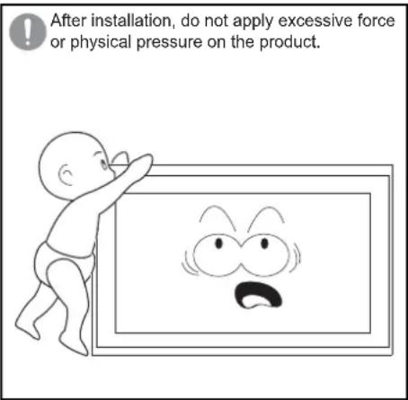
text_image
After installation, do not apply excessive force or physical pressure on the product.- Do not let your children play in the vicinity of the product.
- They may bump their head or body against the corner of the product and suffer personal injury.
- Be careful not to let the back of the product hit against the wall when it is rotated or the angle is adjusted.
- You can protect the wall and product from any damage by attaching a piece of sponge to each corner of the product.
- Do not install the product on a wall that cannot bear the weight of the product.
- The product may fall, and get damaged or cause personal injury.
- Products installed in unusual, abnormal or extreme areas may be subject to serious performance problems due to the surrounding environment. Be sure to consult with a Samsung service center before installing the product in such an area.
- Areas exposed to an excessive amount of fine particles or moisture, chemicals, extreme temperatures, high humidity, automobiles, etc.
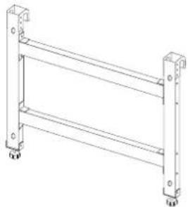
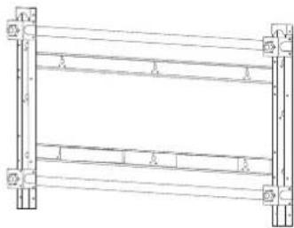
Unpacking
natural_image
Technical line drawing of a metal ladder structure with mounting feet (no text or symbols)Monitor-mount bracket ⓐ
natural_image
Pure structural diagram of a frame with supports and beams, no text or symbols presentWall-mount bracket ⑥
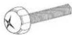
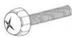
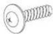
Screw @
(M8 X 60mm) : x4
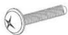
Screw ⓑ
(M8 X 30mm) : x4
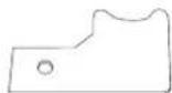
Coupler : x2 Screw holder: x4

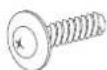
Wood screw (M5 X 50mm) : x8
Safety fastener: x2

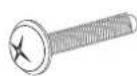
Screw ©
(M5 X 10mm) : x2
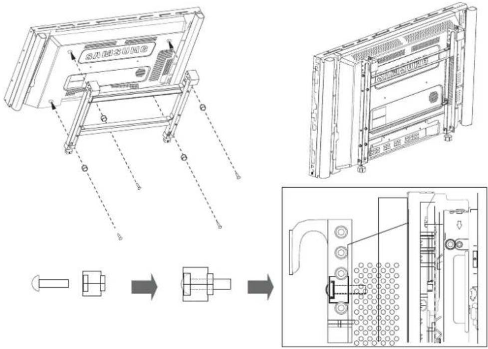
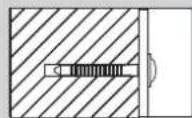
Attaching the bracket ⓐ to the monitor
- Assemble the four screws ⓐ and the screw holders, and fasten them to fix the bracket ⓐ to the monitor as shown in the picture below.
text_image
SAMSUNG▲ Warning
Check to confirm that the bracket ⓐ is fastened to the monitor.
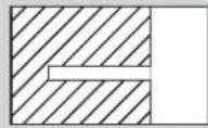
Mounting the bracket ⑥ onto a wall
- Fix the bracket ⓑ tightly against the wall using the wood screws.

text_image
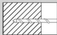
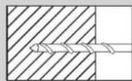
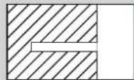
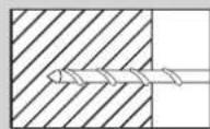
Technical diagram of a structural frame with numbered components and lighting fixtures※ How to fasten a screw
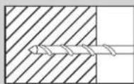
Make a hole using a 3X50 drill.

Clean the inside of the drilled hole.

Fasten the wood screw into the hole.
※ When drilling a hole into a wall, make sure you use a drill bit and drill of the specified diameter. Otherwise, there may be safety problems.
Warning
-
Ensure you check the wall strength, and do the reinforcing work before installation if the wall is not sufficiently strong.
-
The provided screws are for wood.
-
Check the wall and use proper screws according to the material of the wall, such as marble, steel plate or concrete.
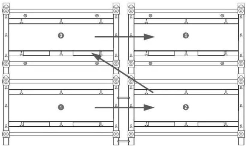
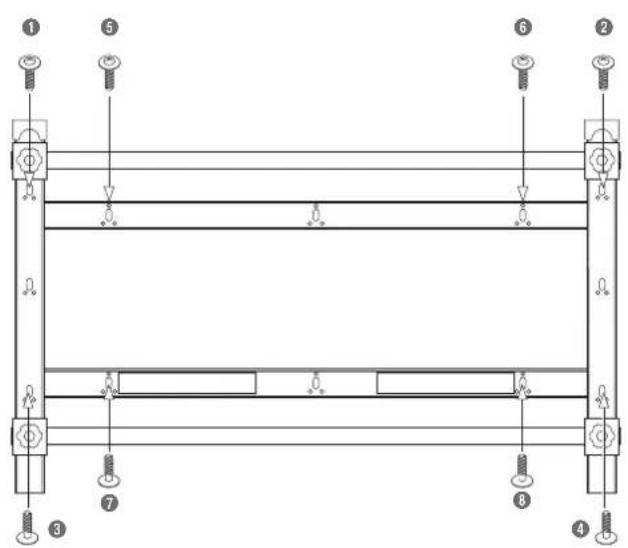
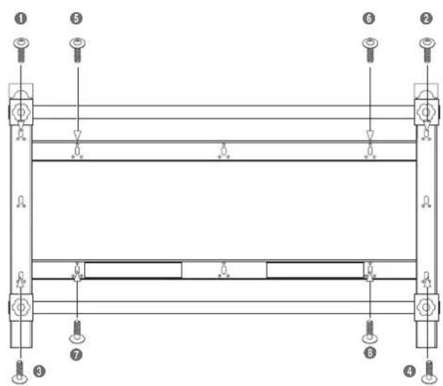
As shown in the picture above, fasten in order from ① to ⑧.
If it is difficult to fasten the screws into the specific holes, fasten the screws in the adjacent holes.
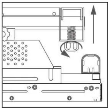
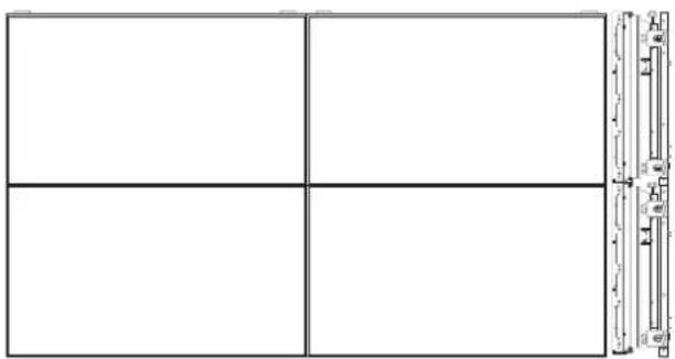
☆ Installing the Video Wall
text_image
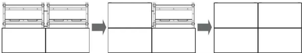
Technical diagram showing labeled structural components with numbered annotations and directional arrows indicating movement or flow.Installing the Video Wall should be done by two persons or more.
The couplers are only used to install a Video Wall in order to leave a gap between the monitors that make up the Video Wall. Do not use them when installing only one monitor.
▲ Warning
- Before you install on the Video Wall, check the wall strength considering the total weight of the monitors and brackets you want to install.
- Weight of a monitor: 30kg
- Weight of a bracket: 7kg
-
If you intend to install on a Video Wall that is four layers or more, take into consideration the air conditioning system. Consult with an expert before installation as heat from the monitors may cause problems.
-
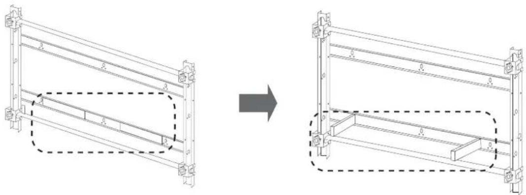
Fix the two couplers into the middle and lower parts of the bracket ⑥ respectively.
Fasten the two screws ⓑ into the bracket ⓑ.
natural_image
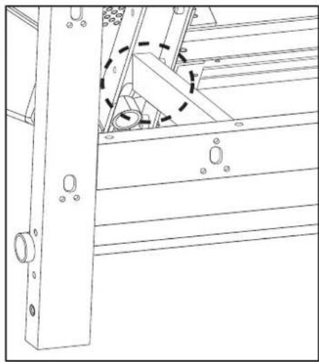
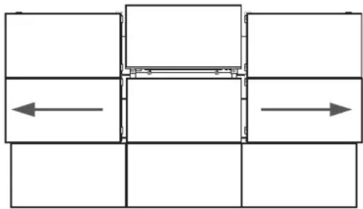
Technical diagram showing a mechanical assembly with a detailed close-up view of a shaft and housing (no text or symbols present)- To align horizontally, attach the bracket ② to the couplers on the bracket ① using the screws ⑥.
(Should be done by two persons or more.)
After fixing tightly, attach the assembly to the wall following step 1.
Fasten the screws tightly so that there is no space between the couplers and the bracket ⑥.
natural_image
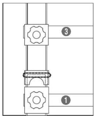
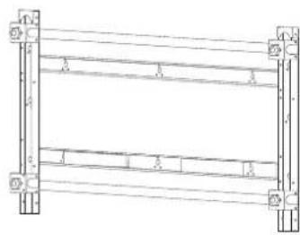
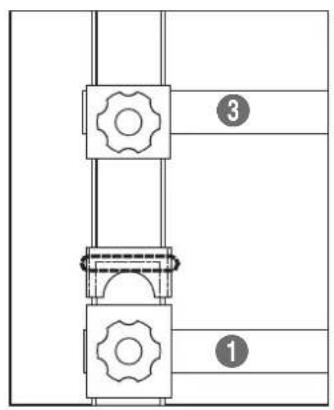
Pure structural diagram of two vertical beams with mounting holes and directional arrows, no text or symbols present- To align vertically, insert the legs of the bracket ③ completely to the top of the bracket ① to assemble the two brackets.
natural_image
Technical line drawing of a multi-level structural frame with mounting holes and supports (no text or symbols)
flowchart
graph TD
    A["Step 1"] --> B["Step 2"]
    B --> C["Step 3"]

text_image
③ ①▲ Warning
As shown in the pictures, the bottom of the bracket ③ must be inserted fully into the top of the bracket ①.
- Following steps 2 to 4, fix the bracket to the location ④.
natural_image
Pure architectural or structural diagram of a multi-level building frame with horizontal beams and corner supports (no text or symbols)Increase the number of brackets following the steps above.
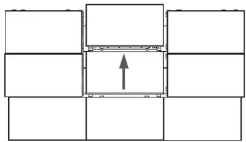
Arranging the monitors
- Hook the monitor to which the bracket ⓐ is attached on the poles of the wall-mount bracket ⓑ.
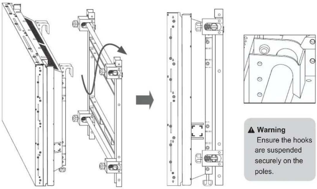
▲ Warning
Ensure the hooks are suspended securely on the poles.
⚠ Warning
Be sure not to put pressure on the panel with your hands when handling the monitor. Otherwise, you may break the panel.
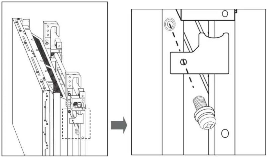
- To prevent the monitor from becoming loose, fasten the safety fasteners using the screws ©. Fasten them on both sides.
natural_image
Technical line drawing of a mechanical assembly before and after modification, showing structural components and a bolted component (no text or symbols)⚠ Warning
Since the monitor may fall during installation, ensure you fasten the safety fasteners on both sides.
natural_image
Technical line drawing of a mechanical assembly with rollers and components (no text or symbols)
natural_image
Technical line drawing of a mechanical assembly with no visible text or symbols
natural_image
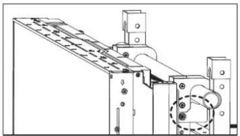
Pure architectural or engineering line drawing of structural beams and supports without any text, numbers, or symbols- Arrange the monitor on each bracket following steps 1 and 2.
flowchart
graph LR
    A["Initial Assembly"] --> B["Intermediate Processing"]
    B --> C["Final Grid State"]
⚠ Warning
Be careful not to catch your finger during installation.
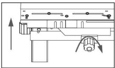
Fine tuning
natural_image
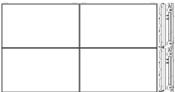
Pure grid layout with four empty cells and a vertical scale bar on the right (no text or symbols)☑ After arranging the monitors, if they do not seem well-proportioned, adjust them using the fine-tuning screws on the brackets.
☑ Be sure not to leave any height differences or gaps between the monitors.
- Correcting height difference between the front and back of a monitor.
If you turn the fine-tuning screw clockwise or counterclockwise, the monitor will move forward or backward respectively.
The fine-tuning screw's maximum movement range is 10mm.
Moving the monitor forward
natural_image
Technical line drawing of a mechanical assembly with no visible text or symbolsMoving the monitor backward
natural_image
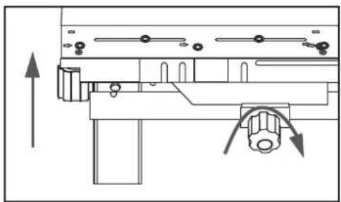
Technical line drawing of a mechanical device with internal components and directional arrows (no text or symbols)- Correcting height difference between upper and lower monitors.
If you turn the fine-tuning screw on the bottom of the monitor clockwise or counterclockwise, the monitor will move up or down respectively.
natural_image
Pure technical diagram of a mechanical assembly with two vertical arrows indicating upward motion, no text or symbols present.Lowering the monitorRaising the monitor
natural_image
Technical diagram of a mechanical assembly with directional arrows indicating movement (no text or labels)
natural_image
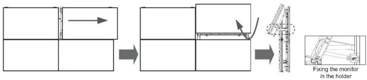
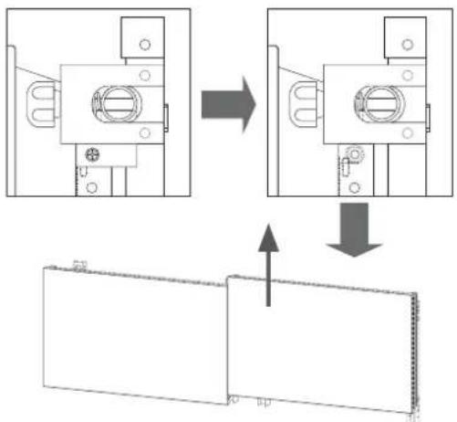
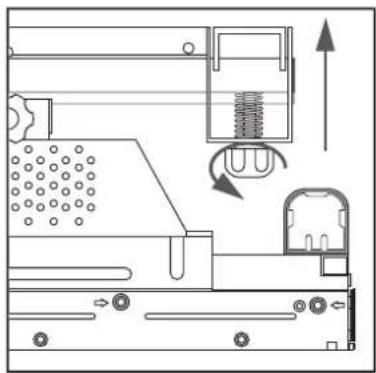
Technical diagram of a mechanical assembly with directional arrows indicating movement or force (no text or symbols present)☆ To adjust the height difference between the monitors on the upper layer,
① Move a monitor until a space large enough to accommodate your hand is created.
② Rotate the monitor, unfold the holder attached to the bracket and fix the monitor in the holder.
③ Turn the fine-tuning screw to correct the height difference.
④ Repeat steps ①\~③ till you obtain the optimum result.
flowchart
graph LR
    A["Initial Component"] --> B["Step 1: Inspection"]
    B --> C["Step 2: Assembly"]
    C --> D["Step 3: Case with Contour"]
    D --> E["Final Setup: Fixing the monitor in the holder"]
natural_image
Technical line drawing showing structural components before and after assembly (no text or symbols)⚠ Warning
- Be careful not to catch your fingers.
- Ensure the holder is fastened to the monitor-mount bracket ⑥.
natural_image
Technical line drawing of a mechanical assembly with no visible text or symbolsDetaching the monitors
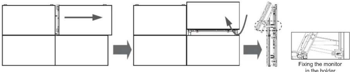
1. Detaching the upper monitors
Unfasten the screws fixing the safety fasteners and lift up the monitors from the video wall.
text_image
Technical diagram showing assembly steps of a mechanical component with directional arrows indicating process flow.Caution
Before detaching the monitors, ensure you disconnect all the cables connected to them.
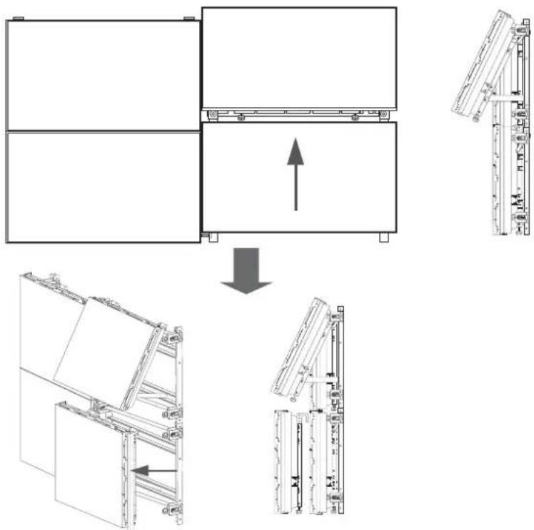
2. Detaching the lower monitors
① Move the monitor you want to detach, and rotate and fix it in the holder.
flowchart
graph LR
    A["Assembly"] --> B["Adjustment"]
    B --> C["Assembly"]
    C --> D["Fixing the monitor in the holder"]
② Remove the safety fasteners from the monitor and lift up the monitor to detach it from the video wall as shown in the picture below.
flowchart
graph TD
    A["Structural Component A"] --> B["Assembly"]
    B --> C["Component B"]
    C --> D["Assembly"]
    D --> E["Component C"]
    E --> F["Assembly"]
    style A fill:#f9f,stroke:#333
    style B fill:#ccf,stroke:#333
    style C fill:#cfc,stroke:#333
    style D fill:#fcc,stroke:#333
    style E fill:#cff,stroke:#333
    style F fill:#ffc,stroke:#333
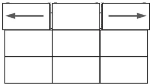
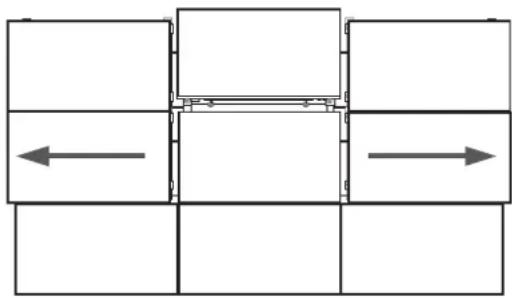
- Detaching the middle monitor from 3X3 Video Wall

flowchart
graph TD
    A[" "] --> B[" "]
    B --> C[" "]
    D[" "] --> E[" "]
    E --> F[" "]
    G[" "] --> H[" "]
    H --> I[" "]
- Move the left and right monitors on the top layer until a space large enough to accommodate your hand is created.


flowchart
graph TD
    A[" "] --> B[" "]
    B --> C[" "]
    C --> D[" "]
    D --> E[" "]
    E --> F[" "]
    F --> G[" "]
    G --> H[" "]
    H --> I[" "]
    I --> J[" "]
    J --> K[" "]
    K --> L[" "]
    L --> M[" "]
    M --> N[" "]
    N --> O[" "]
    O --> P[" "]
    P --> Q[" "]
    Q --> R[" "]
    R --> S[" "]
    S --> T[" "]
    T --> U[" "]
    U --> V[" "]
    V --> W[" "]
    W --> X[" "]
    X --> Y[" "]
    Y --> Z[" "]


natural_image
Pure mechanical assembly diagram showing four rectangular blocks with internal components and directional arrows, no text or symbols present.-
Rotate the middle monitor to fix it in the holder.
-
Move the left and right monitors on the middle layer following step 1.

natural_image
Pure architectural floor plan lines without any text, numbers, or symbols
- Lift up the middle monitor to detach it from the video wall.
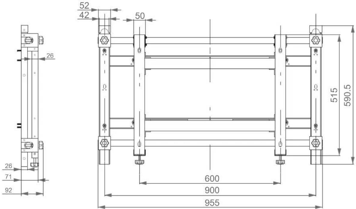
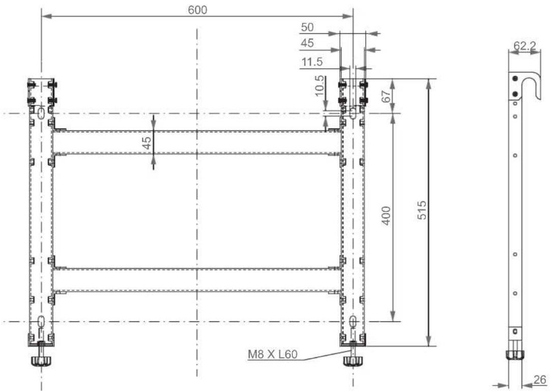
Product specifications
| Dimensions (mm) W955 X H590.5 | X D93 |
| Weight (kg) 7 | |
| VESA standard wall-mount (mm) | 600 X 400 |
Caution
For performance improvement, the product's exterior and specifications are subject to change without prior notice.
Product drawings
text_image
26 71 92 52 42 50 0 600 900 955 515 590.5
text_image
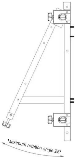
Maximum rotation angle 25°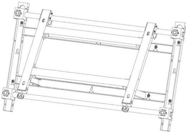
natural_image
Technical line drawing of a mechanical frame structure with mounting holes and supports (no text or symbols)Drawings
1. Monitor-mount bracket ⓐ

2. Wall-mount bracket ⓑ

Sommaire
natural_image
Technical line drawing of a metal ladder structure with mounting feet (no text or symbols)
natural_image
Pure structural diagram of a frame with supports and beams, no text or symbols presenttext_image
Technical diagram of a structural frame with numbered components and support symbolstext_image
Technical diagram showing labeled structural components with numbered annotations and directional arrows indicating movement or flow.natural_image
Technical diagram showing a mechanical assembly with a detailed close-up view of a shaft and housing (no text or symbols present)natural_image
Pure structural diagram of two vertical beams with bolt holes, no text or symbols presentnatural_image
Technical line drawing of a multi-level structural frame with mounting holes and supports (no text or symbols)Français - 4

flowchart
graph TD
    A["Step 1"] --> B["Step 2"]
    B --> C["Step 3"]

text_image
③ ①Avertissement
natural_image
Pure architectural or structural diagram of a multi-level building frame with horizontal beams and corner supports (no text or symbols)natural_image
Technical line drawing of a mechanical assembly before and after modification, showing structural components and a bolted component (no text or symbols)Avertissement
flowchart
graph LR
    A["Rectangular Block with Horizontal Bars"] --> B["Divided into two horizontal bars"]
    B --> C["Grid with four empty cells"]
Avertissement
natural_image
Pure grid layout with four quadrants and vertical measurement indicators (no text or symbols)natural_image
Technical line drawing of a mechanical assembly with no visible text or symbolsnatural_image
Technical line drawing of a mechanical assembly with no visible text or symbolsnatural_image
Pure technical diagram of a mechanical assembly with two vertical arrows indicating upward motion, no text or symbols present.natural_image
Technical diagram of a mechanical assembly with directional arrows indicating movement (no text or symbols)natural_image
Technical diagram of a mechanical assembly with directional arrows indicating movement or force (no text or symbols present)natural_image
Technical line drawing of a mechanical assembly with no visible text or symbolsnatural_image
Technical diagram showing a mechanical assembly before and after transformation, with no visible text or symbols.Attention
flowchart
graph LR
    A["Grid with left and center cell"] --> B["Grid with right arrow and left arrow, right arrow"]
flowchart
graph LR
    A["Step 1: Top-Left Block with curved arrow indicating motion"] --> B["Step 2: Left Side Block with horizontal arrows indicating direction"]
    B --> C["Right Side Block with horizontal arrows indicating direction"]
natural_image
Architectural floor plan diagram showing room layout and structural elements (no text or labels)natural_image
Technical line drawing of a mechanical frame structure with mounting holes and supports (no text or symbols)natural_image
Technical line drawing of a metal ladder structure with mounting feet (no text or symbols)natural_image
Pure structural diagram of a frame with supports and beams, no text or symbols present
text_image
Technical diagram of a mechanical or structural assembly with numbered components and support symbolstext_image
Technical diagram showing three labeled structural components (1, 2, 3) with directional arrows indicating movement or flow.Achtung
natural_image
Technical diagram showing a mechanical assembly with a detailed close-up view of a shaft and housing (no text or symbols present)natural_image
Pure structural diagram of two vertical beams with mounting holes and directional arrows, no text or symbols presentnatural_image
Technical line drawing of a structural frame assembly with supports and mounting holes (no text or symbols)
flowchart
graph TD
    A["Step 1"] --> B["Step 2"]
    B --> C["Step 3"]

text_image
③ ①Achtung
natural_image
Pure architectural or structural diagram of a multi-level building frame with horizontal beams and corner supports (no text or symbols)natural_image
Technical line drawing of a mechanical assembly before and after modification, showing structural components and a bolted component (no text or symbols)Achtung
flowchart
graph LR
    A["Structural assembly with horizontal members"] --> B["Vertical alignment"]
    B --> C["Grid alignment"]
Achtung
natural_image
Pure geometric diagram with four quadrants and vertical line segments (no text or symbols)natural_image
Technical diagram of a mechanical assembly with labeled components and directional arrows (no text or symbols)natural_image
Technical line drawing of a mechanical device with internal components and directional arrows (no text or symbols)natural_image
Pure technical diagram of a mechanical assembly with two vertical arrows indicating upward motion, no text or symbols present.natural_image
Technical diagram of a mechanical assembly with directional arrows indicating movement (no text or labels)
natural_image
Technical diagram of a mechanical assembly with directional arrows indicating movement or force (no text or symbols present)natural_image
Technical line drawing showing structural components before and after assembly (no text or symbols)Achtung
natural_image
Technical line drawing of a mechanical assembly with no visible text or symbolsflowchart
graph LR
    A["Grid with left and center cell"] --> B["Grid with right arrow and left side, right side with right arrow"]
flowchart
graph LR
    A["Before modification"] --> B["Structural change with curved arrow indicating motion"]
    B --> C["After modification with leftward and rightward arrows indicating movement"]
natural_image
Architectural floor plan diagram showing structural layout with a directional arrow and a 3D vertical scale (no text or labels)natural_image
Technical line drawing of a mechanical frame structure with mounting holes and supports (no text or symbols)Zeichnungen
natural_image
Technical line drawing of a metal ladder structure with mounting feet (no text or symbols)text_image
Technical diagram of a structural frame with numbered components and support symbolstext_image
Technical diagram showing labeled structural components with numbered annotations and directional arrows indicating movement or flow.natural_image
Technical diagram showing a mechanical assembly with a detailed close-up view of a shaft and housing (no text or symbols present)natural_image
Pure structural diagram of two vertical supports with horizontal beams and support columns, no text or symbols presentnatural_image
Technical line drawing of a structural frame assembly with vertical supports and horizontal beams (no text or symbols)
flowchart
graph TD
    A["Step 1"] --> B["Step 2"]
    B --> C["Step 3"]

text_image
③ ①Figyelem
natural_image
Pure architectural or structural diagram of a multi-level building frame with horizontal beams and corner supports (no text or symbols)natural_image
Technical line drawing of a mechanical assembly before and after modification, showing structural components and a close-up view (no text or symbols)Figyelem
flowchart
graph LR
    A["Initial Assembly"] --> B["Intermediate Processing"]
    B --> C["Final Grid State"]
Figyelem
natural_image
Pure grid layout with four empty cells and a vertical line diagram on the right (no text or symbols)natural_image
Technical line drawing of a mechanical assembly with no visible text or symbolsnatural_image
Technical line drawing of a mechanical assembly with no visible text or symbolsnatural_image
Pure mechanical diagram showing two vertical arrows above a horizontal plate with mounting fixtures (no text or symbols)natural_image
Technical diagram of a mechanical assembly with directional arrows and component symbols (no readable text or labels)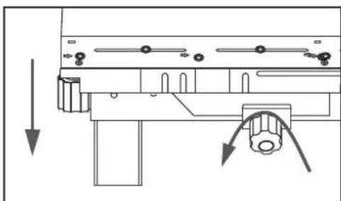
natural_image
Pure mechanical assembly diagram without any text, numbers, or symbolsflowchart
graph TD
    A["Top Panel"] --> B["Side Panel"]
    B --> C["Side Panel with Component"]
    C --> D["Monitor with Radial Strip"]
    D --> E["Tartóelemhez Monitor"]
    E --> F["Bottom Panel with Side View"]
    F --> G["Tartóelemhez Top Panel"]
Figyelem
natural_image
Technical line drawing of a mechanical assembly with no visible text or symbolstext_image
Technical diagram showing assembly steps of a mechanical component with labeled parts and directional arrows indicating process flow.Vigyázat
natural_image
Pure diagram of a mechanical or electrical component with no text, numbers, or symbols

natural_image
Pure diagram of a mechanical or structural assembly with no text, numbers, or symbolsnatural_image
Pure architectural floor plan lines without any text, numbers, or symbols
natural_image
Technical line drawing of a mechanical frame structure with mounting holes and supports (no text or symbols)Rajzok
natural_image
Technical line drawing of a metal ladder structure with mounting feet (no text or symbols)
Vite ©
(M5 X 10mm) : x2
natural_image
Technical line drawing of a server rack unit with ventilation grilles and drive bays (no text or symbols)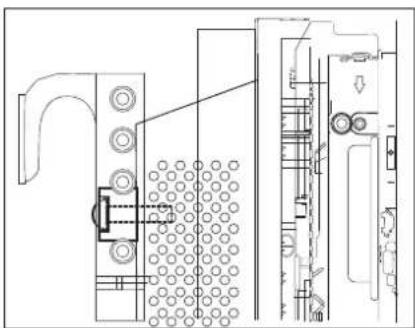
natural_image
Technical line drawing of a mechanical assembly with no visible text or symbolsAvvertenza
text_image
Technical diagram of a mechanical or structural assembly with numbered components and support symbolstext_image
Technical diagram showing three labeled structural components (1, 2, 3) with directional arrows indicating movement or flow.natural_image
Technical line drawing of a mechanical assembly with dimension arrows and cross-section detail (no text or symbols)natural_image
Pure structural diagram of two vertical beams with mounting holes and directional arrows, no text or symbols presentnatural_image
Technical line drawing of a multi-level structural frame with mounting holes and supports (no text or symbols)
flowchart
graph TD
    A["Step 1"] --> B["Step 2"]
    B --> C["Step 3"]

text_image
Technical diagram showing three labeled components (1, 3) with gear symbols and dashed lines indicating alignment or assembly.Avvertenza
natural_image
Pure architectural or structural diagram of a multi-level building frame with horizontal beams and corner supports (no text or symbols)natural_image
Technical line drawing showing a mechanical assembly before and after modification, with no visible text or symbols.Avvertenza
flowchart
graph LR
    A["Initial Assembly"] --> B["Intermediate Processing"]
    B --> C["Final Grid State"]
Avvertenza
natural_image
Pure grid layout with four empty cells and a vertical line diagram on the right (no text or symbols)natural_image
Technical diagram of a mechanical assembly with labeled components and directional arrows (no text or symbols)natural_image
Technical line drawing of a mechanical device with internal components and directional arrows (no text or symbols)natural_image
Pure technical diagram of a mechanical assembly with two vertical arrows indicating upward motion, no text or symbols present.natural_image
Technical diagram of a mechanical assembly with directional arrows indicating movement (no text or labels)
natural_image
Technical diagram of a mechanical assembly with directional arrows indicating movement or force (no text or symbols present)flowchart
graph TD
    A["Assembly"] --> B["Reassembly"]
    B --> C["Assembly with Support Vite"]
    C --> D["Final Assembly with Support Vite"]
    subgraph 'Fissaggio del monitor al supporto vite'
        E["Diagram: Panel 1: Screen with arrow indicating assembly direction"]
        F["Diagram: Panel 2: Panel 1, Panel 3, Panel 4: Panel 1, Panel 2, Panel 3, Panel 4"] --> G["Final Assembly with Support Vite"]
Avvertenza
natural_image
Technical line drawing of a mechanical assembly with no visible text or symbolsnatural_image
Technical diagram showing a mechanical assembly before and after assembly, with no visible text or symbols.Attenzione
flowchart
graph TD
    A["Grid with left and right arrows"] --> B["Rectangular Layout with horizontal and vertical arrows"]
natural_image
Architectural floor plan diagram showing structural layout with a directional arrow and a side-view detail (no text or labels)natural_image
Illustration of a person reading a book while holding a pencil, appearing thoughtful (no text or symbols present)
text_image
AS SAMSUNG
natural_image
Cartoon illustration of a baby pushing a large box with a surprised face (no text or symbols)natural_image
Technical line drawing of a metal ladder structure with mounting feet (no text or symbols)
natural_image
Pure structural diagram of a frame with supports and beams, no text or symbols presenttext_image
Technical diagram of a structural frame with numbered components and lighting fixturestext_image
Technical diagram showing labeled structural components with numbered annotations and directional arrows indicating movement or flow.natural_image
Technical line drawing of a mechanical assembly with an exploded view showing internal components (no text or symbols)natural_image
Pure structural diagram of two identical frame structures with vertical supports and horizontal beams, no text or symbols present.natural_image
Technical line drawing of a structural frame with supports and mounting holes (no text or symbols)
flowchart
graph TD
    A["Step 1"] --> B["Step 2"]
    B --> C["Step 3"]
text_image
③ ①⚠ Ostrzeżenie
natural_image
Pure architectural or structural diagram of a multi-level building frame with horizontal beams and corner supports (no text or symbols)natural_image
Technical line drawing of a mechanical assembly before and after modification, showing structural components and mounting features (no text or symbols)Ostrzeżenie
flowchart
graph LR
    A["Initial Assembly"] --> B["Intermediate Processing"]
    B --> C["Final Grid State"]
Ostrzeżenie
natural_image
Simple grid layout with four empty cells and a vertical line diagram on the right (no text or symbols)natural_image
Technical diagram of a mechanical assembly with labeled components and directional arrows (no text or symbols)natural_image
Technical line drawing of a mechanical device with internal components and directional arrows (no text or symbols)natural_image
Pure technical diagram of a mechanical assembly with two vertical arrows indicating upward motion, no text or symbols present.natural_image
Technical diagram of a mechanical assembly with directional arrows indicating movement (no text or symbols)
natural_image
Pure mechanical assembly diagram without any text, numbers, or symbolsnatural_image
Technical line drawing showing structural assembly before and after modification (no text or symbols)Ostrzeżenie
natural_image
Technical line drawing of a mechanical assembly with no visible text or symbolstext_image
Technical diagram showing assembly steps of a mechanical component with labeled parts and directional arrows indicating process flow.⚠ Uwaga
flowchart
graph LR
    A["Start"] --> B["Step 1: Internal assembly with arrow indicating direction"]
    B --> C["Step 2: Internal assembly with arrow indicating direction"]
    C --> D["Step 3: Internal assembly with arrow indicating direction"]
    D --> E["Zabezpieczanie monitor w obejmie"]
flowchart
graph TD
    A["Grid with left and right arrows"] --> B["Rectangular Layout with horizontal and vertical arrows"]
natural_image
Architectural diagram showing a 3x3 grid layout with an arrow indicating upward movement, alongside a detailed side view of a tower structure (no text or symbols)natural_image
Technical line drawing of a mechanical frame structure with mounting holes and supports (no text or symbols)Schematy
natural_image
Technical line drawing of a metal ladder structure with mounting feet (no text or symbols)
natural_image
Pure structural diagram of a frame with supports and beams, no text or symbols presenttext_image
Technical diagram of a structural frame with numbered components and support fixturestext_image
Technical diagram showing four labeled structural components (1, 2, 3, 4) with directional arrows indicating movement or flow.natural_image
Technical diagram showing a mechanical assembly with two views: top view with arrows indicating direction, bottom view with close-up detail (no text or symbols)- Para alinhar na horizontal, prenda o suporte ② aos acopladores no suporte ① utilizando os parafusos ⑥.
natural_image
Pure structural diagram of two identical frame structures with mounting holes and horizontal beams, no text or symbols present.natural_image
Technical line drawing of a structural frame assembly with supports and mounting holes (no text or symbols)
flowchart
graph TD
    A["Step 1"] --> B["Step 2"]
    B --> C["Step 3"]

text_image
③ ①Aviso
natural_image
Pure architectural or structural line drawing of a multi-level building frame with no text, numbers, or symbolsnatural_image
Technical line drawing of a mechanical assembly before and after modification, showing structural components and mounting features (no text or symbols)Aviso
flowchart
graph LR
    A["Initial Assembly"] --> B["Intermediate Processing"]
    B --> C["Final Grid State"]
Aviso
natural_image
Pure grid layout with four empty cells and a vertical line diagram on the right (no text or symbols)natural_image
Diagram of a computer motherboard showing key components and directional arrows (no text or labels)Deslocar o monitor para trás
natural_image
Technical line drawing of a mechanical device with internal components and directional arrows (no text or symbols)- Corrigir a diferença de altura entre o monitor superior e inferior.
natural_image
Pure technical diagram of a mechanical assembly with two vertical arrows indicating upward motion, no text or symbols present.natural_image
Technical diagram of a mechanical assembly with directional arrows indicating movement (no text or labels)
natural_image
Technical diagram of a mechanical assembly with directional arrows indicating movement or force (no text or symbols present)☆ Para ajustar a diferença de altura entre os monitores da camada superior,
natural_image
Technical line drawing showing structural components before and after assembly (no text or symbols)
Aviso
natural_image
Technical line drawing of a mechanical assembly with no visible text or symbolstext_image
Technical diagram showing assembly steps of a mechanical component with directional arrows indicating process flow.Atenção
flowchart
graph TD
    A["Grid with left and right arrows"] --> B["Grid with left arrow, right arrow"]
flowchart
graph LR
    A["Left Block"] --> B["Right Block"]
    style A fill:#f9f,stroke:#333
    style B fill:#bbf,stroke:#333
    C["Arrow indicates clockwise motion"] --> D["Arrow indicates clockwise motion"]
natural_image
Architectural floor plan showing a 3x4 grid layout with an upward arrow indicating a structural component (no text or labels)natural_image
Illustration of a person reading a book while holding a pencil, appearing thoughtful (no text or symbols present)
text_image
AS SAMSUNG
natural_image
Cartoon illustration of a baby pushing a large screen with a surprised face (no text or symbols)natural_image
Technical line drawing of a metal ladder structure with mounting feet (no text or symbols)natural_image
Pure structural diagram of a frame with supports and beams, no text or symbols presenttext_image
Technical diagram of a structural frame with numbered components and support symbols※ Крепление винта
text_image
Technical diagram showing labeled structural components with numbered annotations and directional arrows indicating movement or flow.natural_image
Technical line drawing of a mechanical assembly with structural components and a close-up view of a gear mechanism (no text or symbols)natural_image
Pure structural diagram of two vertical beams with mounting holes and directional arrows, no text or symbols presentnatural_image
Technical line drawing of a structural frame assembly with supports and mounting holes (no text or symbols)
flowchart
graph TD
    A["Step 1"] --> B["Step 2"]
    B --> C["Step 3"]

text_image
③ ①⚠ Предупреждение
natural_image
Pure architectural or structural line drawing of a multi-level building frame with no text, numbers, or symbolsnatural_image
Technical line drawing of a mechanical assembly before and after modification, showing structural components and mounting features (no text or symbols)▲ Предупреждение
natural_image
Technical line drawing of a mechanical assembly with rollers and components (no text or symbols)
natural_image
Technical line drawing of a mechanical assembly with no visible text or symbols
natural_image
Pure architectural or engineering line drawing of structural beams and supports without any text, numbers, or symbolsflowchart
graph LR
    A["Initial Assembly"] --> B["Intermediate Processing"]
    B --> C["Final Grid State"]
▲ Предупреждение
natural_image
Pure grid layout with four empty cells and a vertical scale bar on the right (no text or symbols)natural_image
Technical line drawing of a mechanical assembly with no visible text or symbolsnatural_image
Technical line drawing of a mechanical device with internal components and directional arrows (no text or symbols)natural_image
Pure mechanical assembly diagram showing two vertical arrows above a horizontal plate with mounting holes (no text or symbols)natural_image
Technical diagram of a mechanical assembly with directional arrows indicating movement (no text or symbols)
natural_image
Technical line drawing of a mechanical assembly with directional arrows indicating movement (no text or symbols)flowchart
graph TD
    A["Assembly"] --> B["Reassembly"]
    B --> C["Assembly with chisel"]
    C --> D["Reassembly with maintenance"]
    D --> E["Assembly with chisel"]
▲Предупреждение
natural_image
Technical line drawing of a mechanical assembly with no visible text or symbolsСнятие мониторов
text_image
Technical diagram showing assembly steps of a mechanical component with directional arrows indicating process flow.⚠️ Внимание!
natural_image
Pure diagram of a mechanical or electrical component with no text, numbers, or symbols
natural_image
Pure diagram of a mechanical or structural assembly with no text, numbers, or symbolsnatural_image
Pure architectural floor plan lines without any text, numbers, or symbols
natural_image
Technical line drawing of a mechanical frame structure with mounting holes and supports (no text or symbols)Рисунки
natural_image
Illustration of a person reading a book while holding a pencil, appearing thoughtful (no text or symbols present)
text_image
AS SAMSUNG
natural_image
Cartoon illustration of a baby pointing at a framed picture showing an angry face (no text or symbols present)natural_image
Technical line drawing of a metal ladder structure with mounting feet (no text or symbols)
natural_image
Pure structural diagram of a frame with supports and beams, no text or symbols presenttext_image
Technical diagram of a structural frame with numbered components and lighting indicatorstext_image
Technical diagram showing labeled structural components with numbered annotations and directional arrows indicating movement or flow.natural_image
Technical line drawing of a mechanical assembly with dimension arrows and cross-section detail (no text or symbols)natural_image
Pure structural diagram of two vertical beams with mounting holes and directional arrows, no text or symbols presentnatural_image
Technical line drawing of a multi-level structural framework with supports and mounting holes (no text or symbols)
flowchart
graph TD
    A["Step 1"] --> B["Step 2"]
    B --> C["Step 3"]

text_image
③ ①Advertencia
natural_image
Technical line drawing of a structural framework with vertical supports and horizontal beams (no text or symbols)natural_image
Technical line drawing of a mechanical assembly before and after modification, showing structural components and mounting features (no text or symbols)Advertencia
natural_image
Technical line drawing of a mechanical assembly with rollers and components (no text or symbols)
natural_image
Technical line drawing of a mechanical assembly with no visible text or symbols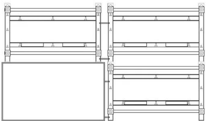
natural_image
Pure architectural or mechanical diagram showing two vertical panels with horizontal supports and a rectangular panel below, no text or symbols present.flowchart
graph LR
    A["Initial Assembly"] --> B["Intermediate Processing"]
    B --> C["Final Grid State"]
Advertencia
natural_image
Pure grid layout with four empty cells and a vertical scale bar on the right (no text or symbols)natural_image
Technical diagram of a mechanical assembly with labeled components and directional arrows (no text or symbols)natural_image
Technical line drawing of a mechanical device with internal components and directional arrows (no text or symbols)natural_image
Pure technical diagram of a mechanical assembly with two vertical arrows indicating upward motion, no text or symbols present.natural_image
Technical diagram of a mechanical assembly with directional arrows indicating movement (no text or labels)
natural_image
Technical diagram of a mechanical assembly with directional arrows indicating movement or force (no text or symbols present)flowchart
graph TD
    A["Assembly"] --> B["Reassembly"]
    B --> C["Assembly with a zoomed-in component"]
    C --> D["Final Assembly with a zoomed-in detail"]
    D --> E["Final Output"]
Advertencia
natural_image
Technical line drawing of a mechanical assembly with no visible text or symbolstext_image
Technical diagram showing assembly steps of a mechanical component with directional arrows indicating process flow.Precaución
flowchart
graph LR
    A["Initial block"] --> B["Arrow pointing right"]
    B --> C["Step 1: Initial block is being folded"]
    C --> D["Step 2: Initial block is being assembled"]
    D --> E["Step 3: Final assembly with internal components"]
    E --> F["Final detail: Fijación del"]
flowchart
graph LR
    A["Grid with left and center cell"] --> B["Grid with right arrow and left side, right side with right arrow"]
flowchart
graph LR
    A["Step 1: Left Side"] --> B["Step 2: U-shaped Arrow"]
    B --> C["Step 3: Right Side"]
    C --> D["Side View: Left Side with Arrow"]
    D --> E["Side View: Right Side with Arrow"]
natural_image
Architectural floor plan diagram showing room layout and structural elements (no text or labels)natural_image
Technical line drawing of a mechanical frame structure with mounting holes and supports (no text or symbols)Planos
text_image
Illustration showing two scenes: a woman holding a book and another person wearing a Samsung T-shirt with 'AS' logo.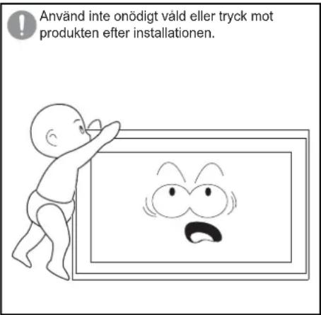
natural_image
Technical line drawing of a metal ladder structure with mounting feet (no text or symbols)natural_image
Technical line drawing of a mechanical frame structure (no text or symbols)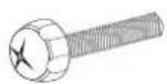
Skruv ⓐ
(M8 X 60mm) : x4
Skruv ⓑ
(M8 X 30mm) : x4
Koppling : x2 Skruvhållare: x4

Träskruv
(M5 X 50mm) : x8

Säkerhetsfäste: x2

Skruv ©
(M5 X 10mm) : x2
text_image
Technical diagram of a structural frame with numbered components and support symbolstext_image
Technical diagram showing labeled structural components with numbered annotations and directional arrows indicating movement or flow.natural_image
Technical line drawing of a mechanical assembly with dimension arrows and cross-sectional view (no text or symbols)natural_image
Pure structural diagram of two vertical beams with mounting holes and directional arrows, no text or symbols presentnatural_image
Technical line drawing of a multi-level structural framework with mounting brackets and supports (no text or symbols)
flowchart
graph TD
    A["Step 1"] --> B["Step 2"]
    B --> C["Step 3"]
text_image
③ ①▲ Varning
natural_image
Pure architectural or structural diagram of a multi-level building frame with horizontal beams and corner supports (no text or symbols)natural_image
Technical line drawing of a mechanical assembly before and after modification, showing structural components and a bolted component (no text or symbols)▲ Varning
natural_image
Technical line drawing of a mechanical assembly with rollers and components (no text or symbols)
natural_image
Technical line drawing of a mechanical assembly with no visible text or symbols
natural_image
Pure architectural or engineering line drawing of structural beams and supports without any text, numbers, or symbolsflowchart
graph LR
    A["Initial Assembly"] --> B["Intermediate Processing"]
    B --> C["Final Grid State"]
▲ Varning
natural_image
Pure grid layout with four empty cells and a vertical scale bar on the right (no text or symbols)natural_image
Technical line drawing of a mechanical assembly with no visible text or symbolsnatural_image
Technical line drawing of a mechanical device with internal components and directional arrows (no text or symbols)natural_image
Pure technical diagram of a mechanical assembly with two vertical arrows indicating upward motion, no text or symbols present.natural_image
Technical diagram of a mechanical assembly with directional arrows indicating movement (no text or labels)
natural_image
Pure mechanical assembly diagram showing a lever mechanism with no text or symbolsnatural_image
Technical line drawing showing structural components before and after assembly (no text or symbols)▲ Varning
natural_image
Technical line drawing of a mechanical assembly with no visible text or symbolsDemontera skärmarna
text_image
Technical diagram showing assembly steps of a mechanical component with labeled parts and directional arrows indicating process flow.⚠ Försiktighet
flowchart
graph LR
    A["Initial Setup"] --> B["Assembly"]
    B --> C["Adjustment"]
    C --> D["Final Assembly with Fixera skärmen in hållaren"]
natural_image
Pure diagram of a mechanical or electrical component with no text, numbers, or symbols
natural_image
Pure mechanical assembly diagram showing four rectangular blocks with internal components and directional arrows, no text or symbols present.natural_image
Pure architectural floor plan lines without any text, numbers, or symbols
natural_image
Technical line drawing of a mechanical frame structure with mounting holes and supports (no text or symbols)Ritningar
text_image
Illustration showing two scenes: a woman holding a book and another person wearing a Samsung T-shirt with 'AS' logo.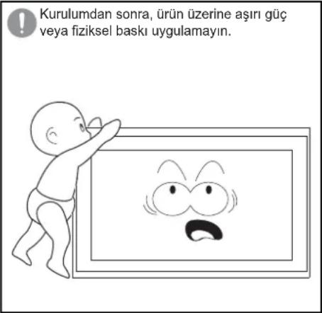
natural_image
Technical line drawing of a metal frame structure with mounting holes (no text or symbols)
Vida ©
(M5 X 10mm) : x2
text_image
Technical diagram of a structural frame with numbered components and support symbolstext_image
Technical diagram showing labeled structural components with numbered annotations and directional arrows indicating movement or flow.natural_image
Technical line drawing of a mechanical assembly with dimension arrows and cross-section detail (no text or symbols)natural_image
Pure structural diagram of two vertical beams with mounting holes and directional arrows, no text or symbols presentnatural_image
Technical line drawing of a multi-level structural frame with mounting holes and supports (no text or symbols)
flowchart
graph TD
    A["Step 1"] --> B["Step 2"]
    B --> C["Step 3"]

text_image
③ ①⚠ Uyari
natural_image
Pure architectural or structural line drawing of a multi-level building frame with no text, numbers, or symbolsnatural_image
Technical line drawing of a mechanical assembly before and after modification, showing structural components and mounting features (no text or symbols)▲ Uyari
natural_image
Technical line drawing of a mechanical assembly with rollers and components (no text or symbols)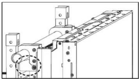
natural_image
Technical line drawing of a mechanical assembly with no visible text or symbols
natural_image
Pure architectural or engineering line drawing of structural beams and supports without any text, numbers, or symbolsflowchart
graph LR
    A["Initial Assembly"] --> B["Intermediate Processing"]
    B --> C["Final Grid State"]
▲ Uyari
natural_image
Pure grid layout with four empty cells and a vertical scale bar on the right (no text or symbols)natural_image
Technical line drawing of a mechanical assembly with no visible text or symbolsnatural_image
Technical line drawing of a mechanical device with internal components and directional arrows (no text or symbols)natural_image
Pure technical diagram of a mechanical assembly with two vertical arrows indicating upward motion, no text or symbols present.natural_image
Technical diagram of a mechanical assembly with directional arrows indicating movement (no text or symbols)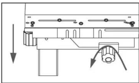
natural_image
Technical diagram of a mechanical assembly with directional arrows indicating movement or force (no text or symbols present)natural_image
Technical line drawing of a mechanical assembly with no visible text or symbolstext_image
Technical diagram showing assembly steps of a mechanical component with labeled parts and directional arrows indicating process flow.⚠️ Dikkat
flowchart
graph LR
    A["Grid with left and center cell"] --> B["Grid with right arrow and left arrow, right arrow"]
flowchart
graph LR
    A["Step 1: Left Side"] --> B["Step 2: U-shaped Arrow"]
    B --> C["Step 3: Right Side"]
    C --> D["Side View: Left Side with Arrow"]
    D --> E["Side View: Right Side with Arrow"]
natural_image
Architectural diagram showing a structural layout with a central column and an arrow indicating upward movement, alongside a detailed 3D model of a tower structure (no text or symbols)natural_image
Technical line drawing of a mechanical frame structure with mounting holes and supports (no text or symbols)Çizimler
natural_image
Illustration of two people: one holding a notebook and the other talking on a phone with an 'AS' cap (no text or symbols in the image)natural_image
Cartoon illustration of a baby pointing at a framed picture with an angry face (no text or symbols)natural_image
Technical line drawing of a metal ladder or support frame with mounting holes (no text or symbols)
natural_image
Pure mechanical frame diagram without any text, numbers, or symbolstext_image
Technical diagram of a structural frame with numbered components and support symbols※ ネジの締め方
3X50 ドリルで穴を開けます。

text_image
Technical diagram showing four labeled structural components (1, 2, 3, 4) with directional arrows indicating movement or flow.警告
natural_image
Technical diagram showing a mechanical assembly with arrows indicating direction, including a detailed close-up of the internal components (no text or symbols present)natural_image
Pure structural diagram of two vertical beams with mounting holes and directional arrows, no text or symbols presentnatural_image
Technical line drawing of a structural frame with supports and mounting holes (no text or symbols)
flowchart
graph TD
    A["Step 1"] --> B["Step 2"]
    B --> C["Step 3"]

text_image
③ ①警告
natural_image
Pure architectural or structural diagram of a multi-level building frame with horizontal beams and corner supports (no text or symbols)natural_image
Technical line drawing of a mechanical assembly before and after modification, showing structural components and a bolted component (no text or symbols)警告
natural_image
Technical line drawing of a mechanical assembly with rollers and components (no text or symbols)
natural_image
Technical line drawing of a mechanical assembly with no visible text or symbols
natural_image
Pure architectural or engineering line drawing of structural beams and supports without any text, numbers, or symbolsflowchart
graph LR
    A["Initial Assembly"] --> B["Intermediate Processing"]
    B --> C["Final Grid State"]
警告
natural_image
Pure grid layout with four equal sections and a vertical scale bar on the right (no text or symbols)natural_image
Technical line drawing of a mechanical assembly with no visible text or symbolsモニターを後ろに動かす
natural_image
Technical line drawing of a mechanical assembly with no visible text or symbolsnatural_image
Pure technical diagram of a mechanical assembly with two vertical arrows indicating upward motion, no text or symbols present.モニターを下げるモニターを上げる

natural_image
Technical diagram of a mechanical assembly with directional arrows indicating movement (no text or labels)
natural_image
Pure mechanical assembly diagram without any text, numbers, or symbolsnatural_image
Technical line drawing of a mechanical assembly with no visible text or symbolsモニターの取り外し
- 上段モニターの取り外し ジ
オウオ
text_image
Technical diagram showing assembly steps of a mechanical component with labeled parts and directional arrows indicating process flow.注意
natural_image
Pure diagram of a 3x3 grid with a central rectangular block and an arrow, no text or symbols present.
natural_image
Pure mechanical assembly diagram showing four rectangular blocks with directional arrows indicating movement (no text or symbols)natural_image
Technical line drawing of a mechanical frame structure with mounting holes and supports (no text or symbols)natural_image
Technical line drawing of a metal frame structure with mounting holes (no text or symbols)显示器安装支架 a 壁挂支架 b
natural_image
Pure mechanical frame diagram without any text, numbers, or symbols

连接杆:x2 螺钉固定器:x4
螺钉 ^① (M8 X 60mm) : x4
螺钉 ⑥
(M8 X 30mm) : x4
natural_image
Technical line drawing of a server rack unit with ventilation grilles and drive bays (no text or symbols)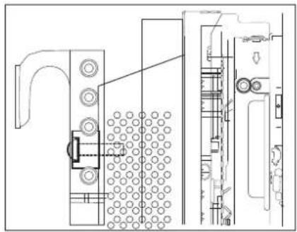
natural_image
Technical line drawing of a mechanical assembly with no visible text or symbols警告
检查确认支架 ⓐ 是否固定到显示器。
将支架 ⑥ 安装到墙壁
- 用木螺钉将支架 ⑥ 牢固地固定到墙壁。
text_image
Technical diagram of a structural frame with numbered components and support symbols※ 螺钉固定方法
使用 3X50 钻在墙壁上钻一个孔。
清除所钻孔内的杂物。

将木螺钉固定到孔中。
text_image
Technical diagram showing four labeled structural components (1, 2, 3, 4) with directional arrows indicating movement or flow.警告
natural_image
Technical line drawing of a mechanical assembly with dimension arrows and cross-section detail (no text or symbols)natural_image
Pure structural diagram of two vertical beams with mounting holes and directional arrows, no text or symbols presentnatural_image
Technical line drawing of a structural frame with supports and mounting holes (no text or symbols)
flowchart
graph TD
    A["Step 1"] --> B["Step 2"]
    B --> C["Step 3"]
    C --> D["End"]
    style A fill:#f9f,stroke:#333
    style B fill:#ccf,stroke:#333
    style C fill:#cfc,stroke:#333
    style D fill:#fcc,stroke:#333

text_image
③ ①警告
natural_image
Pure architectural or structural line drawing of a multi-level building frame with no text, numbers, or symbols按照上述步骤增加支架的数量。
排列显示器
natural_image
Technical diagram showing a mechanical assembly before and after modification, with no visible text or symbols.警告
flowchart
graph LR
    A["Rectangular Units with 2x4 side labels"] --> B["Split into two rectangles"]
    B --> C["Empty rectangular unit with four empty sections"]
警告
在安装时请小心不要夹到手指。
微调
natural_image
Pure grid layout with four equal sections and a vertical scale bar on the right (no text or symbols)natural_image
Technical diagram of a mechanical assembly with labeled components and directional arrows (no text or symbols)向后移动显示器
natural_image
Technical line drawing of a mechanical assembly with no visible text or symbols- 调整上下显示器之间的高度差。
natural_image
Pure technical diagram of a mechanical assembly with two vertical arrows indicating upward motion, no text or symbols present.降低显示器提升显示器

natural_image
Technical diagram of a mechanical assembly with directional arrows indicating movement (no text or labels)
natural_image
Pure mechanical assembly diagram showing a lever mechanism with no text or symbols☆ 要调整上层显示器之间的高度差:
natural_image
Technical line drawing of a mechanical assembly with no visible text or symbols拆下显示器
1. 拆下上面的显示器
natural_image
Technical diagram showing a mechanical assembly before and after assembly, with no visible text or symbols.注意
flowchart
graph TD
    A["Grid with left and right sides"] --> B["Grid with left arrow, right arrow"]
flowchart
graph LR
    A["Top: Column with U-shaped arrow"] --> B["Left: Column with horizontal bars"]
    B --> C["Right: Column with horizontal bars and directional arrows"]
natural_image
Architectural floor plan diagram showing room layout and structural elements (no text or labels)- 提起中间的显示器将它从屏幕墙中拆下。
产品规格
| 尺寸(mm) W955 X H590.5 X D93 | |
| 重量(kg) 7 | |
| VESA 标准壁挂支架(mm) | 600 X 400 |
注意
natural_image
Technical line drawing of a mechanical frame structure with mounting holes and supports (no text or symbols)图纸
1. 显示器安装支架 ①
- 壁挂支架 ⑥
目錄
安全意事項 01 安全意事項 注 注
介紹 02 拆開包裝
02 將托架
a 連接到顯示器
03 將托架
b 掛載到牆上
06 排列顯示器
07 微調
10 拆卸顯示器
產品規格 11 產品規格
產品圖 12 產品圖
13 圖
安全意事項注
natural_image
Technical line drawing of a metal ladder or support frame with mounting holes (no text or symbols)顯示器掛載托架 ① 掛牆托架 ②
natural_image
Technical line drawing of a mechanical frame or structural component with no visible text or symbols

聯結器:x2 螺絲固定座:x4

螺絲 @
(M8 X 60mm) : x4

螺絲 ⑥
(M8 X 30mm) : x4
木質螺絲
(M5 X 50mm) : x8
安全緊固: x2

螺絲 ©
(M5 X 10mm) : x2
將托架 @ 連接到顯示器
natural_image
Technical line drawing of a server rack unit with ventilation ducts and drive bays (no text or symbols)
natural_image
Technical line drawing of a mechanical assembly with no visible text or symbols
警告
檢查並確認托架 ⓐ 已固定顯示器。
將托架 ⑥ 掛載到牆上
於
- 使用木質螺絲將托架 ⑥ 緊密固定牆上。
text_image
Technical diagram of a mechanical or structural assembly with numbered components and support symbols※ 如何擰緊螺絲
使用 3X50 電鑽鑽孔。
清理鑽孔內部。
將木質螺絲鎖人孔中。
natural_image
Technical line drawing of a mechanical assembly with an inset close-up showing a detailed view of the component (no text or symbols present)於
natural_image
Pure structural diagram of two vertical frames connected by horizontal beams, with no text, numbers, or symbols present.natural_image
Technical line drawing of a structural frame assembly with supports and mounting holes (no text or symbols)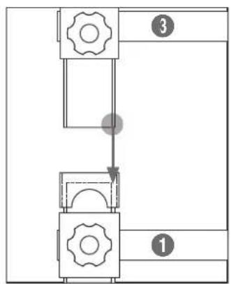
flowchart
graph TD
    A["Step 1"] --> B["Step 2"]
    B --> C["Step 3"]

text_image
③ ①警告
natural_image
Pure architectural or structural diagram of a multi-level building frame with horizontal beams and corner supports (no text or symbols)② 按照以上步驟增加托架數量。
排列顯示器
natural_image
Technical line drawing of a mechanical assembly before and after modification, showing structural components and mounting features (no text or symbols)


natural_image
Technical line drawing of a mechanical assembly with rollers and components (no text or symbols)
natural_image
Technical line drawing of a mechanical assembly with no visible text or symbols
natural_image
Pure architectural or engineering line drawing of structural beams and supports without any text, numbers, or symbolsflowchart
graph LR
    A["Initial Assembly"] --> B["Intermediate Processing"]
    B --> C["Final Grid State"]


請小心勿在安裝期間夾住手指。
微調
natural_image
Pure grid layout with four equal sections and a vertical scale bar on the right (no text or symbols)果
natural_image
Technical line drawing of a mechanical assembly with no visible text or symbols將顯示器後移
natural_image
Technical diagram of a mechanical assembly with no visible text or symbols- 修正上下顯示器之間的高度差距。
natural_image
Pure technical diagram of a mechanical assembly with two vertical arrows indicating upward motion, no text or symbols present.降下顯示器升起顯示器
natural_image
Technical diagram of a mechanical assembly with directional arrows indicating movement (no text or symbols)
natural_image
Technical diagram of a mechanical assembly with directional arrows indicating movement or force (no text or symbols present)
☆ 若要調整上層顯示器的高度差距,
natural_image
Technical line drawing of a mechanical assembly with no visible text or symbols拆卸顯示器
1. 拆卸上層顯示器
text_image
Technical diagram showing assembly steps of a mechanical component with directional arrows indicating process flow.flowchart
graph LR
    A["Grid with left and center cell"] --> B["Grid with right arrow and left arrow"]
    B --> C["Grid with right arrow and center cell"]
flowchart
graph LR
    A["Start State"] --> B{Transformation}
    B --> C["Left State with Arrow indicating clockwise motion"]
    B --> D["Right State with Arrow indicating forward motion"]
natural_image
Architectural floor plan diagram showing room layout and structural elements (no text or labels)- 抬起中層顯示器,從視訊牆拆下。
產品規格
natural_image
Technical line drawing of a mechanical frame structure with mounting flanges and bolted joints (no text or symbols)圖
1. 顯示器掛載托架 ⓐ
text_image
600 50 45 11.5 10.5 67 45 400 515 M8 X L60 26 62.22. 掛牆托架 ⑥

text_image
900 650 52 45 57 26.7 10 8 57 590.5 26 71 10 8 330 480 160 33 217 M8 X L60목차
natural_image
Technical line drawing of a metal frame structure with mounting holes (no text or symbols)natural_image
Technical line drawing of a server rack unit with ventilation ducts and drive bays (no text or symbols)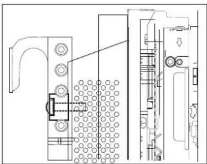
natural_image
Technical line drawing of a mechanical assembly with no visible text or symbols
경고
text_image
Technical diagram of a structural frame with numbered components and lighting indicators※ 나사 고정 방법
3X50의 드릴로 구멍을 뜨으세요.
ロック은 구멍을 청소하세요.

natural_image
Technical line drawing of a mechanical assembly with dimension arrows and a close-up view of the internal components (no text or symbols)natural_image
Pure structural diagram of two vertical beams with mounting holes and directional arrows, no text or symbols presentnatural_image
Technical line drawing of a structural frame with supports and mounting holes (no text or symbols)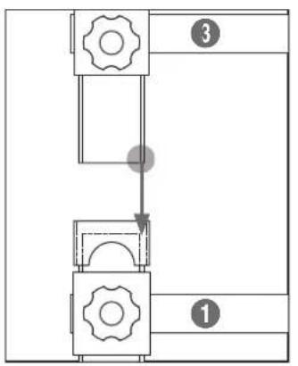
flowchart
graph TD
    A["Step 1"] --> B["Step 2"]
    B --> C["Step 3"]
text_image
③ ①
경고
그림과 같이 ③번 브라켓의
아랫 부분이 ①번 브라켓의 웃
부분에 정확히 안착되어 맞당도록
조립하세요.
natural_image
Pure architectural or structural line drawing of a multi-level building frame with no text, numbers, or symbolsnatural_image
Technical line drawing of a mechanical assembly before and after modification, showing structural components and mounting features (no text or symbols)
경고
natural_image
Technical line drawing of a mechanical assembly with rollers and components (no text or symbols)
natural_image
Technical line drawing of a mechanical assembly with no visible text or symbols
natural_image
Pure architectural or engineering line drawing of structural beams and supports without any text, numbers, or symbolsflowchart
graph LR
    A["Initial Assembly"] --> B["Intermediate Processing"]
    B --> C["Final Grid State"]

경고
natural_image
Pure grid layout with four equal quadrants and a vertical line on the right (no text or symbols)
natural_image
Technical line drawing of a mechanical assembly with no visible text or symbols모니터를 뒤로 이동시킬 때

natural_image
Technical line drawing of a mechanical device with no visible text or symbols2.상,하 단차조절
natural_image
Pure technical diagram of a mechanical assembly with two vertical arrows indicating upward motion, no text or symbols present.natural_image
Technical diagram of a mechanical assembly with directional arrows indicating movement (no text or symbols)
natural_image
Technical diagram of a mechanical assembly with directional arrows indicating movement or force (no text or symbols present)
natural_image
Technical line drawing showing structural assembly before and after modification (no text or symbols)▲경고
natural_image
Technical line drawing of a mechanical assembly with no visible text or symbols모니터 분해방법
1. 상단 모니터 분해방법
text_image
Technical diagram showing assembly steps of a mechanical component with labeled parts and directional arrows indicating process flow.⚠ 주의
flowchart
graph LR
    A["Grid with left arrow"] --> B["Rectangular Layout with right arrow"]
flowchart
graph LR
    A["Top Section"] --> B["Left Section"]
    B --> C["Right Section"]
    style A fill:#f9f,stroke:#333
    style C fill:#bbf,stroke:#333
    subgraph Left_Chase
        D["Top Section"] --> E["Left Section"]
        E --> F["Right Section"]
    end
    subgraph Right_Chase
        G["Top Section"] --> H["Left Section"]
        H --> I["Right Section"]
    end
natural_image
Architectural diagram showing a structural layout with a crane lifting a beam, alongside a detailed cross-section of the tower (no text or labels)- 모니터를 들어 올려서 분해하세요.
제품 규격
natural_image
Technical line drawing of a mechanical frame structure with mounting holes and supports (no text or symbols)도면
1. 모니터 고정용 브라켓®

text_image
600 50 45 11.5 10.5 67 45 400 515 M8 X L60 26 62.22. 벽 고정용 브라켓⑥

text_image
900 650 52 45 57 26.7 10 8 590.5 26 71 10 8 330 480 160 33 217 M8 X L60SAMSUNG