
PDK-TS36B - Audio System PIONEER - Free user manual and instructions
Find the device manual for free PDK-TS36B PIONEER in PDF.
| Product Type | TV stand base |
| Brand | PIONEER |
| Model | PDK-TS36B |
| Dimensions (W × H × D) | 577 × 321 × 380 mm (with S support columns) |
| Weight | 10.8 kg |
| Compatibility | PDP-5020FD, PDP-111FD, PDP-LX5090H, PDP-LX5090, PDP-LX509A, PDP-C509A |
| Swivel angle | 10° left and right |
| Tilt angle | Approximately 2° forward and backward |
| Main material | Steel |
| Package contents | TV stand base, support columns (L and S), fixing screws (M8×16, M8×30, M8×40), cable ties, hex keys, instruction manual |
| Installation | Requires two people, flat and stable surface |
| Safety precautions | Use fixing screws (M8) and cables to prevent tipping over |
| Cleaning | Wipe with a soft dry cloth |
| Intended use | Indoors, on a TV cabinet |
| Cable management | Cable ties included |
| Anti-rotation fixing | M4 screws to fix rotation at the front |
| Number of screws included | 8 screws (4 M8×16, 2 M8×30, 2 M8×40) |
| Color | Black (estimated) |
| Recommended cabinet depth | 420 mm or more |
| Base width | 577 mm |
| Base height | 321 mm |
| Base depth | 380 mm |
Frequently Asked Questions - PDK-TS36B PIONEER
User questions about PDK-TS36B PIONEER
0 question about this device. Answer the ones you know or ask your own.
Ask a new question about this device
Download the instructions for your Audio System in PDF format for free! Find your manual PDK-TS36B - PIONEER and take your electronic device back in hand. On this page are published all the documents necessary for the use of your device. PDK-TS36B by PIONEER.
USER MANUAL PDK-TS36B PIONEER
OPERATING INSTRUCTIONS
MODE D'EMPLOI
BEDIENUNGSANLEITUNG
ISTRUZIONI PER L'USO
HANDLEIDING
Thank you for buying Pioneer's product.
Please read through the Operating Instructions to learn how to operate your model safely and properly.
Please be advised to keep the Operating Instructions in your place for future reference.
Installation
- Consult your dealer if you encounter any difficulties with this installation.
- Pioneer is not liable for any damage resulting from improper installation, improper use, modification, or natural disasters.
IMPORTANT NOTICE
Record the model number and serial number of this equipment below.
Model No. Serial No.
Keep these numbers for future use.
Contents
Cautions ...... 2
Checking the Enclosed Parts....3
Assembling the Stand 4
Attaching the Pioneer Television .... 5
Forward/Backward Angle of Inclination
Adjustment Mechanism 6
Installing the Product on a TV table etc. 7
Preparing the Cables 8
Preventing Equipment from Falling Over 9
Fixing the rotation to the front.... 10
Detaching the Pioneer Television from
the Stand 10
Specifications 10
Dimensions Diagram 11

CAUTION
This symbol refers to a hazard or unsafe practice which can result in personal injury or property damage.
Cautions

This product is a table top stand exclusively designed for Pioneer televisions (PDP-5020FD / PDP-111FD / PDP-LX5090H / PDP-LX5090 / PDP-LX509A / PDP-C509A).
Use with other model is capable of resulting in instability causing possible injury. For further information, please contact the store where you purchased your display.
Do not install or modify the product other than specified. Do not use this stand for a Pioneer television other than those designated and do not modify it or use it for other purposes.
Improper installation is extremely dangerous because it may result in it falling over or other accident.
Installation Location
- Select a location that is strong enough to support the weight of the stand and the displays.
- Make sure to place it in a level and stable location.
- Do not install it outdoors or in a wet place such as at a hot spring or near a beach.
- Do not install the stand where it may be subjected to vibration or shock.
Assembling and Installation
- Assemble the stand in accordance with the assembly instructions and securely attach all screws at the designated locations.
There have been cases where unforeseen accidents such as the equipment breaking or falling over occurred after the installation of the display because the stand was not installed as instructed. - The display must always be installed by two or more people to assure it is installed safely.
- Before installation, turn off the power for the display and peripheral devices then remove the power cord plug from the power outlet.
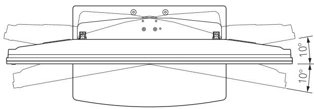
This product rotates 10^ to the left and right and inclines approximately 2^ forward and backward.
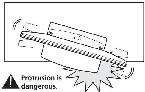
Do not place objects within the range of rotation of this product and the Pioneer television. Install this product so that during routine use or when it is rotated, it does not protrude from the TV table or other location it has been installed. Failure to do so could cause unforeseen accidents such as the equipment breaking or falling over (see page 7). While adjusting its angle forward and backward, be extremely careful to keep your hands out of the space between the bottom of the Pioneer television and the stand (see page 6).
Prevent accidents caused by the product falling over, by taking reliable measures to prevent it from falling over (see page 9).
Checking the Enclosed Parts
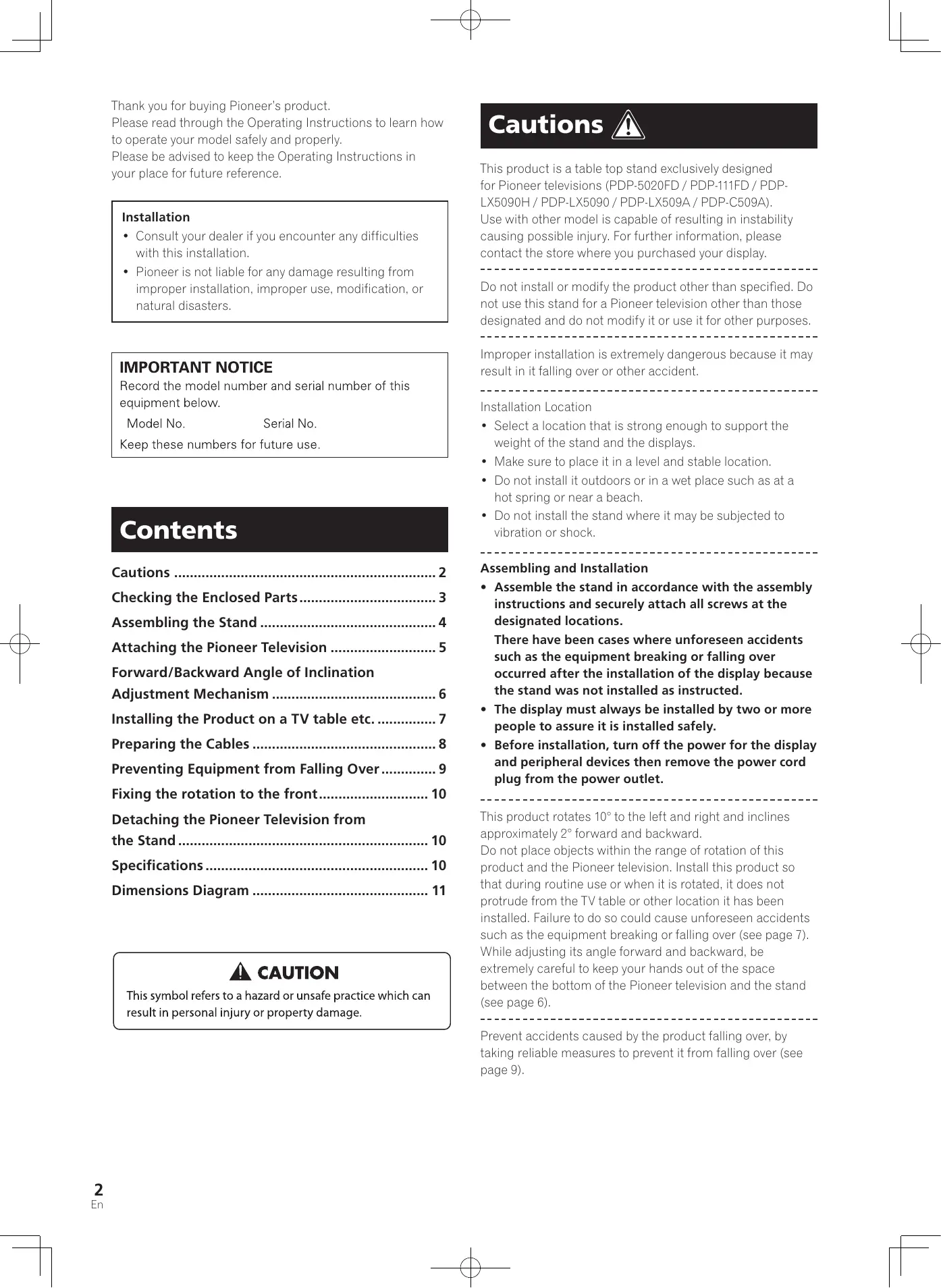
Check to make sure that you have all the enclosed parts before assembly and installation.
- Table top stand x 1
natural_image
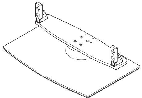
Technical line drawing of a mechanical support bracket with mounting holes and a curved component (no text or symbols)- Support columns L x 2 [long columns]
* For under speaker models
natural_image
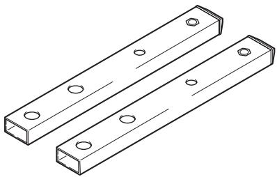
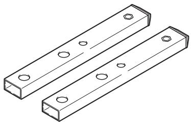
Technical line drawing of two rectangular metal beams with holes, no text or symbols present- Support columns S x 2 [short columns]
* For except under speaker models
natural_image
Technical line drawing of two rectangular metal plates with holes, no text or symbols present- Installation screws ① (M8 x 16 mm: silver) x 4 [used to anchor the support columns and the table top stand]
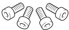
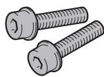
• Installation screws ② (M8 x 30 mm: silver) x 2
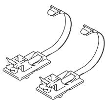
- Cable binders x 2
natural_image
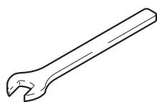
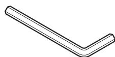
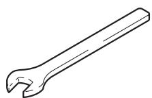
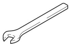
Pure electrical circuit lines without any symbols- C wrench x 1 (10 mm)
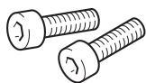
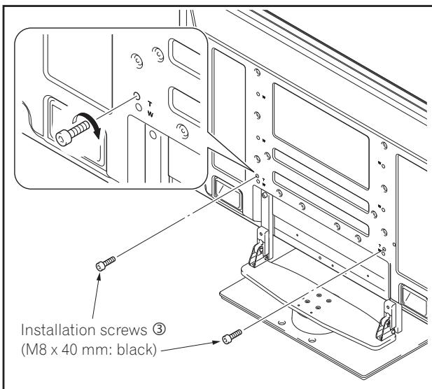
• Installation screws ③ (M8 x 40 mm: black) x 2
- Hexagonal wrench x 1 (Diagonal size: 6 mm)
- Operating instructions (this document) x 1
Assembling the Stand
Note
• Always assemble it on a flat table etc.
- Insert the screws in the holes vertically and do not tighten them with more force than necessary.
Assembly Procedure
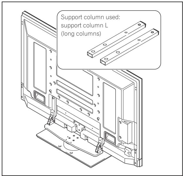
1 Select the support columns to attach.
Select the support columns according to the Pioneer television that you have purchased (Only one type of the two types of available support columns should be used).
When the Pioneer television you have purchased is under speaker models.
[Support column used: support column L (long columns)]
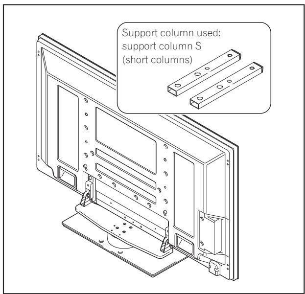
When the Pioneer television you have purchased is except under speaker models.
[Support column used: support column S (short columns)]
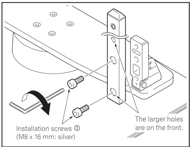
2 Secure the support column to the stand with the Installation screws ① (4 locations on the left and right).
Using the enclosed hexagonal wrench, first loosely attach the top attachment screw, then loosely attach the bottom attachment screw.
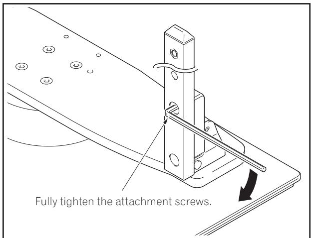
3 Fully tighten the Installation screws (4 locations on the left and right).
Note
Be sure to carefully store the unused support columns, the hexagonal wrench, the C wrench, and the Operating Instructions together.
Attaching the Pioneer Television

Caution
The weight of a 50 inch Pioneer television (without speaker) is about 34 kg (75 lbs), they have no depth, and are unstable. Therefore, at least two people must assemble and install them.
Note
- Be sure to install it on a flat stable location.
- Insert the screws in the holes vertically and do not tighten them with more force than necessary.
- Make sure that you install the support columns reliably with reference to the procedure in "Assembling the Stand".
Attachment Method
1 Attaching the Pioneer television to the stand.
Fit the stand's support columns to the bottom of the Pioneer television as indicated by the arrows, then slowly insert them vertically. Be extremely careful not to insert the support columns of the stand into any part of the Pioneer television other than the stand insertion slots. Note that doing so might damage the Pioneer television panel or its ports or result in the warping of the stand.
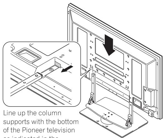
Line up the column supports with the bottom of the Pioneer television as indicated in the accompanying diagram.
2 Securing the Pioneer television with Installation screws ②.
Secure them using the enclosed hexagonal wrench.
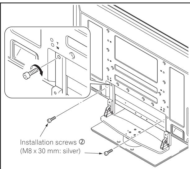
3 Securing the Pioneer television with Installation screws ③.
Attach the Pioneer television at the points marked with "T" using the enclosed hexagonal wrench.

Caution
There have been cases where unforeseen accidents such as the equipment breaking or falling over occurred because the stand was installed with wrong screws.
4 Attaching the speakers.
Refer to the operating instructions for the speaker for the installation method.
Forward/Backward Angle of Inclination Adjustment Mechanism
On this stand, you can adjust the angle of inclination of the Pioneer television within a range of approximately 2^ forward or backward according to your preference.
Note
- Be sure to adjust the angle only after you have attached the Pioneer television.
- Be sure to install it on a flat table or other flat surface.
- Be sure to hold the top of the Pioneer television with your hand while adjusting the angle.
Adjustment Procedure
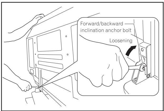
1 Loosen the forward/backward inclination anchor bolts using the enclosed C wrench (2 locations on the left and right).
While being sure to hold the top of the Pioneer television with your hand, loosen the forward/backward inclination anchor bolts on the left and right sides by rotating them upwards using the enclosed C wrench.
2 Set the angle you prefer.
Set the angle you prefer by slowly moving the Pioneer television.
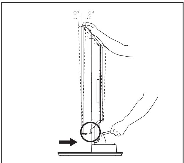
Note
While adjusting the angle, be very careful to keep your hands out of the place indicated by the arrow on the figure.
3 Tighten the forward/backward inclination anchor bolts (2 locations on the left and right).
Firmly tighten the forward/backward inclination anchor bolts on the left and right sides by rotating them downward using the enclosed C wrench. Be sure to hold the top of the Pioneer television with your hand until you have fully tightened the bolts.
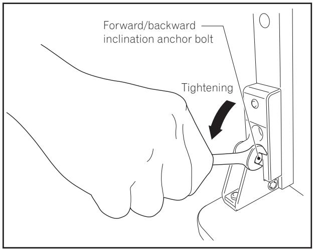
4 Check once more to make sure that the forward/backward inclination anchor bolts are fully tightened.
Installing the Product on a TV table etc.
Be sure to observe the following precautions when moving or installing this product with a Pioneer television into a TV table or other enclosure.
Precautions when moving

- When moving the product more than a few meters, first remove the speaker, then remove the Pioneer television from the stand and move the speaker, Pioneer television, and stand separately.
- When detaching the Pioneer television from the stand, be sure to follow the procedure described in "Detaching the Pioneer Television from the Stand" on page 10.
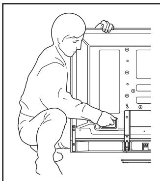
Precautions when installing in a TV table or other enclosure

When installing in a TV table or other enclosure, hold the Pioneer television by the handles located on the rear of the Pioneer television. If you hold the speakers, they may be damaged or twisted.
When the Pioneer television you have purchased is under speaker models.
Hold the Pioneer television by its handles and from the top.
natural_image
Line drawing of a person installing or adjusting a device panel (no text or symbols present)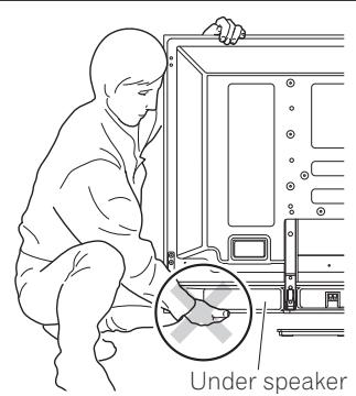
natural_image
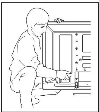
Illustration of a person installing or adjusting an electronic device with a magnified inset showing a warning symbol (no text or labels)When the Pioneer television you have purchased is except under speaker models.
Hold the Pioneer television by its handles and from the top.
natural_image
Line drawing of a person in protective suit working on a device panel (no text or symbols)Installation precautions
Make sure that you always secure a space at least as large as that shown in the following diagram in front of and behind the table top stand.
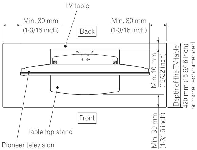

- If the stand protrudes from the TV table, it could cause unforeseen accidents such as the equipment breaking or falling over.
- When rotating, take care not to allow the display to bump into walls or surrounding objects.
◆ Range of angle rotation
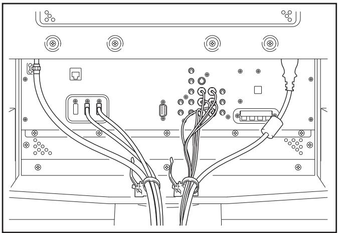
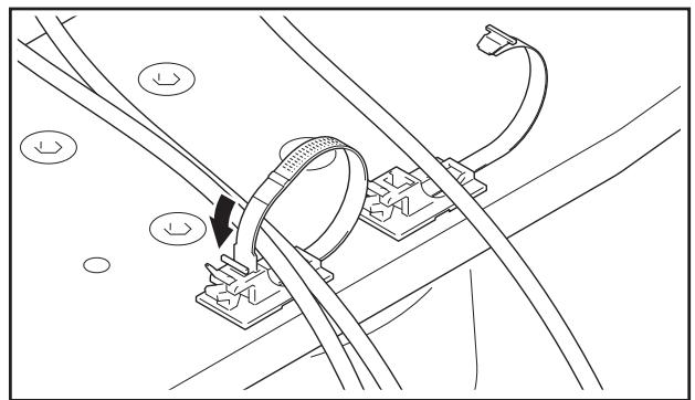
Preparing the Cables
Use the enclosed cable binders to bind the cables.
Note
Be very careful not to apply force to the bases of the cables.
natural_image
Line drawing of a server rack with connected cables and connectors (no text or symbols)Using the cable binders
1 Insert the cable binder through the hole on the top of the rotating platform of the stand.
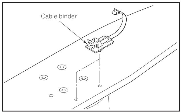
2 Gathering cables and placing them on the cable binder.

natural_image
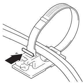
Technical line drawing of railway tracks with overhead cable and support structures (no text or symbols)3 Locking the cable binder.
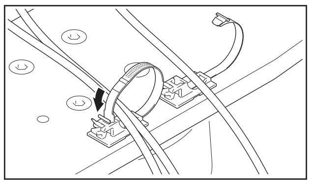
natural_image
Technical line drawing of a mechanical assembly with no visible text or symbols◆ Removing a cable binder
The lock is released by pushing the part indicated by the arrow in the figure.

natural_image
Technical line drawing of a mechanical clamp or bracket assembly (no text or symbols)Preventing Equipment from Falling Over
After installing the stand, be sure to take special care to ensure that the Pioneer television will not fall over.
- Because of the Pioneer television's weight, if it could fall down, this can result in injury.
- For safety, be sure to take special care to ensure that the Pioneer television will not fall over.
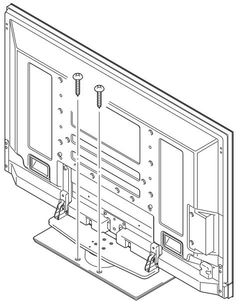
Stabilizing on TV table or other location
Stabilize the equipment as shown in the diagram using screws that are available on the market.
Note
- A TV table with adequate strength, width and depth should always be used to support the Pioneer television. Failure to do so could result in falling over.
- To stabilize the Pioneer television on a TV table, use screws that have a nominal diameter of 6 mm (1/4 inch). Select the appropriate screws after consulting a professional installer if necessary.
natural_image
Technical line drawing of a computer monitor rear panel with screw holes and mounting brackets (no text or symbols)
Caution
- A table with adequate strength should always be used to support the Pioneer television. Failure to do so could result in personal injury and physical damage.
- When installing the Pioneer television, please take the necessary safety measures to prevent it from falling or overturning in case of emergencies, such as earthquakes, or of accidents.
- If you do not take these precautions, the Pioneer television could fall down and cause injury.
- The screws, hooks and other fittings that you use to secure the Pioneer television to prevent it from overturning will vary according to the composition and thickness of the surface to which it will be attached.
- Select the appropriate screws, hooks and other fittings after first inspecting the surface carefully to determine its thickness and composition and after consulting a professional installer if necessary.
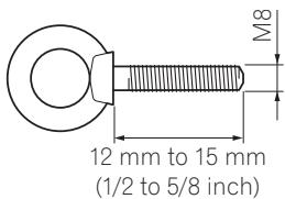
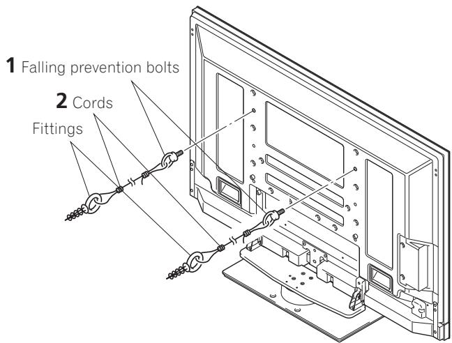
Using a wall for stabilization
1 Attaching falling prevention bolts to the Pioneer television.
2 Using strong cords to stabilize it appropriately and firmly to a wall, pillar, or other sturdy element.
- Perform this work in the same way on the left and right sides.
- The length of the cords used must be long enough to allow the stand to rotate freely.
Note
Use falling prevention bolts, ropes and fittings that are available on the market.
Recommended bolts:
Nominal diameter M8
Length 12 mm to 15 mm (1/2 to 5/8 inch)
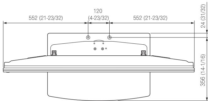
◆ Position of table screws: Without speakers
Unit: mm (inch)
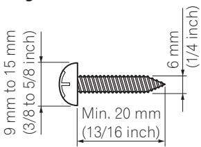
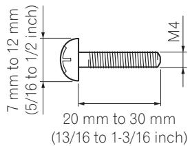
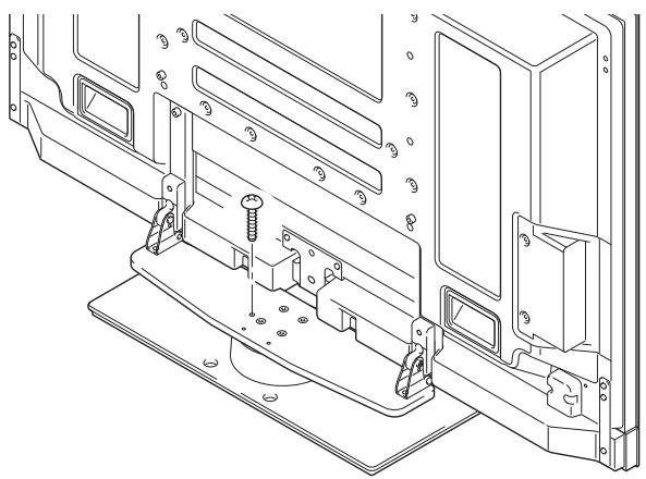
Fixing the rotation to the front
Stabilize the equipment as shown in the diagram using screws that are available on the market.
Note
Use a screw that has a nominal diameter of M4 and length from 20 mm to 30 mm (13/16 to 1-3/16 inch) to fix the rotation to the front.
natural_image
Technical line drawing of a mechanical assembly with mounting brackets and bolts (no text or symbols)Detaching the Pioneer Television from the Stand

Caution
To remove the Pioneer television from the stand, be sure to always follow the procedure described below to prevent accidents.
1 First, confirm that the forward/backward inclination anchor bolt is securely tightened.
2 First clear a space on a flat floor etc. where you can lay the Pioneer television flat, then lay a sheet to protect it from scratches or other damage.
3 Remove the speakers.
4 Referring to steps 2 and 3 in "Attaching the Pioneer Television" (Page 5.), remove the installation screws (4 screws).
Note
Do not remove the screws (M8 x 16 mm: silver) by procedure 2 in Page 5. The support columns might slip out of place and fall over.
5 Holding the Pioneer television by its handles and from the bottom, lift the display vertically.
6 Place the Pioneer television slowly onto the sheet laid out in step 2 with its screen facing downwards.
Note
When reattaching the Pioneer television to the stand, be certain that the left/right support columns are set at the same angle.
Specifications
External dimensions 577 mm (W) x 321 mm (H) x 380 mm (D) (22-23/32 in. (W) x 12-5/8 in.(H) x 14-31/32 in. (D)) [When using the support columns S]
Weight 10.8 kg (23.9 lbs)
- The above specifications and exterior may be modified without prior notice to improve the product.
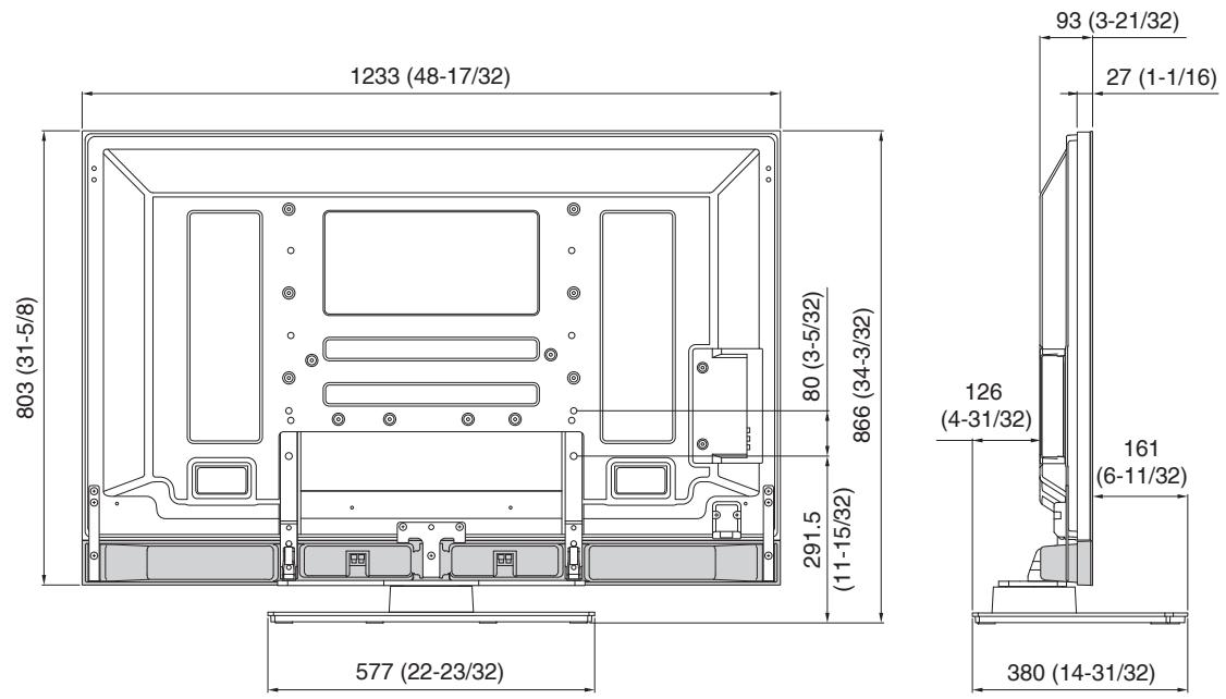
Dimensions Diagram
50 inch display model (under speaker models)
Unit: mm (inch)
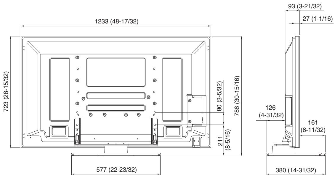
50 inch display model (except under speaker models)
Unit: mm (inch)
natural_image
Technical line drawing of a mechanical component with mounting brackets and a central circular feature (no text or symbols)natural_image
Technical line drawing of two rectangular metal beams with holes, no text or symbols presentnatural_image
Technical line drawing of two rectangular metal bars with holes, no text or symbols presentnatural_image
Pure electrical circuit lines without any symbolsnatural_image
Technical illustration of a computer monitor with an inset showing a close-up of the screen and a black downward arrow indicating a component (no text or symbols present)natural_image
Line drawing of a person installing or adjusting equipment on a cabinet (no text or symbols)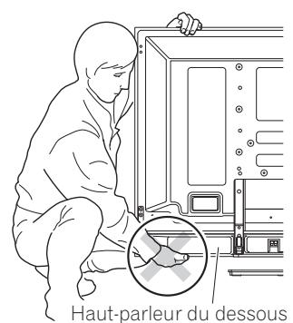
natural_image
Line drawing of a person in protective suit working on equipment inside a device (no text or symbols)natural_image
Line drawing of a server rack with connected cables and connectors (no text or symbols)natural_image
Technical line drawing of railway tracks with overhead cable and support structures (no text or symbols)natural_image
Technical line drawing of a mechanical assembly with no visible text or symbolsnatural_image
Technical line drawing of a mechanical clamp or bracket assembly (no text or symbols)natural_image
Technical line drawing of a mechanical assembly with screws and mounting brackets (no text or symbols)
Attention
natural_image
Technical line drawing of a mechanical assembly with mounting brackets and bolts (no text or symbols)natural_image
Technical line drawing of a mechanical support bracket with mounting holes and a curved component (no text or symbols)natural_image
Technical line drawing of two rectangular metal bars with holes, no text or symbols presentnatural_image
Technical line drawing of two rectangular metal bars with holes, no text or symbols presentnatural_image
Pure electrical circuit lines without any symbols- Maulschlüssel (10 mm): 1
natural_image
Line drawing of a person installing or adjusting a device panel (no text or symbols present)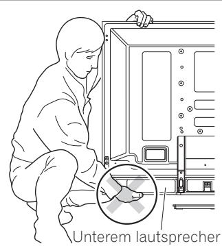
natural_image
Line drawing of a person in protective suit working on a device panel (no text or symbols)natural_image
Diagram of a server rack with connected cables and connectors (no text or labels)natural_image
Technical line drawing of railway tracks with overhead cable and support structures (no text or symbols)natural_image
Technical line drawing of a mechanical assembly with no visible text or symbolsnatural_image
Technical line drawing of a mechanical clamp or bracket assembly (no text or symbols)natural_image
Technical line drawing of a mechanical assembly with screws and mounting brackets (no text or symbols)
Hinweis
natural_image
Technical line drawing of a mechanical assembly with mounting brackets and bolts (no text or symbols)natural_image
Technical line drawing of a mechanical support bracket with mounting holes and a curved component (no text or symbols)natural_image
Technical line drawing of two rectangular metal beams with holes, no text or symbols presentnatural_image
Technical line drawing of two rectangular metal plates with holes, no text or symbols presentnatural_image
Pure electrical circuit lines without any symbolsnatural_image
Line drawing of a person installing or adjusting a device on a cabinet (no text or symbols)
natural_image
Line drawing of a person in protective suit working on a device panel (no text or symbols)natural_image
Line drawing of a server rack with connected cables and connectors (no text or symbols)natural_image
Technical line drawing of railway tracks with overhead cable and support structures (no text or symbols)natural_image
Technical line drawing of a mechanical assembly with no visible text or symbolsnatural_image
Technical line drawing of a cable clamp or connector assembly (no text or symbols)natural_image
Technical line drawing of a mounted electronic panel with screw holes and mounting brackets (no text or symbols)
Attenzione
natural_image
Technical line drawing of a mechanical assembly with mounting brackets and bolts (no text or symbols)natural_image
Technical line drawing of a mechanical support bracket with mounting holes and a curved component (no text or symbols)natural_image
Technical line drawing of two rectangular metal bars with holes, no text or symbols presentnatural_image
Technical line drawing of two rectangular metal bars with holes, no text or symbols presentnatural_image
Pure electrical circuit lines without any symbols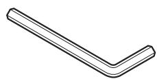
- Moersleutel x 1 (10 mm)
natural_image
Line drawing of a person installing or adjusting a device panel (no text or symbols present)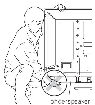
natural_image
Line drawing of a person inspecting an onderspeaker device (no text or symbols present)natural_image
Line drawing of a person in protective suit working on a device panel (no text or symbols)natural_image
Technical line drawing of a mechanical assembly with angular dimensions (10°) and alignment markers, no readable text or symbols.natural_image
Diagram of a server rack with connected cables and connectors (no text or labels)natural_image
Technical line drawing of railway tracks with overhead cable and support structures (no text or symbols)natural_image
Technical line drawing of a mechanical assembly with no visible text or symbolsnatural_image
Technical line drawing of a cable clamp assembly (no text or symbols)natural_image
Technical line drawing of a mechanical assembly with mounting brackets and screws (no text or symbols)
Waarschuwing
natural_image
Technical line drawing of a mechanical assembly with mounting brackets and bolts (no text or symbols)natural_image
Technical line drawing of a mechanical support bracket with mounting holes and a curved component (no text or symbols)natural_image
Technical line drawing of two rectangular metal beams with holes, no text or symbols presentnatural_image
Technical line drawing of two rectangular metal bars with holes, no text or symbols presentnatural_image
Pure electrical circuit lines without any symbolsnatural_image
Technical illustration of a mechanical assembly with an inset showing a bracket and a downward arrow indicating motion (no text or symbols present)natural_image
Line drawing of a person installing or adjusting equipment on a device panel (no text or symbols)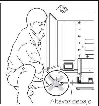
natural_image
Line drawing of a person in protective suit working on a device panel (no text or symbols)natural_image
Diagram of an electronic device showing connections between ports and cables (no text or labels)natural_image
Technical line drawing of railway tracks with overhead cable and support structures (no text or symbols)natural_image
Technical line drawing of a mechanical assembly with no visible text or symbolsnatural_image
Technical line drawing of a mechanical clamp or bracket assembly (no text or symbols)natural_image
Technical line drawing of a mounted electronic panel with screws and mounting brackets (no text or symbols)
Precaución
natural_image
Technical line drawing of a mechanical assembly with mounting brackets and bolts (no text or symbols)natural_image
Technical line drawing of a mechanical support base with mounting brackets (no text or symbols)natural_image
Technical line drawing of two rectangular metal plates with holes, no text or symbols presentnatural_image
Technical line drawing of two rectangular metal plates with holes, no text or symbols presentnatural_image
Pure electrical circuit lines without any symbols• C 型扳手 x 1 (10 mm)
· 安装螺絲 ③
natural_image
Line drawing of a person in protective suit working on equipment (no text or symbols)安裝的預防措施
natural_image
Diagram of a server rack with connected cables and connectors (no text or labels)使用線捆
natural_image
Technical line drawing of railway tracks with overhead cable and support structures (no text or symbols)3 將線捆扣上。
natural_image
Technical line drawing of a mechanical assembly with no visible text or symbols◆ 移除線捆
依圖所示的箭頭方向推開線捆,使其鬆開。
natural_image
Technical line drawing of a mechanical clamp or bracket assembly (no text or symbols)預防設備翻覆
natural_image
Technical line drawing of a computer monitor rear panel with screw holes and mounting brackets (no text or symbols)
注意
natural_image
Technical line drawing of a mechanical assembly with mounting brackets and bolts (no text or symbols)從支架拆卸先鋒電視

natural_image
Technical line drawing of a mechanical support bracket with mounting holes and a curved component (no text or symbols)natural_image
Technical line drawing of two rectangular metal beams with holes, no text or symbols presentnatural_image
Technical line drawing of two rectangular metal bars with circular holes, no text or symbols presentnatural_image
Pure electrical circuit lines without any symbols
natural_image
Line drawing of a person installing or adjusting a device on a computer chassis (no text or symbols)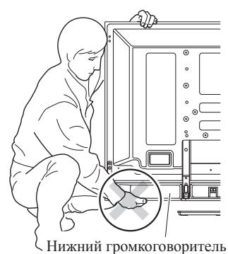
natural_image
Line drawing of a person installing or adjusting a device panel (no text or symbols present)natural_image
Diagram of a server rack with connected cables and connectors (no text or labels)natural_image
Technical line drawing of railway tracks with overhead cable and support structures (no text or symbols)natural_image
Technical line drawing of a mechanical assembly with rods and a clamp, no text or symbols presentnatural_image
Technical line drawing of a mechanical clamp or bracket assembly (no text or symbols)natural_image
Technical line drawing of a mechanical assembly with screws and mounting brackets (no text or symbols)
Внимание
natural_image
Technical line drawing of a mechanical assembly with mounting brackets and bolts (no text or symbols)PIONEER ELECTRONICS (USA) INC.
P.O. BOX 1540, Long Beach, California 90801-1540, U.S.A. TEL: (800) 421-1404
PIONEER ELECTRONICS OF CANADA, INC.
300 Allstate Parkway, Markham, Ontario L3R 0P2, Canada TEL: 1-877-283-5901, 905-479-4411
PIONEER EUROPE NV
Haven 1087, Keetberglaan 1, B-9120 Melsele, Belgium TEL: 03/570.05.11
PIONEER ELECTRONICS ASIACENTRE PTE. LTD.
253 Alexandra Road, #04-01, Singapore 159936 TEL: 65-6472-7555
PIONEER ELECTRONICS AUSTRALIA PTY. LTD.
178-184 Boundary Road, Braeside, Victoria 3195, Australia, TEL: (03) 9586-6300
PIONEER ELECTRONICS DE MEXICO S.A. DE C.V.
Blvd.Manuel Avila Camacho 138 10 piso Col.Lomas de Chapultepec, Mexico, D.F. 11000 TEL: 55-9178-4270
K002_Ru

PRINTED WITH SOYINK
Published by Pioneer Corporation.
Copyright © 2008 Pioneer Corporation.
All rights reserved.
Publication de Pioneer Corporation.
© 2008 Pioneer Corporation.


- Installation
- IMPORTANT NOTICE
- Contents
- CAUTION
- Cautions
- Installation Location
- Assembling and Installation
- Checking the Enclosed Parts
- Assembling the Stand
- Note
- Assembly Procedure
- Select the support columns to attach.
- Secure the support column to the stand with the Installation screws ① (4 locations on the left and right).
- Fully tighten the Installation screws (4 locations on the left and right).
- Attaching the Pioneer Television
- Attachment Method
- Attaching the Pioneer television to the stand.
- Securing the Pioneer television with Installation screws ②.
- Securing the Pioneer television with Installation screws ③.
- Attaching the speakers.
- Forward/Backward Angle of Inclination Adjustment Mechanism
- Adjustment Procedure
- Loosen the forward/backward inclination anchor bolts using the enclosed C wrench (2 locations on the left and right).
- Set the angle you prefer.
- Tighten the forward/backward inclination anchor bolts (2 locations on the left and right).
- Check once more to make sure that the forward/backward inclination anchor bolts are fully tightened.
- Installing the Product on a TV table etc.
- Precautions when moving
- Precautions when installing in a TV table or other enclosure
- Installation precautions
- Preparing the Cables
- Using the cable binders
- Preventing Equipment from Falling Over
- Stabilizing on TV table or other location
- Using a wall for stabilization
- Fixing the rotation to the front
- Detaching the Pioneer Television from the Stand
- Specifications
- Dimensions Diagram
- inch display model (under speaker models)
- inch display model (except under speaker models)
- Attention
- Hinweis
- Attenzione
- Waarschuwing
- Precaución
- 安裝的預防措施
- 使用線捆
- ◆ 移除線捆
- 預防設備翻覆
- 注意
- 從支架拆卸先鋒電視
- Внимание
- PIONEER ELECTRONICS (USA) INC.
- PIONEER ELECTRONICS OF CANADA, INC.
- PIONEER EUROPE NV
- PIONEER ELECTRONICS ASIACENTRE PTE. LTD.
- PIONEER ELECTRONICS AUSTRALIA PTY. LTD.
- PIONEER ELECTRONICS DE MEXICO S.A. DE C.V.
Brand : PIONEER
Model : PDK-TS36B
Category : Audio System