
PDK-TS05 - Audio accessory PIONEER - Free user manual and instructions
Find the device manual for free PDK-TS05 PIONEER in PDF.

| Product type | Plasma screen table stand |
| Brand | Pioneer |
| Model | PDK-TS05 |
| Dimensions (W x H x D) | 577 x 351 x 380 mm (with L columns) |
| Weight | 9.5 kg |
| Material | Metal (steel) |
| Screen compatibility | Pioneer plasma: PDP-505XDE, PDP-505HDE, PDP-505HDG, PDP-435XDE, PDP-435HDE, PDP-435FDE, PDP-435HDG, PDP-504HD, PDP-5040HD, PDP-504HDE, PDP-504HDG, PDP-504HDC, PDP-5045HD, PDP-434HD, PDP-4340HD, PDP-434HDE, PDP-434HDG, PDP-434HDC, PDP-4345HD |
| Tilt | 2° forward and backward |
| Swivel | 10° to the left |
| Total height (with 50" screen) | 910 mm (L columns) |
| Total height (with 43" screen) | 825 mm (L columns) |
| Maximum load | Approximately 40 kg (50" screen) / 30 kg (43" screen) |
| Number of persons required for installation | Minimum 2 persons |
| Package contents | Table stand x1, S columns x2, L columns x2, spacer parts x2, cable ties x2, installation screws (4x M8x16, 2x M8x30, 2x M8x40), hex keys (2 sizes), instruction manual |
| Main features | Stable stand, tilt and swivel adjustment, cable management, tip-over prevention |
| Maintenance and cleaning | Clean with a soft, dry cloth. Do not use solvents. |
| Safety | Mandatory installation on a flat, stable surface. Use the anti-tip devices provided or sold separately. |
| Spare parts and repairability | Contact the retailer for parts. Do not modify the stand. |
Frequently Asked Questions - PDK-TS05 PIONEER
User questions about PDK-TS05 PIONEER
0 question about this device. Answer the ones you know or ask your own.
Ask a new question about this device
Download the instructions for your Audio accessory in PDF format for free! Find your manual PDK-TS05 - PIONEER and take your electronic device back in hand. On this page are published all the documents necessary for the use of your device. PDK-TS05 by PIONEER.
USER MANUAL PDK-TS05 PIONEER
Operating instructions
Mode d'emploi
Bedienungsanleitung
本製品は左右10°回軸、前後2°傾斜いたします。本製品お願い please please please please please please please please please please please please please please please please please please please please please please please please please please please please please please please please please please please please please please please please please please please please please please please please please please please please please please please please please please please please please please please please please please please please please please please please please please please please please please please please please please please please please please please please please please please please please please please please please please please pleasepleasepleasepleasepleasepleasepleasepleasepleasepleasepleasepleasepleasepleasepleasepleasepleasepleasepleasepleasepleasepleasepleasepleasepleasepleasepleasepleasepleasepleasepleasepleasepleasepleasepleasepleasepleasepleasepleasepleasepleasepleasepleasepleasepleasepleasepleasepleasepleasepleasepleasepleasepleasepleasepleasepleasepleasepleasepleasepleasepleasepleasepleasepleasepleasepleasepleasepleasepleasepleasepleasepleasepleasepleasepleasepleasepleasepleasepleasepleasepleasepleasepleasepleasepleasepleasepleasepleasepleasepleasepleasepleasepleasepleasepleasepleasepleasepleasepleasepleasepleasePlease Please Please Please Please Please Please Please Please Please Please Please Please Please Please Please Please Please Please Please Please Please Please Please Please Please Please Please Please Please Please Please Please Please Please Please Please Please Please Please Please Please Please Please Please Please Please Please Please Please Please Please Please Please Please Please Please Please Please Please Please Please Please Please Please Please Please Please Please Please Please Please Please Please Please Please Please Please Please Please Please Please Please Please Please Please Please Please Please Please Please Please Please Please Please Please Please Please Please Please PleasePleasePleasePleasePleasePleasePleasePleasePleasePleasePleasePleasePleasePleasePleasePleasePleasePleasePleasePleasePleasePleasePleasePleasePleasePleasePleasePleasePleasePleasePleasePleasePleasePleasePleasePleasePleasePleasePleasePleasePleasePleasePleasePleasePleasePleasePleasePleasePleasePleasePleasePleasePleasePleasePleasePleasePleasePleasePleasePleasePleasePleasePleasePleasePleasePleasePleasePleasePleasePleasePleasePleasePleasePleasePleasePleasePleasePleasePleasePleasePleasePleasePleasePleasePlease请 -: 8-

注意
Thank you for buying Pioneer's product.
Please read through the Operating Instructions to learn how to operate your model safely and properly.
Please be advised to keep the Operating Instructions in your place for future reference.
Installation
- Consult your dealer if you encounter any difficulties with this installation.
- Pioneer is not liable for any damage resulting from improper installation, improper use, modification, or natural disasters.
Contents
Cautions 14
Checking the Enclosed Parts 15
Support Columns/Spacers
Used/Not Used Table 15
Assembling the Stand 16
Attaching the Plasma Display 17
Forward/Backward Angle of Inclination
Adjustment Mechanism 18
Installing the Product on a Rack etc. 19
Preparing the Cables 20
Preventing Equipment from Falling Over 21
Detaching the Plasma Display from the Stand .... 22
Specifications 22
Dimensions Diagram 22

CAUTION
This symbol refers to a hazard or unsafe practice which can result in personal injury or property damage.
Cautions

This product is a table top stand exclusively designed for plasma displays (PDP-505XDE / PDP-505HDE / PDP-505HDG / PDP-435XDE / PDP-435HDE / PDP-435FDE / PDP-435HDG / PDP-504HD / PDP-5040HD / PDP-504HDE / PDP-504HDG / PDP-504HDC / PDP-5045HD / PDP-434HD / PDP-4340HD /PDP-434HDE / PDP-434HDG / PDP-434HDC / PDP-4345HD) from Pioneer. Use with other model is capable of resulting in instability causing possible injury. For further information, please contact the store where you purchased your display.
Do not install or modify the product other than specified.
Do not use this stand for a plasma display other than those designated and do not modify it or use it for other purposes.
Improper installation is extremely dangerous because it may result in it falling over or other accident.
Installation Location
- Select a location that is strong enough to support the weight of the stand and the displays.
- Make sure to place it in a level and stable location.
- Do not install it outdoors, at a hot spring, or near a beach.
- Do not install the stand where it may be subjected to vibration or shock.
Assembling and Installation
- Assemble the stand in accordance with the assembly instructions and securely attach all screws at the designated locations. There have been cases where unforeseen accidents such as the equipment breaking or falling over occurred after the installation of the display because the stand was not installed as instructed.
- The display must always be installed by two or more people to assure it is installed safely.
- Before installation, turn off the power for the display and peripheral devices then remove the power cord plug from the power outlet.
This product rotates 10^ to the left and right and inclines 2^ forward and backward.
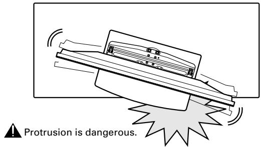
Do not place objects within the range of rotation of this product and the plasma display. Install this product so that during routine use or when it is rotated, it does not protrude from the rack or other location it has been installed. Failure to do so could cause unforeseen accidents such as the equipment breaking or falling over (see page 19).
Prevent accidents caused by the product falling over by taking reliable measures to prevent it from falling over (see Page 21).
Checking the Enclosed Parts
Check to make sure that you have all the enclosed parts before assembly and installation.
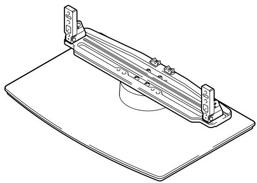
- Table top stand x 1
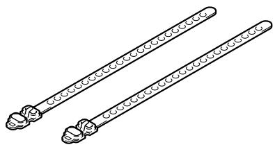
- Cable binders x 2
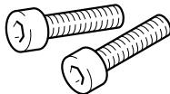
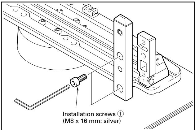
- Installation screws ① (M8 x 16 mm: silver) x 4 [used to anchor the support columns and the table top stand]
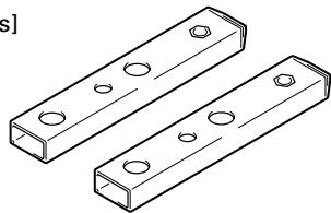
- Support columns S x 2 [short columns]

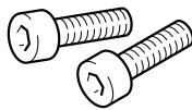
- Installation screws ② (M8 x 30 mm: black) x 2
- Installation screws ③ (M8 x 40 mm: black) x 2
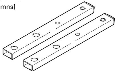
- Support columns L x 2 [long columns]
- Operating instructions (this document) x 1
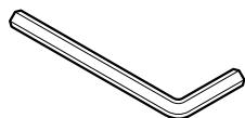
- Hexagonal wrench x 1 (Diagonal size: 6mm )
- Spacers × 2

C wrench x 1 (10 mm)
Support Columns/Spacers Used/Not Used Table
The parts of this stand that are used vary depending on the speakers that you have purchased and on their installation location on the plasma display. Please select the parts you use according to the following table.
| Combined speaker numbers | Speaker installation location | Support columns S (short columns) | Support columns L (long columns) | Spacers |
| Not used | - | Recommended | Can be used* | Cannot be used |
| PDP-S21-LRPDP-S22-LR | Both sides of the plasma display (or not used) | Recommended | Can be used* | Cannot be used |
| Bottom of the plasma display | Cannot be used | Used | Used | |
| PDP-S25-LRPDP-S26-LR | Both sides of the plasma display (or not used) | Recommended | Can be used* | Cannot be used |
*: Can be used when the screen is located in a high position.
Assembling the Stand
Note
- Always assemble it on a flat table etc.
- Insert the screws in the holes vertically and do not tighten them with more force than necessary.
Assembly Procedure
1 Select the support columns to attach.
Select the support columns according to the settings of the speakers that you have purchased with reference to the following stipulation (Only one type of the two types of available support columns should be used).
When the speakers you have purchased are PDP-S25-LR or PDP-S26-LR.
[Support column used: support column S (short columns)]
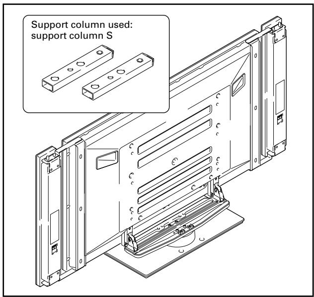
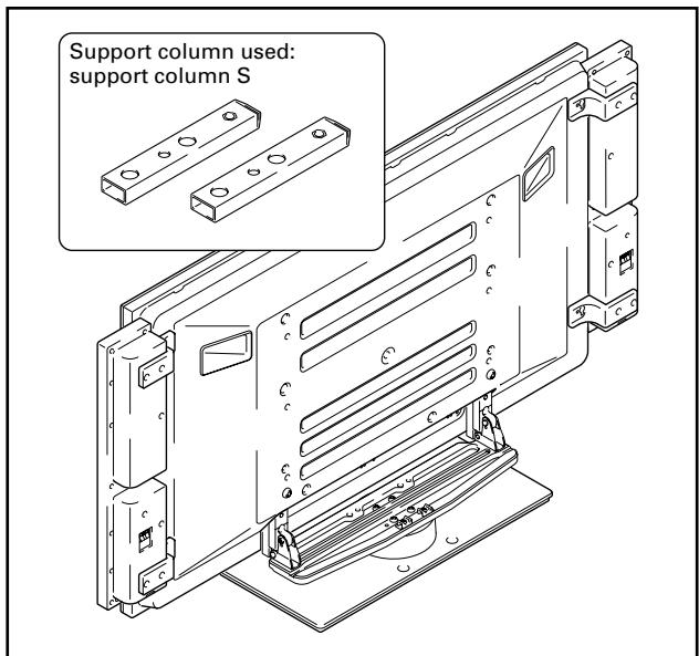
When the speakers you have purchased are PDP-S21-LR or PDP-S22-LR.
When installing speakers on both sides of the plasma display [Support column used: support column S (short columns)]
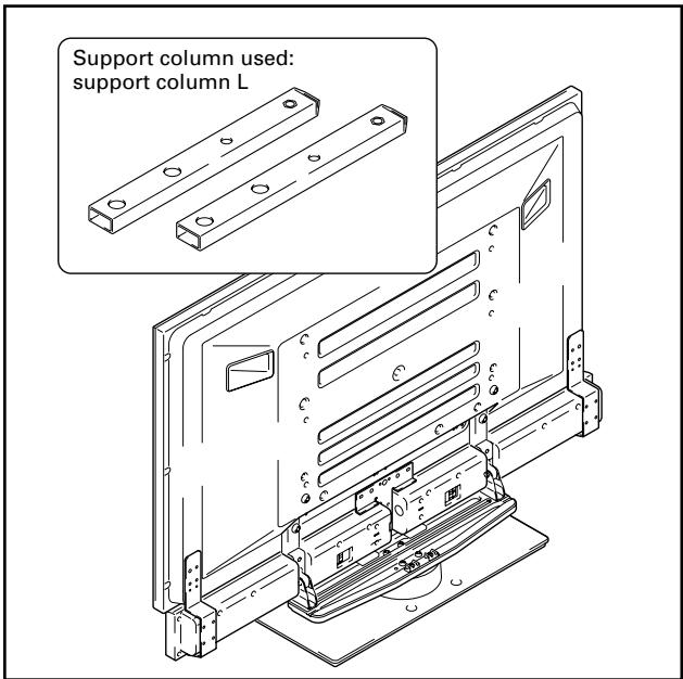
When installing speakers at the bottom of the plasma display [Support column used: support column L (long columns)]
Note
The PDP-S25-LR and PDP-S26-LR cannot be installed at the bottom of the plasma display.
2 Secure the support column to the stand with the Installation screws (1) (4 locations on the left and right).
Using the enclosed hexagonal wrench, first loosely attach the top attachment screw, then loosely attach the bottom attachment screw.
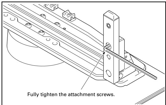
3 Fully tighten the Installation screws (4 locations on the left and right).
Attaching the Plasma Display

The weight of a 50 inch plasma display is about 40kg (88 lbs), that of a 43 inch model is about 30kg (66 lbs), they have no depth, and are unstable. Therefore, at least two people must assemble and install them.
Note
- Be sure to install it on a flat stable location.
- Insert the screws in the holes vertically and do not tighten them with more force than necessary.
- Make sure that you install the support columns reliably according to the settings of the type of speakers you have purchased with reference to the procedure in Assembling the Stand.
Attachment Method
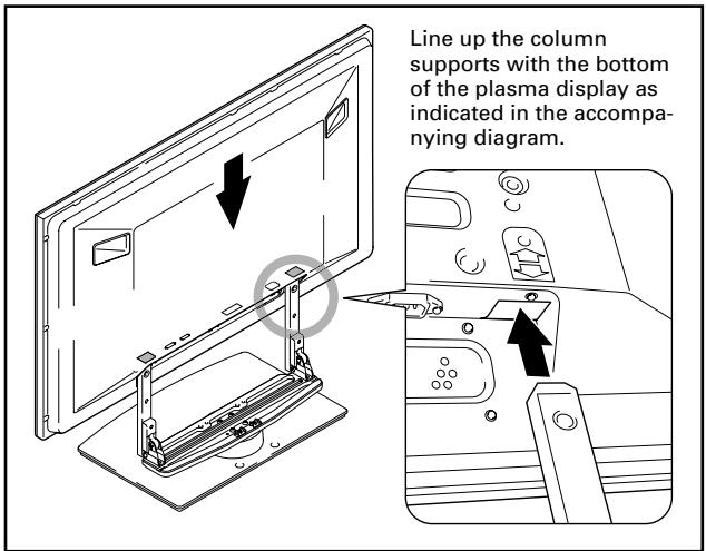
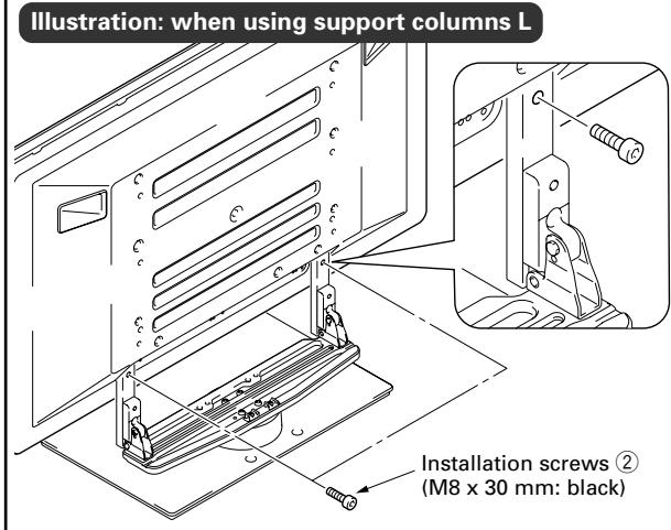
1 Attaching the plasma display to the stand.
Fit the stand's support columns to the bottom of the plasma display as indicated by the arrows, then slowly insert them vertically. Be extremely careful not to insert the support columns of the stand into any part of the plasma display other than the stand insertion slots. Note that doing so might damage the plasma display panel or its ports or result in the warping of the stand.
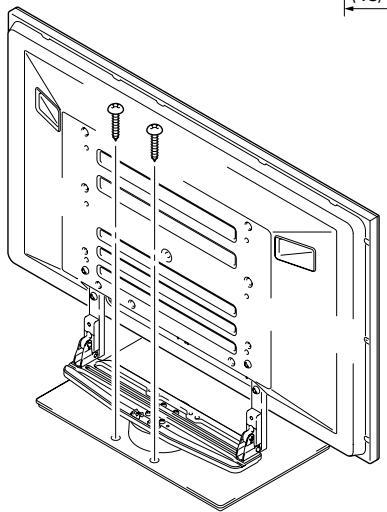
2 Securing the plasma display with Installation screws ②.
Secure them using the enclosed hexagonal wrench.
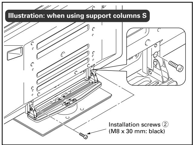
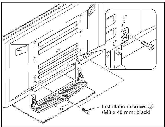
3 Securing the plasma display with Installation screws ③.
Attach the plasma display at the points indicated by the arrows using the enclosed hexagonal wrench.
Only when attaching speakers at the bottom of the plasma display
4 Inserting the spacers.
Insert the spacers in the holes on the rotating platform of the stand.
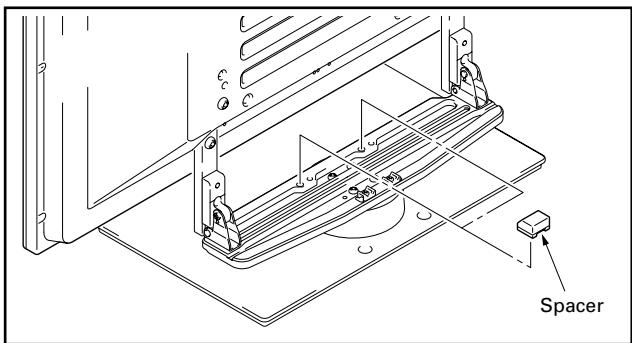
Note
Please do not use the spacer if the speakers are to be attached to both sides of the plasma display.
5 Attaching the speakers.
Refer to the operating instructions for the speaker for the installation method.
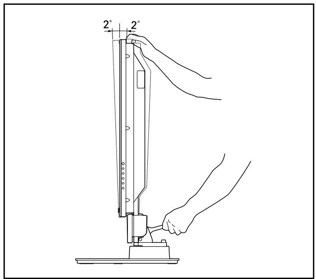
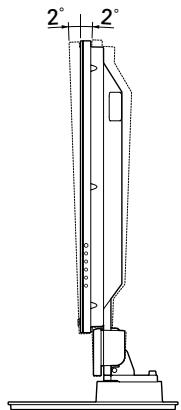
Forward/Backward Angle of Inclination Adjustment Mechanism
On this stand, you can adjust the angle of inclination of the plasma display within a range of 2^ forward or backward according to your preference.
Note
- Be sure to adjust the angle only after you have attached the plasma display.
- Be sure to install it on a flat table or other flat surface.
- Be sure to hold the top of the plasma display with your hand while adjusting the angle.
Adjustment Procedure
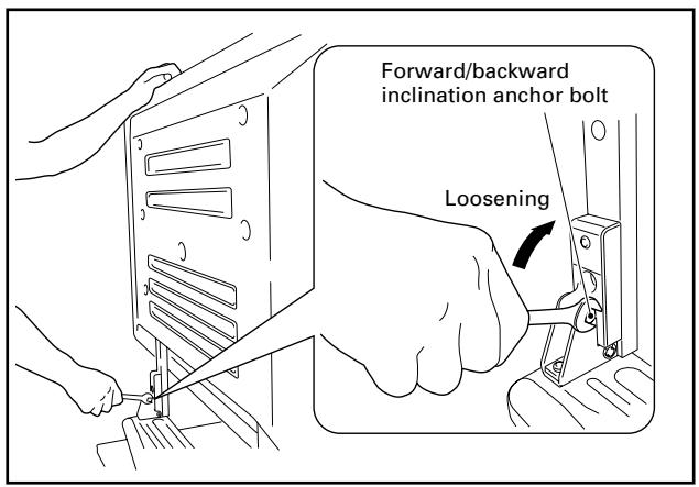
1 Loosen the forward/backward inclination anchor bolts using the enclosed C wrench.
While being sure to hold the top of the plasma display with your hand, loosen the forward/backward inclination anchor bolts on the left and right sides by rotating them upwards using the enclosed C wrench.
2 Set the angle you prefer.
Set the angle you prefer by slowly moving the plasma display.
3 Tighten the forward/backward inclination anchor bolts.
Firmly tighten the forward/backward inclination anchor bolts on the left and right sides by rotating them downward using the enclosed C wrench. Be sure to hold the top of the plasma display with your hand until you have fully tightened the bolts.
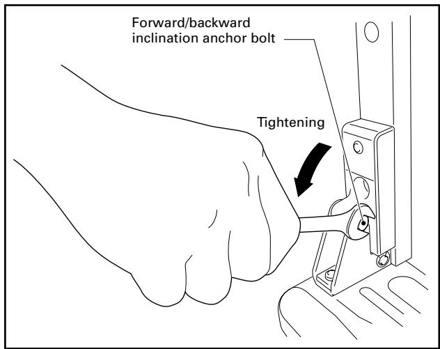
4 Check once more to make sure that the forward/backward inclination anchor bolts are fully tightened.
Installing the Product on a Rack etc.
Be sure to observe the following precautions when moving or installing this product with a plasma display into a rack or other enclosure.
Precautions when moving

- When moving the product more than a few meters, first remove the speaker, then remove the plasma display from the stand and move the speaker, plasma display, and stand separately.
- When detaching the plasma display from the stand, be sure to follow the procedure described in "Detaching the Plasma Display from the Stand" on page 22.
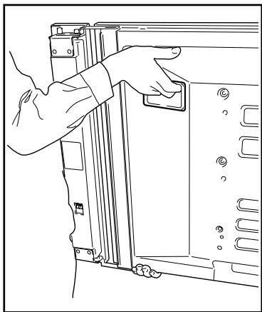
Precautions when installing in a rack or other enclosure

When installing in a rack or other enclosure, hold the plasma display by the handles located on the rear and bottom of the plasma display. If you hold the speakers, they may be damaged or twisted.
When installing speakers on both sides of the plasma display
Hold the plasma display by its handles and from the bottom.
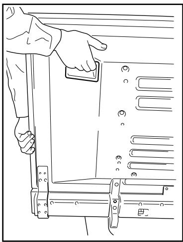
When installing speakers at the bottom of the plasma display
Hold the plasma display by its handles and from the sides.
Installation precautions
Make sure that you always secure a space at least as large as that shown in the following diagram in front of and behind the table top stand.
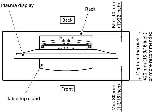

- If the stand protrudes from the rack, it could cause unforeseen accidents such as the equipment breaking or falling over.
- When rotating, take care not to allow the display to bump into walls or surrounding objects.
Range of angle rotation

Forward/backward angle of inclination adjustment range
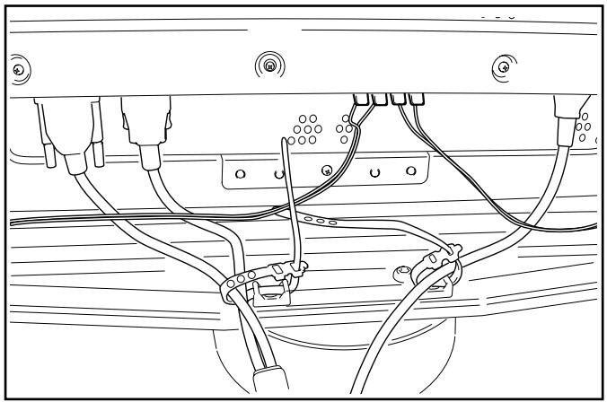
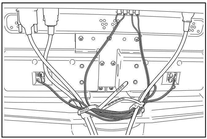
Preparing the Cables
Use the enclosed cable binders to bind the cables.
Note
Be very careful not to apply force to the bases of the cables.
When installing speakers on both sides of the plasma display
When installing speakers at the bottom of the plasma display
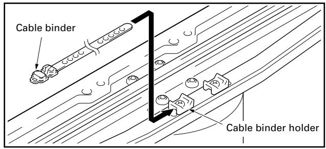
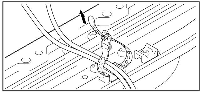
Using the cable binders
1 Passing a cable binder though the cable binder holder on the top of the rotating platform of the stand.
2 Gathering cables and placing them on the cable binder.
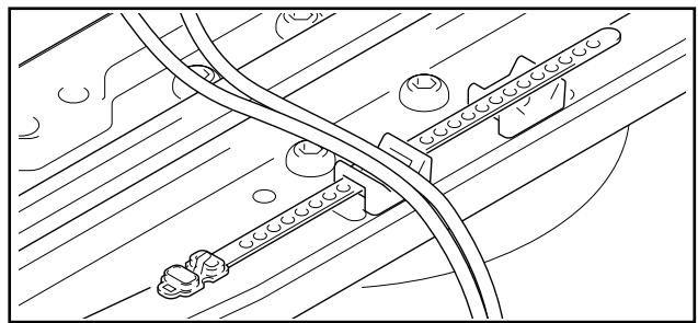
3 Passing the cable binder through the hole on its end.
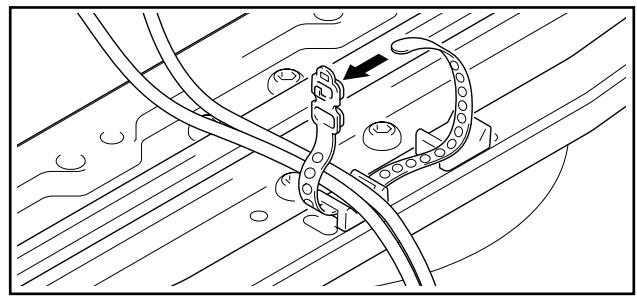
4 Pulling the end of the cable binder to secure the cables.
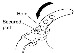
Removing a cable binder If the secured part is removed from the cable binder hole, it is unlocked.
Preventing Equipment from Falling Over
After installing the stand, be sure to take measures so that the equipment will not fall over.
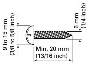
Stabilizing on the floor
Stabilize the equipment as shown in the diagram using screws that are available on the market.
Note
To stabilize the equipment on the floor use screws that have a nominal diameter of 6mm (1/4 inch) and that are at least 20mm (13/16 inch) long.
Position of floor screws: Without speakers
Unit: mm (inch)
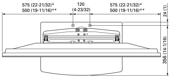
: 50 inch display model
*: 43 inch display model
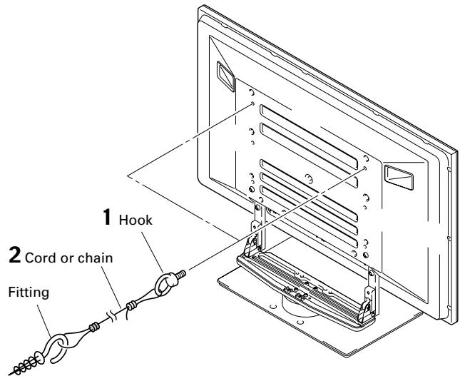
Using a wall for stabilization
(43 inch display model in the figure)
1 Attaching falling prevention bolts (hooks) to the plasma display.
2 Using strong cords or chains to firmly stabilize it to a wall, pillar, or other sturdy element.
- Perform this work in the same way on the left and right sides.
- The length of the cords or chains used must be long enough to allow the stand to rotate freely.
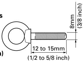
Note
Use hooks, ropes, chains, and fittings that are available on the market.
Recommended hook:
Nominal diameter 8 mm (3/8 inch) Length 12 to 15 mm (1/2 to 5/8 inch)
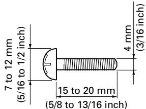
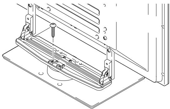
Fixing the rotation to the front
Stabilize the equipment as shown in the diagram using screws that are available on the market.
Note
Use a screw that has a nominal diameter of 4 mm (3/16 inch) and length from 15 to 20 mm (5/8 to 13/16 inch) to fix the rotation to the front.
Detaching the Plasma Display from the Stand

To remove the plasma display from the stand, be sure to always follow the procedure described below to prevent accidents
1 First, confirm that the forward/backward inclination anchor bolt is securely tightened.
2 First clear a space on a flat floor etc. where you can lay the plasma display flat, then lay a sheet to protect it from scratches or other damage.
3 Remove the speakers.
4 Referring to steps 2 and 3 in Attaching the Plasma Display (Page 17.), remove the black screws (4 screws).
Note
Do not remove the silver screws. If you do, the column supports might slip out of place and fall over.
5 Holding the plasma display by its handles and from the bottom, lift the display vertically.
6 Place the plasma display slowly onto the sheet laid out in step 2 with its screen facing downwards.
Note
When reattaching the plasma display to the stand, be certain that the left/right support columns are set at the same angle.
Specifications
External dimensions 577 (W) x 351 (H) x 380 (D) mm (22-3/4 (W) x 13-7/8 (H) x 15 (D) in.)
[When using the support columns L]
Weight 9.5 kg (20.16 lbs)
- The above specifications and exterior may be modified without prior notice to improve the product.
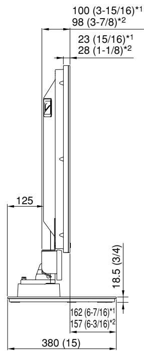
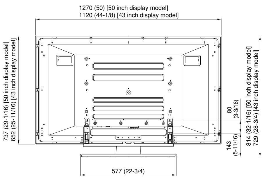
Dimensions Diagram
Unit: mm (inch)
The illustration measurements do not include the fixtures for attaching the speakers.
When installing the PDP-S25-LR or the PDP-S26-LR speakers
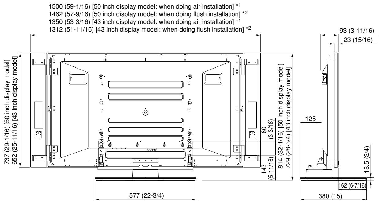
- When using the support columns L, the height is 910 (35-7/8) [50 inch display model] / 825 (32-1/2) [43 inch display model].
1 Air installation: Attached to allow adjustment of the speaker angle
2 Flush installation: Attached to fix the speaker angle and give the system a more compact width
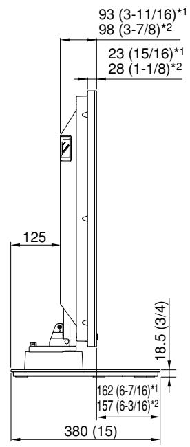
When installing speakers on both sides of the plasma display
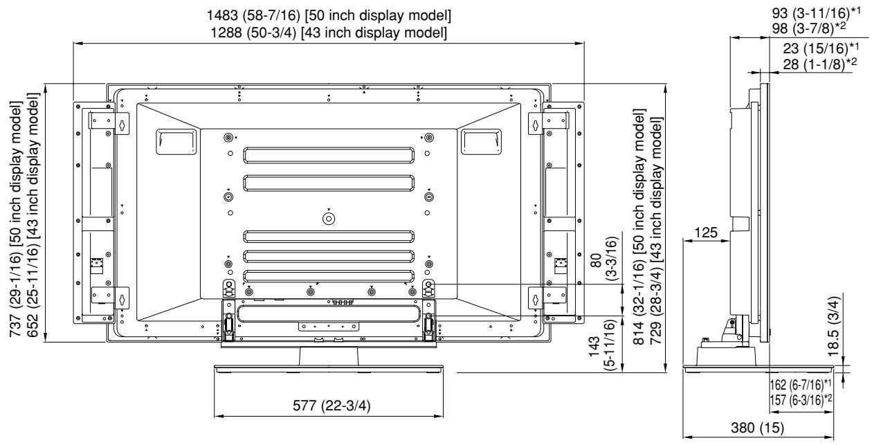
- When using the support columns L, the height is 910 (35-7/8) [50 inch display model] / 825 (32-1/2) [43 inch display model].
When installing speakers at the bottom of the plasma display
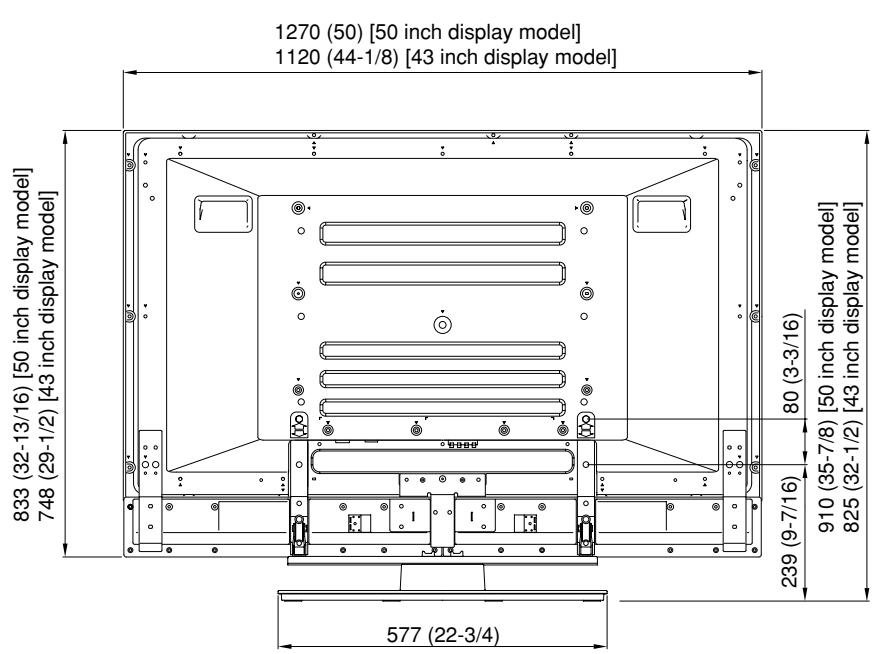
1 ....... PDP-505XDE/505HDE/505HDG/435XDE/435HDE/435FDE/435HDG
2 ....... PDP-504HD/5040HD/504HDE/504HDG/504HDC/5045HD/434HD/4340HD/434HDE/434HDG/434HDC/4345HD
- When using the support columns L, the height is 910 (35-7/8) [50 inch display model] / 825 (32-1/2) [43 inch display model].
1 ....... PDP-505XDE/505HDE/505HDG/435XDE/435HDE/435FDE/435HDG
2 ...... PDP-504HD/5040HD/504HDE/504HDG/504HDC/5045HD/434HD/4340HD/434HDE/434HDG/434HDC/4345HD
- Maulschlüssel x 1 (10 mm)
Preventing Equipment from Falling Over 76
Preventing Equipment from Falling Over
AFTER-SALES SERVICE FOR PIONEER PRODUCTS
Please contact the dealer or distributor from where you purchased the product for its after-sales service (including warranty conditions) or any other information. In case the necessary information is not available, please contact the Pioneer's subsidiaries (regional service headquarters) listed below:
PLEASE DO NOT SHIP YOUR PRODUCT TO THE COMPANIES at the addresses listed below for repair without advance contact, for these companies are not repair locations.
AMERICA
PIONEER ELECTRONICS (USA) INC.
CUSTOMER SUPPORT DIVISION
P.O. BOX 1760, LONG BEACH, CA 90801-1760, U.S.A.
CUSTOMER SERVICE HOTLINE : (800) 421-1404
EUROPE
PIONEER EUROPE NV
EUROPEAN SERVICE DIVISION
HAVEN 1087, KEETBERGLAAN 1, B-9120 MELSELE, BELGIUM
ASEAN
PIONEER ELECTRONICS ASIACENTRE PTE. LTD.
SERVICE DEPARTMENT
253, ALEXANDRA ROAD #04-01 SINGAPORE 159936
JAPAN AND OTHERS
PIONEER CORPORATION (HEAD OFFICE)
CUSTOMER SUPPORT CENTER
Published by Pioneer Corporation.
Copyright © 2004 Pioneer Corporation.
All rights reserved.
八才二株式会社
PIONEER ELECTRONICS (USA) INC.
P.O. BOX 1540, Long Beach, California 90810-1540, U.S.A. TEL: (800) 421-1404
PIONEER ELECTRONICS OF CANADA, INC.
300 Allstate Parkway, Markham, Ontario L3R OP2, Canada TEL: 1-877-283-5901
PIONEER EUROPE NV
Haven 1087, Keetberglaan 1, B-9120 Melsele, Belgium TEL: 03/570.05.11
PIONEER ELECTRONICS ASIACENTRE PTE. LTD.
253 Alexandra Road, #04-01, Singapore 159936 TEL: 65-6472-7555
PIONEER ELECTRONICS AUSTRALIA PTY. LTD.
178-184 Boundary Road, Braeside, Victoria 3195, Australia, TEL: (03) 9586-6300
PIONEER ELECTRONICS DE MEXICO S.A. DE C.V.
Blvd.Manuel Avila Camacho 138 10 piso Col.Lomas de Chapultepec, Mexico,D.F. 11000 TEL: 55-9178-4270


- 注意
- Installation
- Contents
- CAUTION
- Cautions
- Installation Location
- Assembling and Installation
- Checking the Enclosed Parts
- Support Columns/Spacers Used/Not Used Table
- Assembling the Stand
- Note
- Assembly Procedure
- Select the support columns to attach.
- Secure the support column to the stand with the Installation screws (1) (4 locations on the left and right).
- Fully tighten the Installation screws (4 locations on the left and right).
- Attaching the Plasma Display
- Attachment Method
- Attaching the plasma display to the stand.
- Securing the plasma display with Installation screws ②.
- Securing the plasma display with Installation screws ③.
- Only when attaching speakers at the bottom of the plasma display
- Inserting the spacers.
- Attaching the speakers.
- Forward/Backward Angle of Inclination Adjustment Mechanism
- Adjustment Procedure
- Loosen the forward/backward inclination anchor bolts using the enclosed C wrench.
- Set the angle you prefer.
- Tighten the forward/backward inclination anchor bolts.
- Check once more to make sure that the forward/backward inclination anchor bolts are fully tightened.
- Installing the Product on a Rack etc.
- Precautions when moving
- Precautions when installing in a rack or other enclosure
- When installing speakers on both sides of the plasma display
- When installing speakers at the bottom of the plasma display
- Installation precautions
- Preparing the Cables
- Using the cable binders
- Preventing Equipment from Falling Over
- Stabilizing on the floor
- Using a wall for stabilization
- (43 inch display model in the figure)
- Fixing the rotation to the front
- Detaching the Plasma Display from the Stand
- Specifications
- Dimensions Diagram
- When installing the PDP-S25-LR or the PDP-S26-LR speakers
- AFTER-SALES SERVICE FOR PIONEER PRODUCTS
- 八才二株式会社
Brand : PIONEER
Model : PDK-TS05
Category : Audio accessory