
PDK-WM02 - Audio accessory PIONEER - Free user manual and instructions
Find the device manual for free PDK-WM02 PIONEER in PDF.

| Product type | Wall mount for plasma screen |
| Brand | PIONEER |
| Model | PDK-WM02 |
| Intended use | Exclusive wall mount for Pioneer plasma screens |
| Material | Steel |
| Finish | Black |
| Mounting | Requires fixing to concrete wall or wooden frame |
| Installation | Recommended by at least two people |
| Load capacity | Up to 50 kg |
| Compatibility | Pioneer plasma screens from 50" to 65" |
| VESA standard | Up to 400 x 400 mm |
| Warranty | 2 years |
| Dimensions (W x H x D) | 680 x 450 x 80 mm |
| Bracket weight | 5.2 kg |
| Package contents | Wall mount, screws, wall plugs, instruction manual |
| Maintenance | Clean with a soft dry cloth |
| Safety | Solid fixing required, periodic inspection recommended |
| Repairability | Spare parts available on request |
| Certifications | CE, RoHS |
| Country of origin | Japan |
Frequently Asked Questions - PDK-WM02 PIONEER
User questions about PDK-WM02 PIONEER
0 question about this device. Answer the ones you know or ask your own.
Ask a new question about this device
Download the instructions for your Audio accessory in PDF format for free! Find your manual PDK-WM02 - PIONEER and take your electronic device back in hand. On this page are published all the documents necessary for the use of your device. PDK-WM02 by PIONEER.
USER MANUAL PDK-WM02 PIONEER
外形寸法図
質量
Thank you for buying Pioneer's product.
Please read through the Operating Instructions to learn how to operate your model safely and properly.
Please be advised to keep the Operating Instructions in your place for future reference.
Installation
- Consult your dealer if you encounter any difficulties with this installation.
- Pioneer is not liable for any damage resulting from improper installation, improper use, modification, or natural disasters.
Note to Construction Companies
Prior to installing this product, please read Pioneer's technical manual thoroughly and heed its content.
Pioneer shall not be liable in any way for any accidents or damage resulting from other than the specified assembly, mounting and usage, from remodeling, or from natural disasters or the like.
Contents
Cautions....9
Checking the Parts .... 10
Installation Procedure.... 10
External Dimension Diagram.... 14

CAUTION
This symbol refers to a hazard or unsafe practice which can result in personal injury or property damage.
Cautions

This product is exclusively for use with the plasma display.
It should not be used for any other purpose, such as for holding a plasma display, or remodeled in any way.
Improper installation is extremely dangerous because it may result in it falling over or other accident.
Installation Location
- Select a location that is strong enough to support the weight of the wall mount and the displays.
- Do not install it at a place where people can easily hang from it or lean on it.
- Do not install it outdoors, at a hot spring, or near a beach.
- Do not install where vibration or shock may occur.
- There are cases where it cannot be installed because of the structural strength of the wall, so consult with an expert installer.
- Thoroughly read and always follow the plasma display operating instructions for more information about the installation location.
Assembling and Installation
- Assemble in accordance with the assembly instructions and securely attach all screws at the designated locations.
There have been cases where unforeseen accidents such as the equipment breaking or falling over due to incorrect installation have occurred. - The display must always be installed by two or more people to assure it is installed safely.
- Before installation, turn off the power for the display and peripheral devices then remove the power cord plug from the power outlet.
Make sure that the screws used to attach all parts never become loose, because a loosened screw may result in it falling over or other accident.
If you discover a fault or malfunction, immediately have an expert installer perform repairs.
There is a danger of the interior of metal fittings of the display, parts attached to the wall, or other places that cannot be seen being damaged so that the display falls over. Therefore, when inspecting or repairing the display, or when performing interior finishing work in your shop, be sure to ask an expert installer to inspect these places. We recommend that if possible, you ask an expert installer to perform inspections at regular intervals.
If the metal fittings of the display are used for a long time, the environment may cause change over time, reducing their strength. After five years, ask an expert installer to inspect it to make sure that it can be used without any problems.
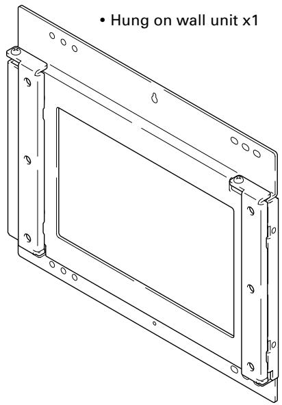
Checking the Parts
Check the parts before beginning assembly.
Note
- Screws used to fix the wall-hanging metal fitting firmly to the wall surface are not included. Purchase these separately.
● Philips driver separately.
-
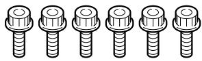
Bolts M8 x 6
-
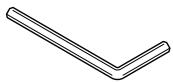
Hexagon wrench x 1 (Opposite side 6 mm for M8 use)
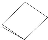
- Stencil x 1
- Operating instructions (this document) x 1
Installation Procedure
1 Removing the screws from the top and bottom of the Hung on wall unit (4 locations: top and bottom, left and right side).
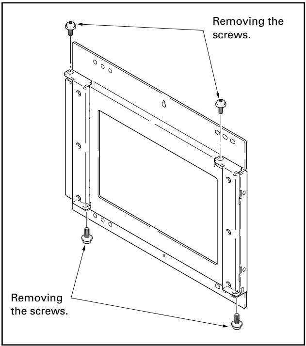
Note
Be careful not to lose the 2 anchor screws (M5 x 10mm) because they will be used later.
2 Removing the PDP side metal fitting from the wall side metal fitting.
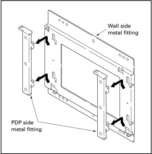
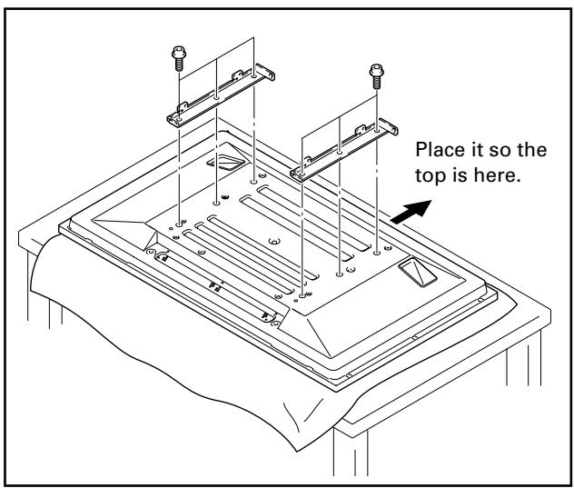
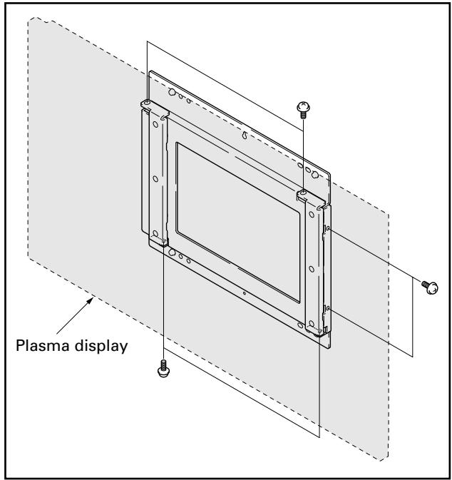
3 Attaching the PDP side metal fitting to the plasma display.
Attach the PDP side metal fitting to the plasma display with bolts M8 carefully so the top and bottom are not accidentally reversed (6 locations).
Note
- Spread a sheet or similar material so that the display will not be scratched or damaged.
● Always install it on top of a stable table or similar surface.
Note
- If you plan to install speakers, install them at this stage.
- For the installation method, refer to the speaker installation procedure in the operating instructions for the plasma display.
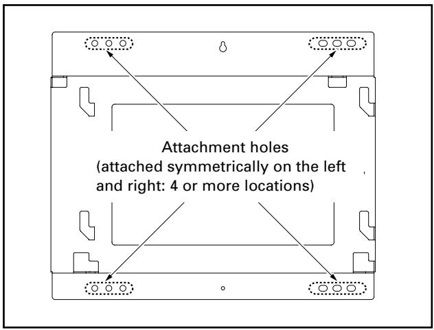
4 Installing the wall side metal fitting on the wall.
Fix it firmly in place symmetrically to the left and right (4 or more locations).
The screws and bolts used for this step vary according to the strength and the materials of the wall, so prepare these separately.
Note
Perform this installation work after confirming the strength of the wall, columns, etc.
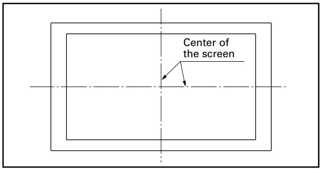
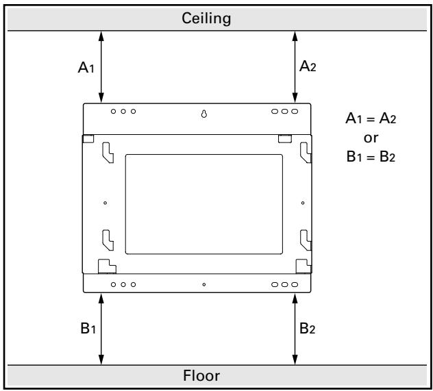
① First decide the position to install the plasma display as you check the strength of the wall and beam, then set the location at the center of the screen.
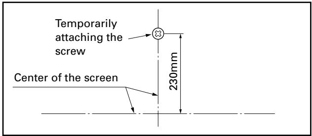
② Temporarily attach the screw used for positioning about 230mm above the center of the screen. After the metal fitting is fixed by the temporarily attached screw, remove it if it is not necessary.
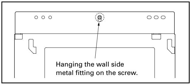
③ Hang the wall side metal fitting on the screw referred to in step ②.
④ Measure the distance from the ceiling to the wall side metal fitting (A1, A2) and the distance from the floor to the metal fitting (B1, B2), then after adjusting it so it is horizontal, fasten it to the wall with bolts.
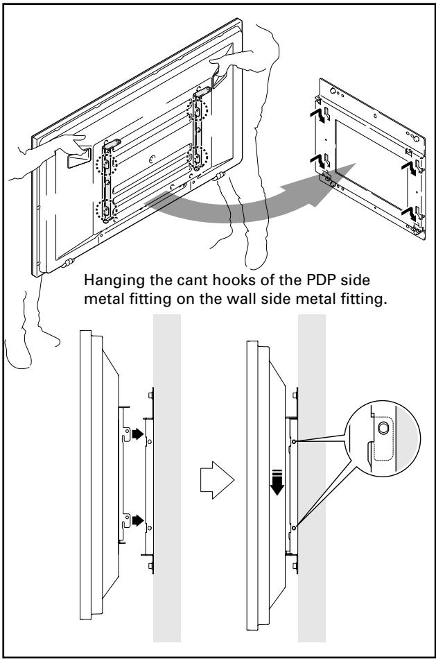
5 Hanging the cant hooks of the PDP side fitting on the wall side fitting (4 locations).
Make sure that the cant hooks are firmly hung and that the plasma display is attached horizontally in its correct position.

Caution
Always have at least two people do this task.
Note
- If speakers are attached, do not hold the speakers to perform this attachment.
- Be careful that the wiring etc. is not caught in the metal fitting or the plasma display. Be extremely careful if there is a speaker attached to the bottom, because if there is, wiring etc. is easily caught between the wall and the speaker.
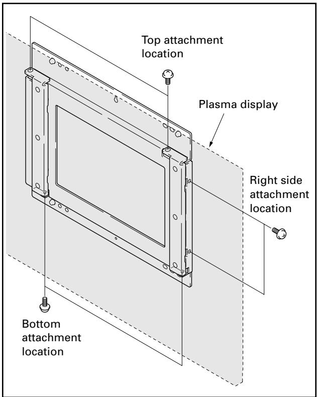
6 Fixing the metal fitting with the screws removed in step 1 (2 locations).
Select the positions to attach the screws from the top, bottom, or right side.
Attach the screws at two locations on the same plane. If there is no space above the plasma display, select locations either below or to the right of the speaker installation location.
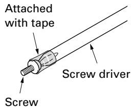
It is convenient to attach the screws using a screw driver with a magnetized tip. If you do not have one, you can do the work easily by attaching the head of the screw to the tip of the screw driver with tape so that the screw does not fall.
When removing the plasma display

Caution
Before beginning this procedure, remove the power plugs of the plasma display and peripheral devices from their outlets. As necessary also remove connecting cables.

Caution
Always have at least two people do this task.
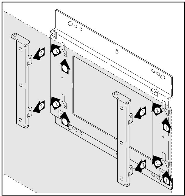
1 Removing screws fixing the PDP side metal fitting.
2 After slightly raising the plasma display once (①), raise it upwards to the left (②) till you cannot raise it any higher. You can remove it by pulling it towards yourself in this position (③).
External Dimension Diagram
Weight
- 5.2 kg (11.5 lbs) [only metal fittings]
• 35.4 kg (78.0 lbs) [When used with a PDP-435XDE/435HDE/435FDE/435HDG display with speakers (PDP-S22-LR) attached.]
• 36.6 kg (80.7 lbs) [When used with a PDP-435XDE/435HDE/435FDE/435HDG display with speakers (PDP-S26-LR) attached.] - 41.6 kg (91.7 lbs) [When used with a PDP-505XDE/505HDE/505HDG display with speakers (PDP-S21-LR) attached.]
- 42.9 kg (94.6 lbs) [When used with a PDP-505XDE/505HDE/505HDG display with speakers (PDP-S25-LR) attached.]
✿ PDP-435XDE/435HDE/435FDE/435HDG display with speakers (PDP-S22-LR) attached PDP-505XDE/505HDE/505HDG display with speakers (PDP-S21-LR) attached
![Unit. mm Dimensions in ( ) are the dimensions for the 50 inch model 98 [External dimensions when side speakers are installed] 1120 (1270) 496 455 407 355 292 (367) 76 (118.5) 257 (332) 652 (737) 250 230 150 Center line (Screen center) 225 205 150 559 (634) [External dimension of a side speaker] 96 303 268 1118 (1268) [External dimension of a bottom speaker] 1288 (1438) [External dimension of a side speaker] 475 101(143.5) 93 [Plasma display] 32 [Only metal fitting] 98](/content/2019/11/118672/images/20162428479e88b24ef673f2ffd09d611f5d27b886343285c9d5b9839b5f9824.jpg)
✿ PDP-435XDE/435HDE/435FDE/435HDG display with speakers (PDP-S26-LR) attached
PDP-505XDE/505HDE/505HDG display with speakers (PDP-S25-LR) attached
![62 1312 (1462) [When doing a flush installation] 1350 (1500) [When doing an air installation] 303 268 496 455 407 355 76 (118.5) 250 230 150 652 (737) 205 150 225 Center line (Screen center) 475 257 (332) 571 292 (367) 1120 (1270) 101 (143.5) 93 125 32 [Only metal fittings] Published by Pioneer Corporation](/content/2019/11/118672/images/249259dda645e4cb02d45e7b61df7a5304919393516ba693c277d3f6901a5f60.jpg)
Published by Pioneer Corporation.
Copyright © 2004 Pioneer Corporation.
All rights reserved.
パイオニア株式会社
PIONEER ELECTRONICS AUSTRALIA PTY.LTD. 178-184 Boundary Road, Braeside, Victoria 3195, Australia, TEL: 61-39-586-6300
PIONEER ELECTRONICS ASIACENTRE PTE. LTD. 253 Alexandra Road #04-01, Singapore 159936, TEL: 65-6472-1111
PIONEER HIGH FIDELITY TAIWAN CO., LTD. 13FL., No44 Chung Shan North Road, Sec.2. Taipei, Taiwan, TEL: 886-2-2521-3588
PIONEER ELECTRONICS (CHINA) LTD. Room 1704-06, 17/F World Trade Centre, 280 Gloucester Rd. Causeway Bay, Hong Kong, TEL: 852-2848-6488
PIONEER GULF FZE Lob 11-017, Jebel Ali Free Zone P.O. BOX 61226, Jebel Ali, Dubai, United Arab Emirates, TEL: 971-4-8815756
PIONEER ELECTRONICS DE MEXICO S.A. DE C.V. Blvd. Manuel Avila Camacho 138 10 piso Col.Lomas de Chapultepec, Mexico, D.F. 11000 TEL: 55-9178-4270

- 外形寸法図
- 質量
- Installation
- Note to Construction Companies
- Contents
- CAUTION
- Cautions
- Installation Location
- Assembling and Installation
- Checking the Parts
- Note
- Installation Procedure
- Attaching the PDP side metal fitting to the plasma display.
- Installing the wall side metal fitting on the wall.
- Hanging the cant hooks of the PDP side fitting on the wall side fitting (4 locations).
- Fixing the metal fitting with the screws removed in step 1 (2 locations).
- When removing the plasma display
- Removing screws fixing the PDP side metal fitting.
- After slightly raising the plasma display once (①), raise it upwards to the left (②) till you cannot raise it any higher. You can remove it by pulling it towards yourself in this position (③).
- External Dimension Diagram
- Weight
- パイオニア株式会社
Brand : PIONEER
Model : PDK-WM02
Category : Audio accessory