
PDK-TS10 - Audio accessory PIONEER - Free user manual and instructions
Find the device manual for free PDK-TS10 PIONEER in PDF.

| Product type | Tabletop stand for plasma screens |
| Brand | PIONEER |
| Model | PDK-TS10 |
| Compatibility | Pioneer plasma screens PDP-5050SX (50") and PDP-4350SX (43") |
| Dimensions (W x H x D) | 566 mm x 491 mm x 325 mm |
| Weight | 4.1 kg |
| Materials | Not specified (probably steel and plastic) |
| Package contents | Table cover, 2 support columns, 2 M8x20 mm screws, 2 M8x40 mm screws, 4 4x10 mm screws, hex key (6 mm), instruction manual |
| Assembly | Assembly by at least two people, installation on a flat and stable surface |
| Safety | Use 6 mm screws ≥20 mm for stabilization on table/base; hooks and chains for wall attachment (not supplied) |
| Maximum supported weight | Approximately 40 kg (50" model) |
| Repairability | Spare parts not mentioned; contact Pioneer dealer |
| Maintenance | Clean with a soft, dry cloth; avoid abrasive products |
| Instructions available | French, English, Spanish and other languages upon request |
Frequently Asked Questions - PDK-TS10 PIONEER
User questions about PDK-TS10 PIONEER
0 question about this device. Answer the ones you know or ask your own.
Ask a new question about this device
Download the instructions for your Audio accessory in PDF format for free! Find your manual PDK-TS10 - PIONEER and take your electronic device back in hand. On this page are published all the documents necessary for the use of your device. PDK-TS10 by PIONEER.
USER MANUAL PDK-TS10 PIONEER
Operating instructions
Mode d'emploi
Thank you for buying Pioneer's product.
Please read through the Operating Instructions to learn how to operate your model safely and properly.
Please be advised to keep the Operating Instructions in your place for future reference.
Installation
- Consult your dealer if you encounter any difficulties with this installation.
- Pioneer is not liable for any damage resulting from improper installation, improper use, modification, or natural disasters.
IMPORTANT NOTICE
Record the model number and serial number of this equipment below.
Model No. PDK-TS10 Serial No.
Keep these numbers for future use.
Contents
Cautions 2
Checking the Standard Accessories 3
Assembling the Stand 3
Attaching the Plasma Display 4
Installing the Product on a Rack etc. 5
Preventing Equipment from Falling Over 5
Specifications 6
Dimensions Diagram 7

CAUTION
This symbol refers to a hazard or unsafe practice which can result in personal injury or property damage.
Cautions

This product is a table top stand exclusively designed for Plasma Displays (PDP-5050SX / PDP-4350SX) from Pioneer. Use with other model is capable of resulting in instability causing possible injury. For further information, please contact the store where you purchased your display.
Do not install or modify the product other than specified. Do not use this stand for a Plasma Display other than those designated and do not modify it or use it for other purposes.
Improper installation is extremely dangerous because it may result in it falling over or other accident.
Installation Location
- Select a location that is strong enough to support the weight of the stand and the displays.
- Make sure to place it in a level and stable location.
- Do not install it outdoors, at a hot spring, or near a beach.
- Do not install the stand where it may be subjected to vibration or shock.
Assembling and Installation
- Assemble the stand in accordance with the assembly instructions and securely attach all screws at the designated locations.
There have been cases where unforeseen accidents such as the equipment breaking or falling over occurred after the installation of the display because the stand was not installed as instructed. - The display must always be installed by two or more people to assure it is installed safely.
- Before installation, turn off the power for the display and peripheral devices then remove the power cord plug from the power outlet.
Prevent accidents caused by the product falling over by taking reliable measures to prevent it from falling over (see Pages 5 to 6).
Checking the Standard Accessories
Check to make sure that you have all the standard accessories before assembly and installation.
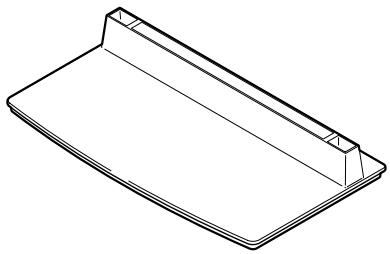
- Base cover x 1
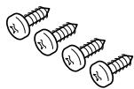
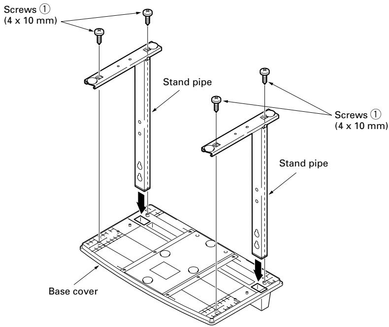
- Screws ① (4 × 10 ~mm) × 4

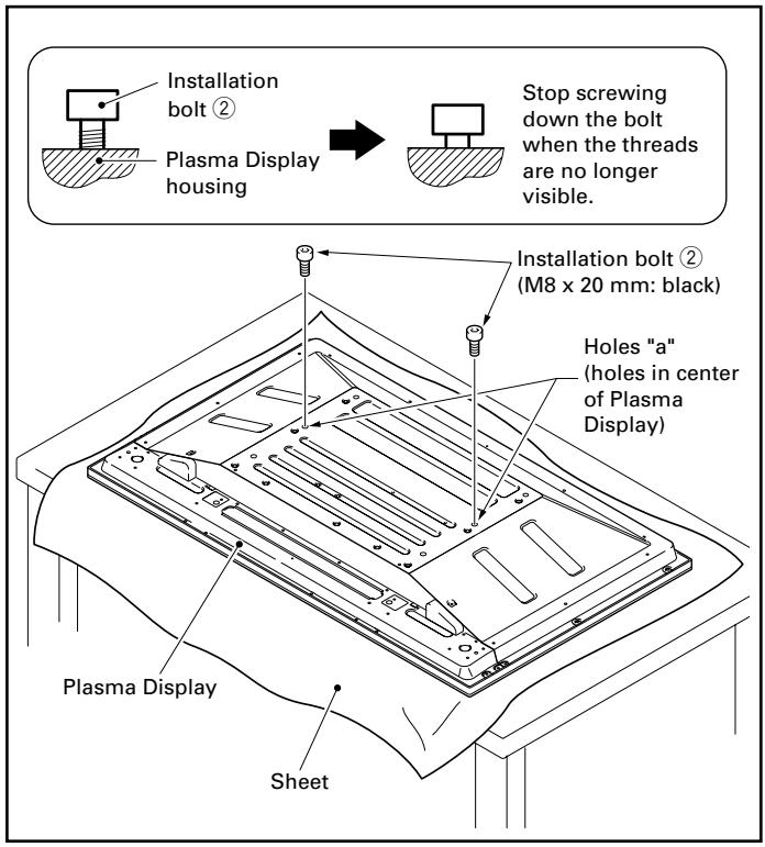
- Installation bolts ② (M8 x 20 mm: black) x 2
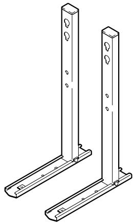
- Stand pipes (left and right, interchangeable) × 2

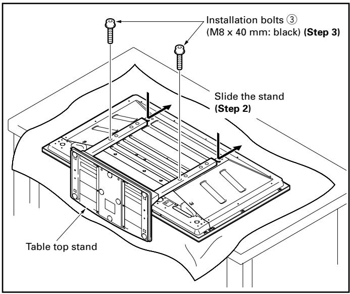
- Installation bolts ③ (M8 x 40 mm: black) x 2
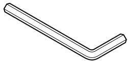
- Hexagonal wrench x 1 (Opposite side 6 mm for M8 use)

- Operating instructions (this document) x 1
Assembling the Stand
Assembly Procedure
1 Turn the base cover over so the underside is facing up.
2 Insert the stand pipes into the base cover.
3 Tighten the screws to stabilize the stand pipes.
Attaching the Plasma Display

Caution
The weight of a 50 inch Plasma Display is about 40kg (88 lbs), that of a 43 inch model is about 30kg (66 lbs), they have no depth, and are unstable. Therefore, at least two people must assemble and install them.
Note
- Insert the bolts in the holes vertically and do not tighten them with more force than necessary.
- Place a sheet or protective cover to protect the display from scratches or damage.
- Assemble only with the Plasma Display lying flat on a table or similar surface.
- Move the stand so that the stand screw holes and the nuts that connect the main display line up correctly.
1 With the Plasma Display lying flat, insert and secure the two Installation bolts ② (M8 x 20 mm: black) in the holes "a" located in center of the Plasma Display housing.
At this point, tighten these bolts ② only until the threads are no longer visible when viewed from the side (you will be unable to attach the display if the bolts are screwed in completely).
- Regarding the stand pipe screw holes when the stand is used as a desktop stand
Table: Stand pipe screw holes when the stand is used as a desktop stand
| Plasma Display model | Screw holes used with stand orientation |
| 43 inch display model | A, A' |
| 50 inch display model | B, B' |
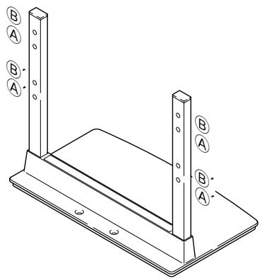
2 As shown in the above figure, hook the stand pipe holes (either pipe A or B) onto the screw heads of the installation bolts ②, then slide the stand upwards to the main Plasma Display until it engages the installation bolts ② (once put together with the display, the stand will slides no more than 19 mm (3/4 inch)).
3 Pass the installation bolts ③ (M8 x 40 mm: black) through the stand pipes and tighten the installation bolts firmly with the accessory hexagonal wrench (The holes should be used in the proper combinations, A- A' and B-B').
4 Tighten the installation bolts ② firmly with the accessory hexagonal wrench.
Installing the Product on a Rack etc.

Caution
When installing on a rack etc., hold the Plasma Display. If you hold the speakers, they may be damaged or twisted.
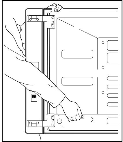
When holding the Plasma Display Erect:
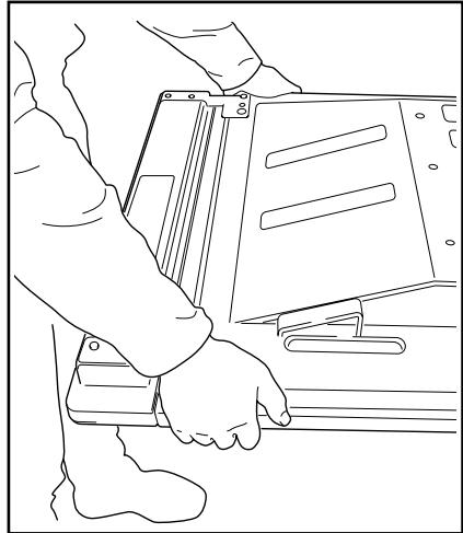
When laying down the Plasma Display:
Preventing Equipment from Falling Over
After installing the stand, be sure to take special care to ensure that the equipment will not fall over.
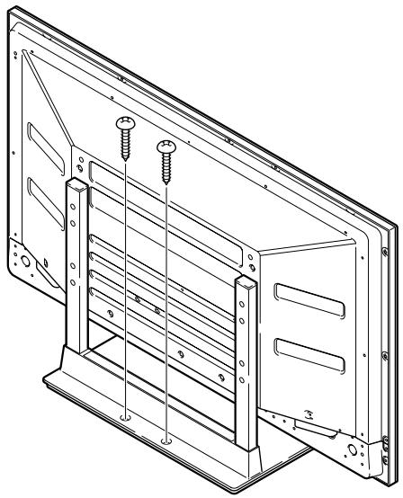
Stabilizing on table or floor
Stabilize the equipment as shown in the diagram using screws that are available on the market.
Note
To stabilize the equipment on a table or on the floor, use screws that have a nominal diameter of 6 mm (1/4 inch) and that are at least 20 mm (13/16 inch) long.
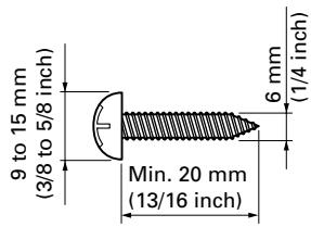
Position of table/floor screws
When stabilizing the stand to a table or the floor, use M6 with a length above 20mm (13/16 inch).
Unit: mm (inch)
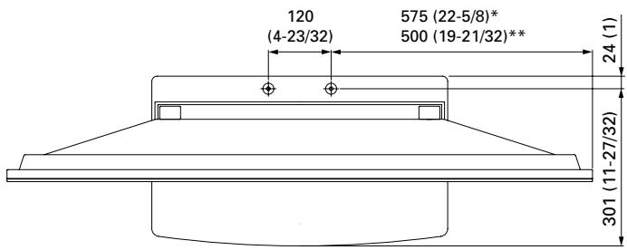
- : 50 inch display model
**: 43 inch display model
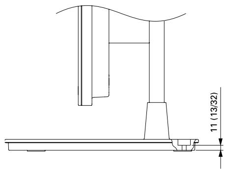
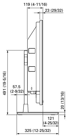
Dimension without speakers
Side View
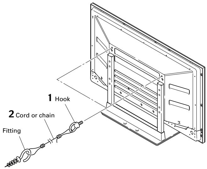
Using a wall for stabilization
1 Attaching falling prevention bolts (hooks) to the Plasma Display.
2 Using strong cords or chains to firmly stabilize it appropriately and firmly to a wall, pillar, or other sturdy element.
Perform this work in the same way on the left and right sides.
Note
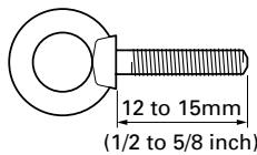
Use hooks, ropes, chains, and fittings that are available on the market.
Recommended hook: Nominal diameter M8 Length 12 to 15mm (1/2 to 5/8 inch)

Caution
- A table or an area of the floor with adequate strength should always be used to support the Plasma Display. Failure to do so could result in personal injury and physical damage.
- When installing the Plasma Display, please take the necessary safety measures to prevent it from falling or overturning in case of emergencies, such as earthquakes, or of accidents.
- If you do not take these precautions, the Plasma Display could fall down and cause injury.
- The screws, hooks, chains and other fittings that you use to secure the Plasma Display to prevent it from overturning will vary according to the composition and thickness of the surface to which it will be attached.
- Select the appropriate screws, hooks, chains and other fittings after first inspecting the surface carefully to determine its thickness and composition and after consulting a professional installer if necessary.
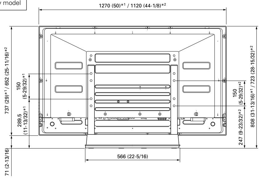
Specifications
External dimensions 566 (W) x 491 (H) x 325 (D) mm (22-5/16 (W) x 19-5/16 (H) x 12-25/32 (D) in.)
Weight 4.1 kg (9.0 lbs)
- The above specifications and exterior may be modified without prior notice to improve the product.
Without speakers
Unit: mm (inch)
^1 50 inch display model ^2 43 inch display model
When installing speakers on both sides of the Plasma Display
Unit: mm (inch)
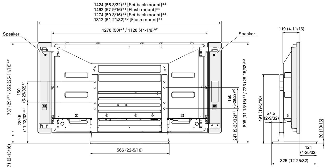
1 50 inch display model
2 43 inch display model
3 Set back mount: See the operating instructions for the speaker installation method.
4 Flush mount: See the operating instructions for the speaker installation method.
Published by Pioneer Corporation. Copyright © 2005 Pioneer Corporation. All rights reserved.
Publication de Pioneer Corporation.
© 2005 Pioneer Corporation
AFTER-SALES SERVICE FOR PIONEER PRODUCTS
Please contact the dealer or distributor from where you purchased the product for its after-sales service (including warranty conditions) or any other information. In case the necessary information is not available, please contact the Pioneer's subsidiaries (regional service headquarters) listed below:
PLEASE DO NOT SHIP YOUR PRODUCT TO THE COMPANIES at the addresses listed below for repair without advance contact, for these companies are not repair locations.
AMERICA
PIONEER ELECTRONICS (USA) INC.
CUSTOMER SUPPORT DIVISION
P.O. BOX 1760, LONG BEACH, CA 90801-1760, U.S.A.
CUSTOMER SERVICE HOTLINE : (800) 421-1404
EUROPE
PIONEER EUROPE NV
EUROPEAN SERVICE DIVISION
HAVEN 1087, KEETBERGLAAN 1, B-9120 MELSELE, BELGIUM
ASEAN
PIONEER ELECTRONICS ASIACENTRE PTE. LTD.
SERVICE DEPARTMENT
253, ALEXANDRA ROAD #04-01 SINGAPORE 159936
JAPAN AND OTHERS
PIONEER CORPORATION (HEAD OFFICE)
CUSTOMER SUPPORT CENTER
Printed on recycled paper
Published by Pioneer Corporation.
Copyright © 2005 Pioneer Corporation. All rights reserved.
PIONEER CORPORATION
4-1, Meguro 1-Chome, Meguro-ku, Tokyo 153-8654, Japan
PIONEER ELECTRONICS (USA) INC.
P.O. BOX 1540, Long Beach, California 90810-1540, U.S.A. TEL: (800) 421-1404
PIONEER ELECTRONICS OF CANADA, INC.
300 Allstate Parkway, Markham, Ontario L3R OP2, Canada TEL: 1-877-283-5901
PIONEER EUROPE NV
Haven 1087, Keetberlaan 1, B-9120 Melsele, Belgium TEL: 03/570.05.11
PIONEER ELECTRONICS ASIACENTRE PTE. LTD.
253 Alexandra Road, #04-01, Singapore 159936 TEL: 65-6472-7555
PIONEER ELECTRONICS AUSTRALIA PTY. LTD.
178-184 Boundary Road, Braeside, Victoria 3195, Australia, TEL: (03) 9586-6300
PIONEER ELECTRONICS DE MEXICO S.A. DE C.V.
Blvd.Manuel Avila Camacho 138 10 piso Col.Lomas de Chapultepec, Mexico,D.F. 11000 TEL: 55-9178-4270


- Installation
- IMPORTANT NOTICE
- Contents
- CAUTION
- Cautions
- Installation Location
- Assembling and Installation
- Checking the Standard Accessories
- Assembling the Stand
- Assembly Procedure
- Attaching the Plasma Display
- Note
- With the Plasma Display lying flat, insert and secure the two Installation bolts ② (M8 x 20 mm: black) in the holes "a" located in center of the Plasma Display housing.
- - Regarding the stand pipe screw holes when the stand is used as a desktop stand
- Installing the Product on a Rack etc.
- Preventing Equipment from Falling Over
- Stabilizing on table or floor
- Position of table/floor screws
- Using a wall for stabilization
- Specifications
- Without speakers
- When installing speakers on both sides of the Plasma Display
- AFTER-SALES SERVICE FOR PIONEER PRODUCTS
- AMERICA
- EUROPE
- ASEAN
- JAPAN AND OTHERS
- PIONEER CORPORATION
Brand : PIONEER
Model : PDK-TS10
Category : Audio accessory