
EY7540 - Power Tools PANASONIC - Free user manual and instructions
Find the device manual for free EY7540 PANASONIC in PDF.

| Product type | Cordless impact driver |
| Brand | PANASONIC |
| Model | EY7540 |
| Power supply | Li-ion battery 14.4 V DC, 3 Ah (EY9L40) |
| No-load speed (soft mode) | 0 - 1000 rpm |
| No-load speed (medium mode) | 0 - 1400 rpm |
| No-load speed (hard mode) | 0 - 2300 rpm |
| Impacts per minute (soft mode) | 0 - 2000 ipm |
| Impacts per minute (medium mode) | 0 - 2800 ipm |
| Impacts per minute (hard mode) | 0 - 3000 ipm |
| Maximum torque | 150 N·m |
| Overall length | 158 mm |
| Weight (with battery) | 1.45 kg |
| Chuck | Quick-release hex 6.35 mm (1/4 in) |
| LED light | Integrated, Class 1 |
| Power modes | 3 settings: soft, medium, hard |
| Safety | Overheat and over-discharge protection |
| Charger | Model EY0L80, charge time 35 min (usable) / 50 min (full) |
| Included accessories | Li-ion battery 3 Ah, charger, belt hook |
| Maintenance | Clean with a dry cloth; do not use water or solvent |
| General information | Indoor use; follow safety instructions |
Frequently Asked Questions - EY7540 PANASONIC
User questions about EY7540 PANASONIC
0 question about this device. Answer the ones you know or ask your own.
Ask a new question about this device
Download the instructions for your Power Tools in PDF format for free! Find your manual EY7540 - PANASONIC and take your electronic device back in hand. On this page are published all the documents necessary for the use of your device. EY7540 by PANASONIC.
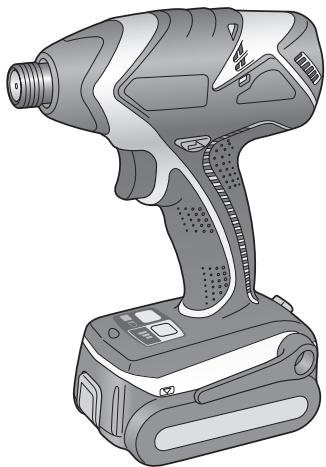
USER MANUAL EY7540 PANASONIC
Cordless Impact Driver
YdapHbI aKKyMnyTOpHbI wypynoBepT
UdapnH aKymyIaTOpHn uypynoBepT
Model No: EY7540
Before operating this unit, please read these instructions completely and save this manual for future use.
Peped 3KcIpyatauM daHHO yCTPOCTBA, noXaYnCTa, noNHOCTbIO pOHTNTe DAHHyIO IHCTpyKUIO IO COxPAHTE DAHHOE pyKOBOCTBO DIA IINOJIb3OBAMRA B6dyUJEM.
Ipeedeknnyatauicdo anaHoro npncptpo,6ydb naacka, noBhicto npouitraTe dany IHCTpykizio 3bepekeiTb daHHIONCIOHKI DRA BIKOPCCTAHN y MAHybTHbOMy.
Index/Index/Index/Indice/Index/Indeks/Index/Indeks/Hakemisto/ INdeKc/INdeKc
English: Page 5
Deutsch: 16
Français: Page 27
Italiano: 38
Read "the Safety Instructions" booklet and the following before using.
I. ADDITIONAL SAFETY RULES
1) Wear ear protectors when using the tool for extended periods.
2) Be aware that this tool is always in an operating condition, since it does not have to be plugged into an electrical outlet.
3) When screwing or driving into walls, floors, etc., "live" electrical wires may be encountered. DO NOT TOUCH THE HEX QUICK CHUCK OR ANY FRONT METAL PARTS OF THE TOOL! Hold the tool only by the plastic handle to prevent electric shock in case you screw or drive into a "live" wire.
4) Do NOT operate the Forward/Reverse lever when the main switch is on. The battery will discharge rapidly and damage to the unit may occur.
5) During charging, the charger may become slightly warm. This is normal.
Do NOT charge the battery for a long period.
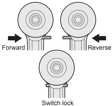
6) When storing or carrying the tool, set the Forward/Reverse lever to the center position (switch lock).
7) Do not strain the tool by holding the speed control trigger halfway (speed control mode) so that the motor stops.
| Symbol | Meaning |
| V | Volts |
| --- | Direct current |
| n0 | No load speed |
| .../min | Revolutions or reciprocations per minutes |
| Ah | Electrical capacity of battery pack |
| Read the operating instructions before use. | |
| For indoor use only. |
II. ASSEMBLY
Attaching or Removing Bit
NOTE:
-
When attaching or removing a bit, disconnect battery pack from tool or place the switch in the center position (switch lock).
-
Hold the collar of quick connect chuck and pull it out from the driver.
- Insert the bit into the chuck. Release the collar.
- The collar will return to its original position when it is released.
- Pull the bit to make sure it does not come out.
- To remove the bit, pull out the collar in the same way.
CAUTION:
- If the collar does not return to its original position or the bit comes out when pulled on, the bit has not been properly attached. Make sure the bit is properly attached before use.
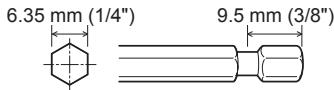
Use 6.35 mm (1/4") hexagonal bits.
To ensure proper securement of the bit, use only hexagonal bits with 9.5mm (3 / 8^ ) detent.
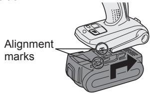
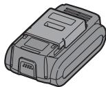
Attaching or Removing Battery Pack
- To connect the battery pack:
Line up the alignment marks and attach the battery pack.
- Slide the battery pack until it locks into position.
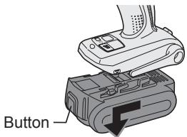
- To remove the battery pack: Push on the button from the front to release the battery pack.
III. OPERATION
[Main Body]
Switch and Forward/Reverse Lever Operation
CAUTION:
To prevent damage, do not operate Forward/Reverse lever until the bit comes to a complete stop.
Forward Rotation Switch Operation
- Push the lever for forward rotation.
- Depress the trigger switch slightly to start the tool slowly.
- The speed increases with the amount of depression of the trigger for efficient tightening of screws. The brake operates and the bit stops immediately when the trigger is released.
- After use, set the lever to its center position (switch lock).
Reverse Rotation Switch Operation
- Push the lever for reverse rotation. Check the direction of rotation before use.
- Depress the trigger switch slightly to start the tool slowly.
- After use, set the lever to its center position (switch lock).
CAUTION:
- To eliminate excessive temperature increase of the tool surface, do not operate the tool continuously using two or more battery packs. Tool needs cool off time before switching to another pack.
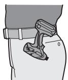
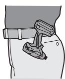
How to Use the Belt Hook
WARNING!
- Be sure to attach the belt hook securely to the main unit with the screw firmly fastened. When the belt hook is not firmly attached to the main unit, the hook may disconnect and the main unit may fall. This may result in an accident or injury.
Periodically check screw for tightness. If found to be loose, tighten firmly. - Be sure to attach the belt hook firmly and securely onto a waist belt or other belt. Pay attention that the unit does not slip off the belt. This may result in an accident or injury.
- When the main unit is held by the belt hook, avoid jumping or running with it. Doing so may cause the hook to slip and the main unit may fall. This may result in an accident or injury.
- When the belt hook is not used, be sure to return it to the storing position. The belt hook may catch on something. This may result in an accident or injury.
- When the unit is hooked onto the waist belt by the belt hook, do not attach driver bits to the unit. A sharp edge object, such as a drill bit, may cause injury or an accident.
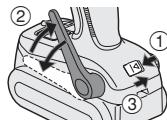
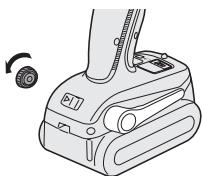
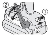
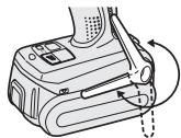
To Set the Belt Hook Angle Position
- Slide the belt hook lock lever ① and hold it to unlock the belt hook.
2.Pull the belt hook from storing position ② and set it.
-
Release the belt hook lock lever to lock the angle of belt hook.
4.Make sure the belt hook is firmly locked. Also make sure the belt hook is firmly locked into position ③ -
The belt hook cannot be locked in this position. Firmly lock it into position before use.
To return the belt hook to the storing position, Follow step 1. and 2. above, then lower the belt hook.
To secure the lock, follow 3 and 4 above.
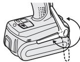
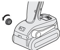
To Change the Belt Hook Location Side
The belt hook can be attached to either side of the unit.
- Set the belt hook at storing position.
- Loosen the screw turning it counterclockwise, using a flat metal or a flat blade screw driver.
- Take out the belt hook and insert into the other side of the slot on the main unit.
- Fasten the screw firmly, turning it clockwise.
The belt hook can be taken out from the main unit only when it is at storing position.
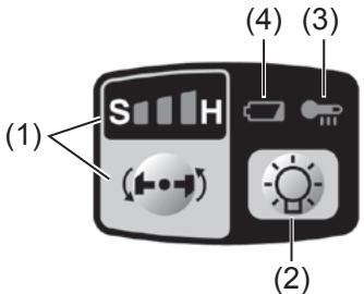
Control Panel
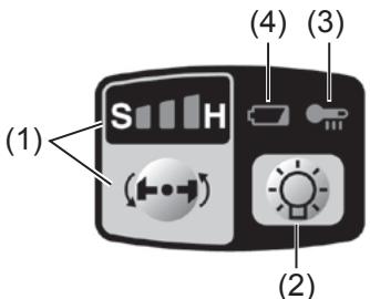
(1) Impact Power Mode Select
- Selecting the impact power among 3 modes (Soft, Medium, Hard).
Press the impact power mode button to set
it. The mode changes to hard, medium, or soft each time the button is pressed.
The driver is preset to "hard" impact mode setting when shipped from the manufacturer.
Recommended work guideline table
| Impact Power mode Display | Recommended Application |
| H 0-2300 r.p.m. and 0-3000 i.p.m. | Jobs requiring a high level of torque where there is no possibility of the screw breaking, its top shearing off, or the bit coming loose. (This setting provides maximum torque.) Suitable applications include: · Tightening M8 and larger bolts · Tightening long screws during interior finishing work |
| M 0-1400 r.p.m. and 0-2800 i.p.m. | Jobs requiring limited torque where there is a possibility of the screw breaking or its top shearing off. (This setting limits torque.) Suitable applications include: · Tightening bolts with smaller diameters (M6) · Tightening metalwork screws when installing fixtures |
| S 0-1000 r.p.m. and 0-2000 i.p.m. | Jobs requiring limited torque where there is a possibility of the screw breaking, its top shearing off, or the bit coming loose and damaging a finished exterior surface. (This setting limits torque.) Suitable applications include: · Tightening bolts smaller than M6 that may shear easily · Tightening screws into molded plastic · Installing gypsum wallboard |
- i.p.m. = Impact per minute.
(2) LED light
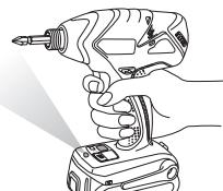
Pressing the button toggles the LED light on and off.
The light illuminates with very low current, and it does not adversely affect the
performance of the driver during use or its battery capacity.
CAUTION:
- The built-in LED light is designed to illuminate the small work area temporarily.
- Do not use it as a substitute for a regular flashlight, since it does not have enough brightness.
This product has the built-in LED lig
This product is classified into "Class 1 LED
Product" to EN 60825-1
Class 1 LED Product
Caution: DO NOT STARE INTO BEAM.
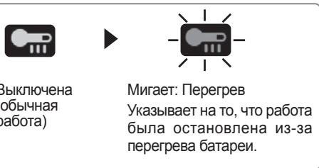
(3) Overheat warning lamp

Off (normal operation)


Flashing: Overheat
Indicates operation has been halted due to motor or battery overheating.
The overheating protection feature halts driver operation to protect the motor and battery pack in the event of overheating. The overheat warning lamp on the control panel flashes when this feature is active.
- If the overheating protection feature activates, allow the driver to cool thoroughly (at least 30 minutes). The driver is ready for use when the overheat warning lamp goes out.
- Avoid using the driver in a way that causes the overheating protection feature to activate repeatedly.
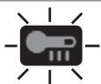
(4) Battery low warning lamp

Off (normal operation)

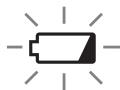
Flashing (No charge) Battery protection feature active
Excessive (complete) discharging of Li-ion batteries shortens their service life dramatically. The driver includes a battery protection feature designed to prevent excessive discharging of the battery pack.
- The battery protection feature activates immediately before the battery loses its charge, causing the battery low warning lamp to flash.
- If you notice the battery low warning lamp flashing, charge the battery pack immediately.
[Battery Pack]
For Appropriate Use of Battery Pack
Li-ion Battery Pack (EY9L40)
- For optimum battery life, store the Li-ion battery pack following use without charging it.
- The ambient temperature range is between 0^ (32^) and 40^ (104^) . If the battery pack is used when the battery temperature is below 0^ (32^) , the tool may fail to function properly.
- When battery pack is not in use, keep it away from other metal objects like: paper clips, coins, keys, nails, screws, or other small metal objects that can make a connection from one terminal to another.
Shorting the battery terminals together may cause sparks, burns or a fire.
- When operating the battery pack, make sure the work place is well ventilated.
- When the battery pack is removed from the main body of the tool, replace the battery pack cover immediately in order to prevent dust or dirt from contaminating the battery terminals and causing a short circuit.
Battery Pack Life
The rechargeable batteries have a limited life. If the operation time becomes extremely short after recharging, replace the battery pack with a new one.
Battery Recycling
ATTENTION:
For environmental protection and recycling of materials, be sure that it is disposed of at an officially assigned location, if there is one in your country.
[Battery Charger] Charging
Common Cautions for the Li-ion/Ni-MH/Ni-Cd Battery Pack
NOTE:
- When charging a cool battery pack (below 0^ ( 32^ ) in a warm place, leave the battery pack at the place and wait for more than one hour to warm up the battery to the level of the ambient temperature. Otherwise battery pack may not be fully charged.
Cool down the charger when charging more than two battery packs consecutively. - Do not insert your fingers into contact hole, when holding charger or any other occasions.
CAUTION:
To prevent the risk of fire or damage to the battery charger.
- Do not use power source from an engine generator.
- Do not cover vent holes on the charger and the battery pack.
- Unplug the charger when not in use.
Li-ion Battery Pack
NOTE:
Your battery pack is not fully charged at the time of purchase. Be sure to charge the battery before use.
Battery charger (EY0L80)
- Plug the charger into the AC outlet.
NOTE:
Sparks may be produced when the plug is inserted into the AC power supply, but this is not a problem in terms of safety.
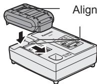
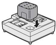
- Insert the battery pack firmly into the charger.
1 Line up the alignment marks and place the battery onto the dock on the charger.
2 Slide forward in the direction of the arrow.
- During charging, the charging lamp will be lit.
When charging is completed, an internal electronic switch will automatically be triggered to prevent overcharging.
- Charging will not start if the battery pack is warm (for example, immediately after heavy-duty operation).
The orange standby lamp will be flashing until the battery cools down.
Charging will then begin automatically.
- The charge lamp (green) will flash slowly once the battery is approximately 80% charged.
- When charging is completed, the charging lamp will start flashing quickly in green color.
- If the temperature of the battery pack is 0^ or less, charging takes longer to fully charge the battery pack than the standard charging time.
Even when the battery is fully charged, it will have approximately 50% of the power of a fully charged battery at normal operating temperature.
- If the power lamp does not light immediately after the charger is plugged in, or if after the standard charging time the charging lamp does not flash quickly in green, consult an authorized dealer.
- If a fully charged battery pack is inserted into the charger again, the charging lamp lights up. After several minutes, the charging lamp may flash quickly to indicate the charging is completed.
Ni-MH/Ni-Cd Battery Pack
NOTE:
When you charge the battery pack for the first time, or after prolonged storage, charge it for about 24 hours to bring the battery up to full capacity.
Battery charger (EY0L80)
- Plug the charger into the AC outlet.
NOTE:
Sparks may be produced when the plug is inserted into the AC power supply, but this is not a problem in terms of safety.
- Insert the battery pack firmly into the charger.
- During charging, the charging lamp will be lit.
When charging is completed, an internal electronic switch will automatically be triggered to prevent overcharging.
- Charging will not start if the battery pack is warm (for example, immediately after heavy-duty operation).
The orange standby lamp will be flashing until the battery cools down. Charging will then begin automatically.
-
When charging is completed, the charging lamp will start flashing quickly in green color.
-
If the charging lamp does not light immediately after the charger is plugged in, or if after the standard charging time the charging lamp does not flash quickly in green, consult an authorized dealer.
-
If a fully charged battery pack is inserted into the charger again, the charging lamp lights up. After several minutes, the charging lamp may flash quickly to indicate the charging is completed.
LAMP INDICATIONS

Green Lit
Charger is plugged into the AC outlet.
Ready to charge.

Green Flashing Quickly
Charging is completed. (Full charge.)

Green Flashing
Battery is approximately 80% charged (Usable charge. Li-ion only).

Green Lit
Now charging

Orange Lit
Battery pack is cool.
The battery pack is being charged slowly to reduce the load on the battery. (Li-ion only)

Orange Flashing
Battery pack is warm. Charging will begin when temperature of battery pack drops.
If the temperature of the battery pack is -10^ or less, the charging status lamp (orange) will also start flashing. Charging will begin when the temperature of the battery pack goes up (Li-ion only).

Charging Status Lamp
Left: green Right: orange will be displayed.
Both Orange and Green Flashing Quickly
Charging is not possible. Clogged with dust or malfunction of the battery pack.
Information on Disposal for Users of Waste Electrical & Electronic Equipment (Private Households)

This symbol on the products and/or accompanying documents means that used electrical and electronic products should not be mixed with general household waste.
For proper treatment,
recovery and recycling, please take these products to designated collection points, where they will be accepted on a free of charge basis. Alternatively, in some countries you may be able to return your products to your local retailer upon the purchase of an equivalent new product.
Disposing of this product correctly will help to save valuable resources and prevent any potential negative effects on human health and the environment which could otherwise arise from inappropriate waste handling. Please contact your local authority for further details of your nearest designated collection point.
Penalties may be applicable for incorrect disposal of this waste, in accordance with national legislation.
For Business Users in the European Union
If you wish to discard electrical and electronic equipment, please contact your dealer or supplier for further information.
Information on Disposal in Other Countries Outside the European Union
This symbol is only valid in the European Union.
If you wish to discard this product, please contact your local authorities or dealer and ask for the correct method of disposal.
IV. MAINTENANCE
Use only a dry, soft cloth for wiping the unit. Do not use a damp cloth, thinner, benzine, or other volatile solvents for cleaning.
V. TIGHTENING TORQUE
The power required for tightening a bolt will vary, according to bolt material and size, as well as the material being bolted. Choose the length of tightening time accordingly.
Reference values are provided below.
(They may vary according to tightening conditions.)
Factors Affecting Tightening Torque
The tightening torque is affected by a wide variety of factors including the followings. After tightening, always check the torque with a torque wrench.
1) Voltage
When the battery pack becomes nearly discharged, the voltage decreases and the tightening torque drops.
Bolt Tightening Conditions
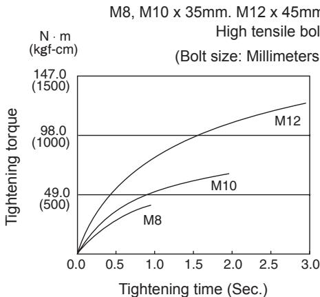
M10 x 35mm. M12, M14, M16 x 45mm
N·m Standard bolt (kgf-cm)
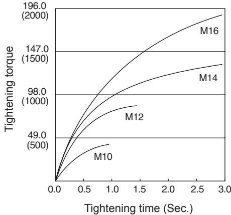
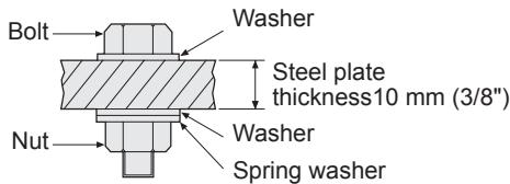
Tightening conditions
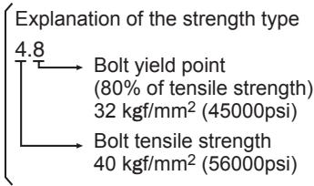
- The following bolts are used.
Standard bolts: Strength type 4.8
High tensile type 12.9
2) Tightening time
Longer tightening time results in increased tightening torque. Excessive tightening, however, adds no value and reduces the life of the tool.
3) Different bolt diameters
The size of the bolt diameter affects the tightening torque.
Generally, as the bolt diameter increases, tightening torque rises.
4) Tightening conditions
- Tightening torque will vary, even with the same bolt, according to grade, length, and torque coefficient (the fixed coefficient indicated by the manufacturer upon production).
- Tightening torque will vary, even with the same bolting material (e.g. steel), according to the surface finish.
- Torque is greatly reduced when the bolt and nut start turning together.
5) Socket play
Torque is lowered as the six-sided configuration of the socket of the wrong size is used to tighten a bolt.
6) Switch (Variable speed control trigger)
Torque is lowered if the unit is used with the switch not fully depressed.
7) Effect of Connecting Adaptor
The tightening torque will be lowered through the use of a universal joint or a connecting adaptor.
VI. ACCESSORIES
Use only bits suitable for size of chuck.
VII. APPENDIX
MAXIMUM RECOMMENDED CAPACITIES
| Model | EY7540 | |
| Screw driving | Wood screw | φ 3.5 - φ 9.5 mm (1/8" - 3/8") |
| Self-drilling screw | φ 3.5 - φ 6 mm (1/8" - 1/4") | |
| Bolt fastening | Standard bolt : M6 - M16 High tensile bolt : M6 - M12 | |
VIII. SPECIFICATIONS
MAIN UNIT
| Model | EY7540 | |
| Motor | 14.4 V DC | |
| No load speed | soft mode | 0 - 1000 /min (rpm) |
| medium mode | 0 - 1400 /min (rpm) | |
| hard mode | 0 - 2300 /min (rpm) | |
| Maximum torque | 150 N·m (1530 kgf-cm, 1330 in-lbs.) | |
| Impact per minute | soft mode | 0 - 2000 /min (ipm) |
| medium mode | 0 - 2800 /min (ipm) | |
| hard mode | 0 - 3000 /min (ipm) | |
| Overall length | 158 mm (6-1/4") | |
| Weight (with battery pack : EY9L40) | 1.45 kg (3.1 lbs) | |
BATTERY PACK
| Model | EY9L40 |
| Storage battery | Li-ion Battery |
| Battery voltage | 14.4 V DC (3.6 V x 4 cells) |
| Capacity | 3 Ah |
BATTERY CHARGER
| Model | EY0L80 |
| Rating | See the rating plate on the bottom of the charger. |
| Weight | 0.95 kg (2.1 lbs) |
[Li-ion battery pack]
| Charging time | 14.4 V | |
| 3 Ah | EY9L40 Usable: 35 min. | |
| Full: 50 min. |
[Ni-Cd/Ni-MH battery pack]
| Charging time | 7.2 V | 9.6 V | 12 V | 15.6 V | 18 V | 24 V | |
| 1.2 Ah | EY9065 | EY9080 | EY9001 | ||||
| EY9066 | EY9086 | ||||||
| 20 min. | |||||||
| 1.7 Ah | EY9180 | EY9101 | |||||
| EY9182 | EY9103 | ||||||
| 25 min. | |||||||
| 2 Ah | EY9168 | EY9188 | EY9106 | EY9136 | EY9116 | ||
| EY9107 | EY9117 | ||||||
| EY9108 | 60 min. | ||||||
| 30 min. | |||||||
| 3 Ah | EY9200 | EY9230 | EY9210 | ||||
| 45 min. | 90 min. | ||||||
| 3.5 Ah | EY9201 | EY9231 | EY9251 | ||||
| 55 min. | 65 min. | ||||||
NOTE: This chart may include models that are not available in your area. Please refer to the latest general catalogue.
ONLY FOR U. K.
IX. ELECTRICAL PLUG INFORMATION
FOR YOUR SAFETY PLEASE READ THE FOLLOWING TEXT CAREFULLY
This appliance is supplied with a moulded three pin mains plug for your safety and convenience.
A 5 amp fuse is fitted in this plug.
Should the fuse need to be replaced please ensure that the replacement fuse has a rating of 5 amp and that it is approved by ASTA or BSI to BS1362.
Check for the ASTA mark or the BSI mark on the body of the fuse.
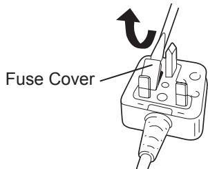
If the plug contains a removable fuse cover you must ensure that it is refitted when the fuse is replaced.
If you lose the fuse cover the plug must not be used until a replacement cover is obtained.
A replacement fuse cover can be purchased from your local Panasonic Dealer.
IF THE FITTED MOULDED PLUG IS UNSUITABLE FOR THE SOCKET OUTLET IN YOUR HOME THEN THE FUSE SHOULD BE REMOVED AND THE PLUG CUT OFF AND DISPOSED OF SAFELY.
THERE IS A DANGER OF SEVERE ELECTRICAL SHOCK IF THE CUT OFF PLUG IS INSERTED INTO ANY 13 AMP SOCKET.
If a new plug is to be fitted please observe the wiring code as shown below.
If in any doubt please consult a qualified electrician.
IMPORTANT:
The wires in this mains lead are coloured in accordance with the following code:
Blue: Neutral
Brown: Live
As the colours of the wire in the mains lead of this appliance may not correspond with the coloured markings identifying the terminals in your plug, proceed as follows.
The wire which is coloured BLUE must be connected to the terminal in the plug which is marked with the letter N or coloured BLACK.
The wire which is coloured BROWN must be connected to the terminal in the plug which is marked with the letter L or coloured RED.
Under no circumstances should either of these wires be connected to the earth terminal of the three pin plug, marked with the letter E or the Earth Symbol 1一
How to replace the fuse: Open the fuse compartment with a screwdriver and replace the fuse and fuse cover if it is removable.
This apparatus was produced to BS800.
Uit (normale Werking
(3) Varsellampe for overoppheting

Av (normalt arbeid)

VIII. TEKNISET TIEDOT
PÄALAITE
BHHMaHHe:HE CMOTPETb HAJIyU.
(3)П配电网电站站台站台站台站台站
ФункцязашитblOT neperpbebocta
HabInBaet paBoTy dpeNn DnA 3aunTb6BatapeHoro bCnyae ero neperpBea. KOrda FyHKnBkIouHeNaHeN ynpabEnnMiraet npedynpexKaiouaJaMaNoKaNeperpBea.
Bcnyae BkIoueHnA yHKun 3aunTbI OT neperpeBa daiTe dpEnO cHOBateJbHO OCTbIT (no MehSei Mepe B TeueHne 30 MInHyT). DpeNb BydET roTOBA K paBoTe NocJe BblKnUoyHn PpeDynpexKaIOSei JAMNOKNI.
- N36eraIte nCNoJIb3OBAHnA DpeIN TAKIM Obpa3OM, YTObI 3TO npINBOJnIO K HeODNOKpAthOMy BkLIuYeHNIO FyHKcUN 3aUHTbl OT neperpeBa.
Cpok cIyK6bl 6aTapeHOrO 6Joka
AkkymyIaTOPbIe 6batapeu IMeHOT orpaHnueHHbI cPOK cnyKbI. EcNI nOcne 3apJKnBpemf yHKUHOHPOBaHNr CTaHOBNTc4ype3MepHO KOpOTKIM, 3aMeHInTe 6batapeHbI BLOK Ha HOBbI.
Ytuln3aun6atapeu
BHIMAHHE:
B zeljx 3auntbI OKpykaHooe CpeblI yTNIN3aunM MaepnAIOB, yBeiNTecb, YTO OHa yTNIN3npOBaHa B OOFnAJIbHO npEHa3NaueHHOM MeTe, ecJN TaKOBleEcTB B BaWe CTpaHe.
[3apяДhoe ycTpoIcTBO] 3apяДka
ОьшиЕМерьИпeДОCTОРЖНСТДЯ ЛNTи-иOHнOrO/HnKeЛБ-MетаЛлогИдрNiDHorO/HnKeJIb-KaДмпeВOrO 6aTapeiHOrO 6bloka
ПРИМЕЧАНЕ:
-Пи зарядke xJOIoHOrO 6aTapeHoro 6Ioka (c Tempepatypoi HnKe 0^ (32^) B TeJIOM MeCTe, OCTaBbTe 6aTapeHbI bIOK B 3tOM MeCTe n IIOJoxdnte 6oJee OJHO raca, noka 6aTaper HaPeetcdo UpoBHr TEMpepatpybl OkpykaHoue cpebl. B npOTnbHom cnyuae, 6aTapeHbI 6Iok MoKET He 3apJNTcra NIOHocTbI.
- OxnaDnte 3apJHoe yCTpoIcTBO npn nocpeIOBATEbHOI 3apJdKe 6OJIee Yem DByx 6batapeINbIX 6NOKOB.
- He BCTABNJIte BaUN nAnbCbI B KONTAKTHbIe OTBepCTnI, KOrDa Bbl DePxNITe 3apJHoe yCTpOInCTBO, a TaKKe B Dpynx CnyaX.
BHIMAHNE:
Ipy npedotbpaueHn pncKa noxapa nnIOBpeKdHn3apnHOyCTpoNCTBa.
- He IncnoIb3yIe B KaueCTBe NCTOuHnKa nItaHa rRehepAtop DBratela.
- He 6noknyte BeHTNJrAIOHhIe OTBepCTNHa 3apJdHom yctpoiCtBe n 6aTapeHOM 6nOke.
- BbIKIIOHHe 3apJHoe yCTpoIcTBO n3 WTeNCeJIbHO pO3ETKn, eCNI OHO He IcNOJIb3yETc.
OCHOBHOE YCTPOINCTBO
IcO6 BCTaHOBHT Kyt NOBOpOTy NocHOrO KpHoka
1.3cyHbTe BaxiNb xfikcaii noIcHoro Kpoka ① i ytpmmyTe Ioro, 06 po36nokyBatn NOrCHN KpOK.
- Notaryt b noarchni Kpok 3 noJoxeHn Dnna 36epirahn ② iBCTaHObitb Noro nD notpi6Hm KYTOM.
- BldnycttB baxilb pfikcauii norchoro kpoka, 0o6 3aifikcybatn kyT noboporTy noarcho ro kpoka.
4.ПepekoHaITeCЯ,ло ПОЯСнй КрЮК MцHO 3a6nOKOBaHи.TakOxпepekoHaITeCЯ,ло ПОЯСнй КрЮК MцHO 3a6nOKOBaHиу nOJoxKeHHi ③
ПОЯСнй КРЮК He може 6ут n 3a6blOKOBaHn B DaHOMy nOJoxeHHI. Перд ВикориТаHHЯ MцHo 3a6blOKуЛte NOrO B NOTp6HOMy nOJoxeHHI.
Lio6 nobepHyTN NOrCHN KpOK B noIOJoxHnA DJIa 36epirAHn, dOtpmUyTEcB BUnceONncAHnx DiI nyHKTIb 1 ta 2, notim onycitb noRCHN KpOK.
Iio6 3a6nokyBatn φikcatop, DToPmUyTecb BUnSeONHcHx DiI nyHkTIB 3 Ta 4.
Lio6 3miHnTn CTOpOHy po3Mi- IeHHI NpOCHOrO KpOka
POnCHN KpIOK MOKe 6yTN pO3MiUeHN Ha 6yDb-RAkIN 3i CTOpIN 6nOKy.
1.BctaHObitnoCHN KpIOK B noIooKeHHn Dna 36epirAHH.
2. Ocna6Te rBnHT, o6eTahOu NiOro npOTn IOnHHNKOB0I cTpiJIKN, BnKOpNCtOBYUOni Dnla 0b0rMOHeTky a6oPiLOCKy BnKpyTKy.
3. BntraHtB noRCHN KpOK i BCtAte Noro B iHnii 6iK OTbpy Ha OCHOBOMy 6IoJI.
4.ⅢJIbHO 3aTЯHITb TBnHT,OBepTaIOU NOrO 3a TODINHHNKOBOHO CTpiIKOO.
IpoCHN KpIOK MOKe 6yTN BNTrHyTNI 3 OCHOBHOrO 6nOky JInSe JAKIo BOiH 3hAXoDITbCBy NIOJOKeHHI DnA 36epirAHn.
Панель урравлини
(1) Bn6ip peKIMy ydapy
- Ośnupačtbcra pěkúm ydapy 3 3 pěkúmíB (M'rkoro, cēpeɪnhóro i xkopctkoro).
Дя установки рекиму удару нашичы конь рекиму удару. Кхнор paу пи наши老人家 Кнорп реким удару 3мioэься на щорсткий, сердин做一个 M'який. Пп Biindравци 3 abody wypynobeert Bctan-HOBIOCTCB B "жорсткий" реким удару.
Ta6npu Bkazibok no po6oTi, zo pekomEnyIOTbcra
| Iидения рекиму notужноcti уdару | Викорисань, сiopekomeнданься |
| H 0 - 2300 ob/xb. ta 0 - 3000 ud/xb. | Роботи, яki notpe6byotb ВИСКОТО Г ribнг Кртунього МOMЕТУ Там, De Немаe ДIMOBIPHOCTI NGOMKII ЗБУРУ, ЗПЗАнНЯ NOLOВКII aбо PОЗИТУВАннЯ наcaДК. (Дана установки задзенье) MakIMMAлБИн KртуньнIH MOMENT). Пriчдаимп ВИКOPОСТANHМYС cЗAZHAЧЕH NIXКЕ: 3атягуньнг 6OЛТВ M8 тa бilingх 3атягуньнг DOВГХ шуруновп iizd chac oZdoБLOBДынHx mobiT |
| M 0 - 1400 ob/xb. ta 0 - 2800 ud/xb. | Роботи, яki notpe6byotb ОБмEKEGHERO кртуньгО MOMECHТУ Там, De E ДимOBIPHcTb ПОLOМКII шуруна abO 3PIa3HnA Иlorо rolOBКII. (Дана установки ОБмEKJCy KртуньнIH MOMENT). Пriчдаимп ВИКОPSТANHМY E NaHcTynHl: 3атягуньнг 6OЛТВ MeH脊О diametry (M6) 3атягуньнг ГИNTВ ДЯ Кріпеленny рpr BCTAHOBVIHNI ПИСТOCΥВан |

m = 311 ;
Danhi CmB0J diiChn TInbKn Ha TepuTopii EbponeiCbKoro Coio3y.
Ipn noTpe6i ytni3aui daHoro Bnpo6y 3BepHITc8 Do MicueBOro KepiBnHTBa a6o nnlepa oDo npabInbHOrO MeToy II 3diCHeHH.
IV. OBCJIyTOBYAHHЯ
Длгпротираннглрсстpoьвкорисовуte cyxmyяктуани. He binkopcstobyte dno Ounшень BOJORY TKAHNHy, po3piJxBya, 6eH3nabObI INJII JETyHi pO3HHNKn.
V. KPYTUNbHIM MOMENT 3ATJxKn
Cnla, 0 Heo6xHa nIa 3aT8KKn 60nTa MoKe BIdpi3HnTcB 3aIexKHoCTi BiD MaTepiany 60nTa i Noro pO3Mpy, a TAKoX BiD MaTepiany, 0 Ckpin7eTbC. BiNIOBIDHO ObnpaETbcr TaPBAJIcTb Yacy 3aT8KKn.
HnKyHe HabeDeHi 3NaueHnH, 0peKomeHnyOToBc.
(BoHMOKytb 3MiHOBaTnC8 B 3aJIeXHOCTi BiD yMOB 3aTRAKKN.)
(80%MexiMiuHoctiHa po3pmb)
32Kc/MM²(45000ФуHT/KB.Дю)
Meka milnocti Ha po3pmb
40 Krc/MM² (56000 ΦyHT/KB.ДийМ)
2)Yac3aTAAKK
BinbTpnbnnuac npn3bOntb Do 3pocTAnH KpyTnIbHOrO MOMeHTy 3aTJKN.
Haamipha 3aTgKa, Odnak, He noniunye kocti ickopohye ctpok ekcnnyatauii iHcTpymeHTy.
3) Pi3Ni diAmetpn 6oNTa
Pozmip Diamety BoNTa BnNbae Ha KpyTINbHIM MOMeHT 3aTAYKNI.
Irk npabnIO, 3i 3bInbJbeHnM diametpy 6oJIa 3pOCTa KpyTINbHm MOMeHT 3aTJKN.
4)YMOBN3aTAAKKN
KpytunbHn MOMENTaTJKKN bYe BliPir3HnTc HABIT DnI 60NTIB ODAHAKOBORO Knacy,doBxHHn I KOephiIeHTy KpytunbHoro MOMHTY (NoctiHN KoepoiieHT, oB BkayETbc BnpoBHKOM Ha npOdyKii).
KpytnbHm MOMENT 3aTJKK6yDe BIDpi3HrTcHABITb DnIg 6oNTiB 3 OndHO MATEpiaNy (HaPnKnaD, CTani), B 3aJeXHoCTi BID DOBOKn IOBepxHi.
KpyTulbHm MOMENT 3NaUHO 3NHXyETbcra, RaIIO 6oIT i raiKa nOuHaIOb oBepTaTcRa 10M.
5) 3a3op B natapoHi
KpyTnIbHm MOMENT 3HnxKyEtbc, JaKIO dIa3aTgKk6oNTa BVKOpNCTOByEcb NaTpOH weCTIrpaHHOfopMn HeBIDNOIBHOrO po3Mipy.
6) Bumikaq (pepeMkaq peyIIOBaHn 3MiHHoI WbNkoCTi)
Пи ВИКОпСТаHи ПИСТЮ 3 He NOВHICTH HATИСЧУТМ РЕМИКАЧЕМ КPyTuNJIbHIN MOMENT 3ΗΝΥΚΥΕΤБСЯ.
7) EfeKT 3'eHnyoUoro aanTepa
KpyTnIbHm MOMENT 3NHXyETbc, kAIO nIaC BnKOpNCtAHn yHIBepCaIbHoro po3'Emy a60 3'EDHyBaIbHoro aanTepy.
VI. ПИЛадя
BukopocTobuyte Iinye Hacaikn, 10 np iXoJyTB 3a po3mipom Do 3aTnckHoro NaTpoHy.
VII.ДОДАТOK
MAKcIMaJIbHI HABAHTAXEHHr, IIO PEKOMEHdYIOTbcra
[JIiTi-IOHHN 6aTapeHn 6JIOK]
[Hikeb-MetanoripnHn/Hikeb-KaMicBn 6aTapeHn 6Jok]
| Ча заряdkи | 7,2 B | 9,6 B | 12 B | 15,6 B | 18 B | 24 B | |
| 1,2Amné-тодINA | EY9065 | EY9080 | EY9001 | ||||
| EY9066 | EY9086 | ||||||
| 20xB. | |||||||
| 1,7Amné-тодINA | EY9180 | EY9101 | |||||
| EY9182 | EY9103 | ||||||
| 25xB. | |||||||
| 2Amné-тодINA | EY9168 | EY9188 | EY9106 | EY9136 | EY9116 | ||
| EY9107 | EY9117 | ||||||
| 30xB. | 60xB. | ||||||
| 3Amné-тодINA | EY9200 | EY9230 | EY9210 | ||||
| 45xB. | 90xB. | ||||||
| 3,5Amné-тодINA | EY9201 | EY9231 | EY9251 | ||||
| 55xB. | 65xB. | ||||||
Matsushita Electric Works, Ltd.
Osaka, Japan