
PLB114B - Flat Screen Mount Acme United - Free user manual and instructions
Find the device manual for free PLB114B Acme United in PDF.


| Product Type | Flat Panel Wall Mount |
| Brand | Acme United |
| Model | PLB114B |
| Compatible Screen Sizes | 26 to 55 inches |
| Maximum Weight Capacity | 50 lbs (22.7 kg) |
| VESA Compatibility | 100x100 mm to 400x400 mm |
| Materials | Steel, Plastic |
| Mounting Type | Wall mount with studs |
| Movement Type | Tilt, Swivel, Rotation |
| Tilt Range | +5° to -15° |
| Swivel Range | ±45° |
| Rotation Range | ±3° |
| Distance from Wall | 1.5 to 2.5 inches (38 to 64 mm) |
| Power Requirements | None (manual operation) |
| Maintenance & Cleaning | Wipe with dry cloth; avoid solvents |
| Safety Features | Secure to wall studs; weight limit must not be exceeded |
| Spare Parts & Repairability | Not user-serviceable; contact Acme United for replacements |
| General Information | Includes mounting hardware and instruction manual |
Frequently Asked Questions - PLB114B Acme United
User questions about PLB114B Acme United
0 question about this device. Answer the ones you know or ask your own.
Ask a new question about this device
Download the instructions for your Flat Screen Mount in PDF format for free! Find your manual PLB114B - Acme United and take your electronic device back in hand. On this page are published all the documents necessary for the use of your device. PLB114B by Acme United.
USER MANUAL PLB114B Acme United
Universal Wall Bracket

GB 4 Installation Instruction 88 Warranty card
LT 11 Montavimo instrukcija 89 Garantinis lapas
Unpacking instructions
- Carefully open the carton, remove contents and lay out on cardboard or other protective surface to avoid damage.
- Check package contents against the Supplied Parts List in the next page to assure that all components were received undamaged. Do not use damaged or defective parts.
- Carefully read all instructions before attempting installation.
Important safety information
Install and operate this device with care. Please read this instruction before beginning the installation, and carefully follow all instructions contained herein. Use proper safety equipment during installation.
Please call a qualified installation contractor for help if you:
- If you don't understand these directions or have any doubts about the safety of the installation.
- If you are uncertain about the nature of your wall, consult a qualified installation contractor.
Do not use this product for any purpose or in any configuration not explicitly specified in this instruction. We hereby disclaim any and all liability for injury or damage arising from incorrect assembly, incorrect mounting, or incorrect use of this product.
 WARNING WARNING | This TV mount must be securely attached to the vertical wall. If the mount is not properly installed it may fall, resulting in possible injury and/or damage. | ||
| Tools Required | • 5/32"(4mm) Drill Bit• Screwdriver | • 3/8"(10mm) Masonry Bit• Stud Finder | • Wrench or Socket Set• Carpenter's Level |
Note: The mounting components and hardware supplied in this package are not designed for installations to walls with steel studs or to cinder block walls. If the hardware you need for your installation is not included, please consult your local hardware store for proper mounting hardware for the application.
GB
Supplied parts list
 |  | 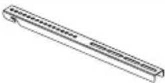 |
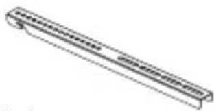
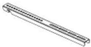
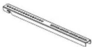
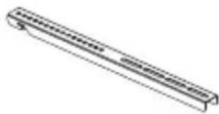
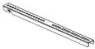
| (1)Wall Plate-a | (1)Left Monitor Bracket-b | (1)Right Monitor Bracket-c |
 |  |  |
| (4)M4x12 Bolt-d | (4)M5x12 Bolt-e | (4)M6x12 Bolt-f |
 |  |  |
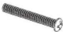
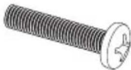
| (4)M4x30 Bolt-h | (4)M5x30 Bolt-i | (4)M6x35 Bolt-j |
 |  |  |
| (4)M4 Lock Washer-l | (4)M5 Lock Washer-m | (4)M6 Lock Washer-n |
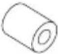 | 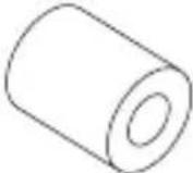 | 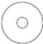 |
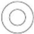
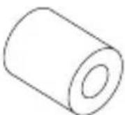
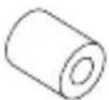
| (4)M4/M5 Space-p | (4)M6/M8 Space-q | (8)M4/M5 Washer-r |
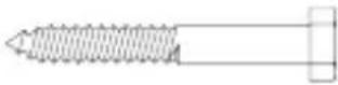 |  | 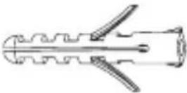 |
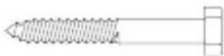
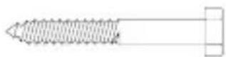
| (3)Lag Bolt-t | (3)Lag Bolt Washer-u | (3)Concrete Anchor-v |
Mounting the monitor brackets to a TV with flat back
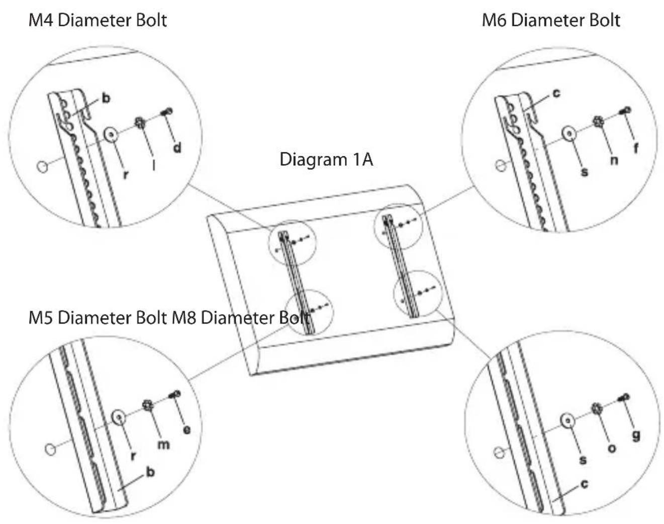
First of all, make sure the diameter of the Bolt (d,e,f,g) your TV requires. Once you have determined the correct diameter, please see the relative diagram as below. You will thread the Bolt into the TV using the correct Lock Washer (l,m,n,o) and Washer (r,s). Please make sure the Monitor Brackets (b,c) are vertically centered and level with each other.
GB
Mounting the monitor brackets to a TV with curved back
First of all, make sure the diameter of the Bolt (h,i,j,k) your TV requires. Once you have determined the correct diameter, please see the relative diagram as below. You will thread the Bolt into the TV using the correct Lock Washer (l,m,n,o), Washer(r,s) and spacer (p,q). For the M4 or M5 diameter bolt, you will need another M4/M5 Washer between the Monitor Bracket and the Spacer. Please make sure the Monitor Brackets are vertically centered and level with each other.

Mounting the wall plate to the wall
Brick, Solid Concrete and Concrete Block mounting:
Use the Wall Plate(a) as a template to mark 3 hole locations on the wall. Make sure these holes are level. Pre-Drill these holes with a 3/8"(10mm) masonry bit to at least 2.4"(60mm) in depth. Insert a Concrete Anchor(v) into each of these holes.
Make sure the anchor is seated completely flush with the concrete surface even if there is a layer of drywall or other material in front. Attach the Wall Plate to the wall using 3pcs Lag Bolts(t) and 3pcs Lag Bolt Washers(u), shown in Diagram 2A.
Wood Stud mounting:
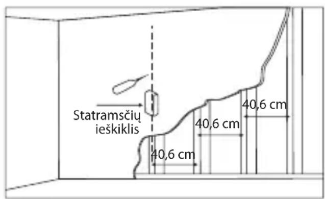
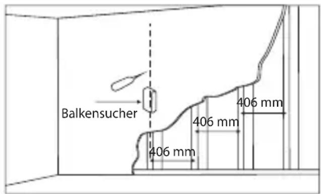
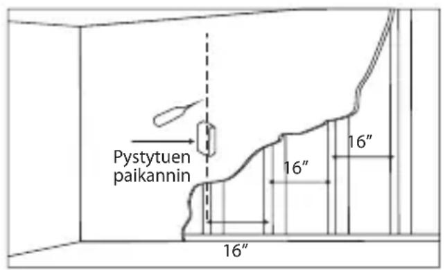
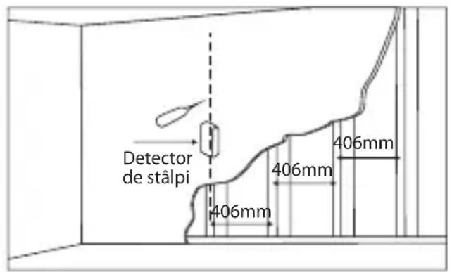
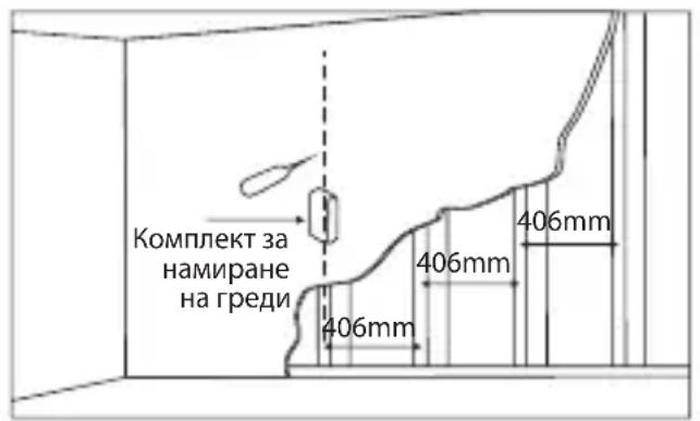
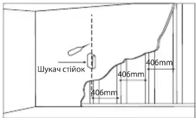
The Wall Plate (a) must be mounted to two wood studs at least 16"(406mm) apart. Use a stud finder to locate two adjacent studs. It is a good idea to verify where the studs are located with an awl or thin nail shown in Diagram 2B. Pre-drill a 2.4"(60mm) deep hole at the desired height in each stud using a 5/32"(4mm) drill bit. Make sure these holes are in the center area of the studs and level with each other. Attach the Wall Plate to the wall using the 2pcs Lag Bolts(t) and 2pcs Lag Bolt Washers(u).

GB
Attaching monitor to wall plate
Warning: Some TVs may require two people to lift! We are not responsible for personal injury or product damage.
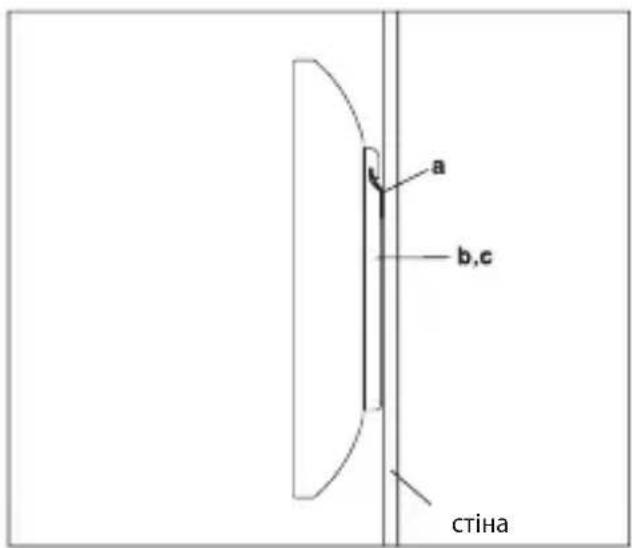
First hook the Monitor Brackets(b,c) over the top of the wall Plate(a), then let the bottom of the Monitor Brackets rotate to the wall as shown in the Diagram 3A. The finishing looking as shown in the Diagram 3B.
Thanks for choosing our products, enjoy the using.
(4) M 4 x 30 varžtas – h (4) M 5 x 30 varžtas – i (4) M 6 x 35 varžtas – j (4) M 8 x 40 varžtas – k
(1) Monitora kreisās puses kronšteins – b
(4) 8 mm skrūves x 40 - k

(4) 4 mm
kontrpaplāksne – I

(4) 5 mm
kontrpaplāksne – m

(4) 6 mm
kontrpaplāksne – n

(4) 8 mm
kontrpaplåksne - o
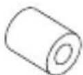
(4) 4 mm/5 mm starplika - p
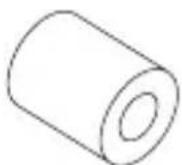
(4) 6 mm/8 mm starplika - q
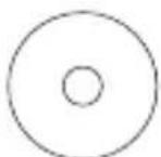
(8) 4 mm/5 mm paplāksne – r

(4) 6 mm/8 mm
paplāksne - s
(1) Seinaplaat-a (1) Vasakpoolne
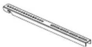
monitori tugi-b
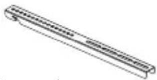
(1) Parempoolne monitori tugi--c


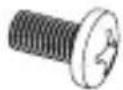
(4)M4x12 polt-d (4) M5x12 polt-e (4) M6x12 polt-f (4) M8x16 polt-g

(4) M4x30 polt-h (4) M5x30 polt-l (4) M6x35 polt-j
t-l (4) M6x35 polt-j

(4) M8x40 polt-k

(4) M4 lukustusseib-I

(4) M5 lukustusseib -m
(4) M4/M5 vahedetail-p (4) M6/M8 vahedetail -q (8) M4/M5 seib-r (4) M6/M8 seib-s
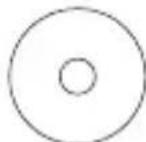
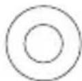
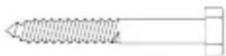
(3) Keermega polt-t (3) Keermega poldi seib-u (3) Tüübel -v

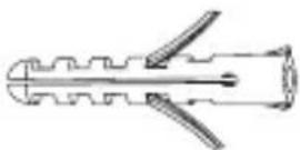
EE
Monitori kinnitusdetailide paigaldamine lameda tagaküljega teleritele

(4) Bolzen M4x30-h (4) Bolzen M5x30-l (4) Bolzen M6x35-j (4) Bolzen M8x40-k



(4) M4x30 pultti-h (4) M5x30 pultti-l (4) M6x35 pultti-j (4) M8x40 pultti-k



FI
RO
(4)Болт М4x30 - h (4)Болт М5x30 - i (4)Болт М6x35 - j (4)Болт М8x40 - k


(4)Стопорна шайба М4 - I
(4)Стопорна шайба M5 -m
(4)Стопорна шайба М6 – n
(4)Стопорна шайба M8 - o


(4)Вставка M4/M5 – p (4)Вставка M6/M8 – q (8)Шайба M4/M5 – r (4) Шайба M6/M8 - s

| Product Product model | |
| Product purchase date Seller name, address | |
| Failures (date, description, position of the person who accepts the product, first name, last name and signature) | |
1. Warranty period
Warranty enters into force starting with the day when the buyer acquires the product from the seller. Warranty period is indicated on the package of the product.
2. Warranty conditions
The warranty is valid only by providing an original document of the product acquisition and this warranty sheet, which includes name of the product model, product purchase date, name and address of the seller.
If it is noticed during the warranty period that the product has faults and these faults where not caused by any of the reasons when the warranty is not applied as indicated in the paragraphs below, manufacturer undertakes to replace the product.
The warranty is not applied to regular testing, maintenance and repair or replacement of the parts which are worn out naturally.
The warranty is not applied if damage or failures occurred due to the following reasons:
- Inappropriate installation of the product, inappropriate usage and/or open product without following the manual, technical requirements and safety standards as provided by the manufacturer, and additionally, inappropriate warehousing, falling from heights as well as hard strikes.
• Corrosion, mud, water and sand. - Repair works, modifications or cleaning, which were performed by a authorised by the manufacturer.
- Usage of the spare parts, software or consumptive materials which do not apply to the product.
- Accidents or events or any other reasons which do not depend on the manufacturer, which includes lightning, water, fire, magnetic field and inappropriate ventilation.
- If the product does not meet standards and specifications of a particular which it was not bought. Any attempt to adjust the product in order to meet technical and safety requirements such as those in the other countries withdraws all the rights to the warranty service.
If no failures are detected in the product, all the expenses in relation to the service are covered by the buyer.
Garantinis lapas www.acme.eu/warranty


- UNIVERSAL WALL BRACKET
- UNPACKING INSTRUCTIONS
- IMPORTANT SAFETY INFORMATION
- PLEASE CALL A QUALIFIED INSTALLATION CONTRACTOR FOR HELP IF YOU
- GB
- SUPPLIED PARTS LIST
- MOUNTING THE MONITOR BRACKETS TO A TV WITH FLAT BACK
- MOUNTING THE MONITOR BRACKETS TO A TV WITH CURVED BACK
- MOUNTING THE WALL PLATE TO THE WALL
- BRICK, SOLID CONCRETE AND CONCRETE BLOCK MOUNTING
- WOOD STUD MOUNTING
- ATTACHING MONITOR TO WALL PLATE
- EE
- MONITORI KINNITUSDETAILIDE PAIGALDAMINE LAMEDA TAGAKÜLJEGA TELERITELE
- FI
- RO
- WARRANTY PERIOD
- WARRANTY CONDITIONS
- GARANTINIS LAPAS WWW.ACME.EU/WARRANTY
Brand : Acme United
Model : PLB114B
Category : Flat Screen Mount