USER MANUAL SKR301 MAKITA
1.1 Description
1.2 Technical Specifications
1.3 Overview
1.4 Overview of keypad
- Operating instructions 5
2.1 Auto/Man key
2.2 Tilt key
2.3 Horizontal setup
2.4 Vertical setup
2.5 Squaring
2.6 Rotation speed
2.7 Using the chalk line
2.8 Using the scanning
2.9 Manual slope
3.0 Power
- Checking and adjusting your SKR301 9
3.1 Horizontal checking and calibration
3.2 Vertical checking and calibration
- Care and handling 12
5.Warranty 13
- Accessories 13
6.1 Detector
6.2 Remote control
6.3 Mountains
6.4 Other Accessories
Although the SKR301 is very simple to use, we recommend that you read this manual before operating the laser.
1.1 Description
The SKR301 is an automatic visible laser that can be used for leveling, vertical alignment, plumbing and squaring. Applications include installing suspended ceilings, technical flooring, partitions and a variety of outdoor alignment work.
The SKR301 laser has these advanced features :
Automatic self-leveling in both horizontal and vertical modes
- Choice of beams: rotating plane, scanning, chalk line, single point or constant squaring
- Easy electronic calibration
- Square shot that's left/right adjustable
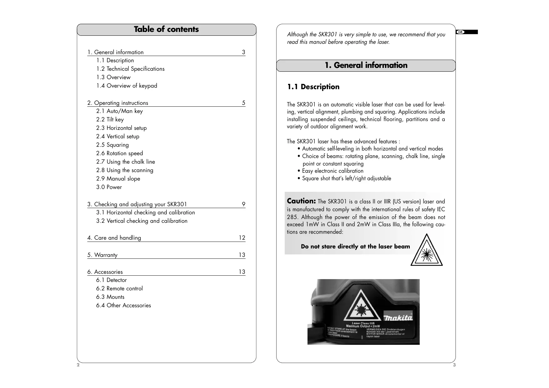
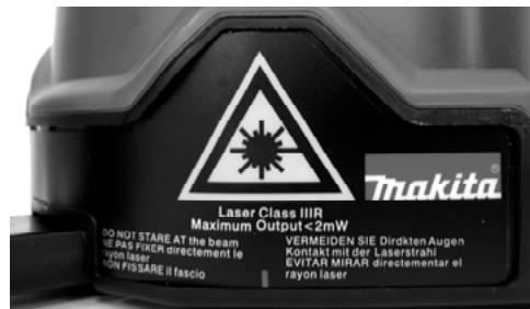
Caution: The SKR301 is a class II or IIIR (US version) laser and is manufactured to comply with the international rules of safety IEC 285. Although the power of the emission of the beam does not exceed 1mW in Class II and 2mW in Class IIIa, the following cautions are recommended:
Do not stare directly at the laser beam
1.2 Technical Specifications
| Recommended use (diameter) | 1,000 ft. (300m) with detector |
| Leveling accuracy | 0.010 % (+/- 1/8" at 100 feet +/-10 mm at 100 m) |
| Leveling range | + / - 8 % |
| Scanning angle | From 3° to 34° |
| Laser diode | 635 nm maximum European version: 1mW, Class II US version: 2mW, class IIIR |
| Power | 2 alkaline batteries (LR20 or D) or rechargeable batteries |
| Charging time | 15 hours |
| Battery life | 40 hours with rechargeable batteries 160 hours with alkaline batteries |
| Size | 6" × 6 1/2" × 6 3/4" (15 x 16 x 17 cm) 3 lbs (1.3 kg) |
| Rotation speed | 0-90-150-300-450-600 rpm |
| Weatherproof | Rain and dustproof (IP65) |
1.3 Overview
- Rotating head
- Plumb or square laser beam aperture
- Laser beam aperture
- Laser chalk line aperture
- Arrow
- 90^ index mark (one of four)
- Retractable foot for vertical setup
- Adjustable feet for vertical setup
- Batteries
- Jack for battery charger
11.5/8-11 mount
- Top cover
1.4 Overview of keypad
- Laser rotation control to the left + speed control Save calibration data
- Laser rotation control to the right + speed control Change calibration Axis
- Moving the square shot to the right / Move beam down
- Moving the square shot to the left / Move beam up
- Capture window for remote control
- Manual mode LED / Z Axis calibration indicator
- Manual / Automatic
- H.I Alert light / Y Axis calibration indicator
- H.I Alert (Tilt)
- Battery low light / X Axis calibration indicator
- On/Off
Italics correspond to indication and keys used in calibration mode.
2. How to use your SKR301 laser
An overview of laser and keypad functions can be found in the inside front cover.
The laser does a self-test when turned on. The beam blinks while the laser is self-leveling. After it has leveled, the head will start to rotate.
2.1 Auto/Man key (20)
Default mode when laser is switched on
- Man: Manual use
The SKR301 laser is always in the automatic self-leveling mode (auto) when turned on. Once the instrument has self-leveled, the laser head will start rotating.
You can choose to have constant rotation by using the manual mode. This way, the beam will rotate even if the instrument is not leveled (necessary when working on inclined planes).
For safety, a red light will blink above the Auto/Manual button to advise the user that the laser is in manual mode.
2.2 Tilt key (22)
Tilt : H.I.-Alert mode. Will work only when selected. The Tilt function is also known as the H.I. (height of instrument) Alert. This feature stops the laser automatically if the laser is jarred or moved, preventing inaccurate readings. Use this feature only in automatic mode, not in manual.
Push the Tilt key (22) after turning the instrument on. The H.I. Alert feature is available 30 seconds after the instrument has self-leveled. The red light above the Tilt key will blink when operating in this mode. If the laser is disturbed, the head will stop rotating and the red light will be on continuously. Turn the laser off, wait 5 seconds, and turn it on again (check that the beam is at its original reference).
2.3 Horizontal setup
- The SKR301 laser can be used directly on the ground, on a wall mount or on a standard tripod (5/8 - 11).
- Press the On/Off key (24) to switch the laser on. It will start its automatic leveling.
- To select the Manual mode, press key (20).
- To select the H.I.-Alert mode, press key (22). This feature is available 30 seconds after the laser has leveled itself.
- If you wish to move the laser beam to a specific point, briefly press key (14) or (15).
- To adjust the rotation speed, press key (14) or (15) continuously according to the direction you wish. To stop the rotation, press once on the opposite key.
- To turn the laser off, press key (24).
2.4 Vertical setup
No accessories are needed for this position. The SKR301 can be used directly on the ground. However, it can be used on a mount for a better setup.
- Flip up the retractable foot (7). Place the instrument in vertical position, resting on this foot. Use the adjustable feet (8) to rough level the laser.
- Turn the instrument on. Once the instrument is leveled, the head will start rotating.
2.5 Squaring
-
Put the laser on the ground and repeat steps 1 and 2 for vertical use.
-
Stop the head rotation by pressing key (14) or (15).
-
To position the rotating vertical plane perpendicular to a reference line:
-
Align the arrow (5) located below the beam aperture with the index (6) located above the retractable foot (there is also an index mark on the foot).
- Move the laser so that the beam is over the reference point on the ground, keeping the arrow and index aligned.
- Align the beam projecting from the top of the head to your second reference point with key (16) or (17) on the laser or with the detector or remote control. (This beam is 90^ , or square, to the other vertical plane beam).
- Start rotating the head using keys (14) or (15) to change speed or use the chalk line.
It is important to check while you're using the laser that it has not been moved and that your setting is still accurate.
2.6 Rotation speed
Your laser is equipped with a visible laser diode. It may be necessary to adjust the rotation speed according to the ambient light conditions using keys (14) and (15).
The laser beam is more visible in slow motion. It is possible to stop the rotation and point the beam manually to view the beam over long distances.
2.7 Using the chalk line
Ideal for viewing at short distances. To use the laser line feature, hold the head and rotate the top cover (12) so that the beam comes out of the laser line aperture (4). This will give a precise and stable laser line for working directly on your reference plane. You can move the line by rotating the head manually or by using the remote control.
The LDR180 detector will not work with the chalk line feature.
2.8 Using the scanning mode
Allows you to see the beam easier when the laser is further away. To use the scanning feature, turn the laser on. The laser should be in 'point' mode.
If it is in chalk line, hold the head and rotate the top cover (12) so that the beam comes out of the beam aperture (3). To put laser on scan mode, use keypad, detector, or remote.
- To scan, simultaneously press (14) and (17). The beam will blink until it has self-leveled, and then will start scanning.
- Use (14) or (15) to aim the scan.
- Use the bottom two keys to adjust the scanning length. Use (17) to increase and (18) to decrease (3^ to 34^) .
- To turn the scanning off, simultaneously press (14) and (17) again. The square shot cannot be moved left or right when scanning; laser must be in point or chalk line mode.
2.9 Manual slope
- After turning the laser on and allowing it to self-level, press the Auto/Man key (20). The LED next to it (19) will blink, indicating you are in manual mode and you can set slope in the X axis. The head will start rotating.
- Press (17) to set a positive slope in X and press (16) to set a negative slope.
- To switch to the Y axis, press the Tilt key (22). Both LEDs (19) and (21) will blink, indicating that you are in manual mode and that you can set slope in Y axis.
- Press (17) to set a positive slope in Y and (16) to set a negative slope.
3.0 Power
3.0.1 Installing alkaline batteries
- To install alkaline batteries in your SKR301 laser, unscrew the battery cap located at the bottom of the instrument.
- Remove the battery pack.
- Insert two alkaline batteries (D or LR20) in the pack, matching the polarity (^ + ^ or - - ^ ) as indicated at the bottom of the pack.
- Put the battery back into its place and tighten the screw. Your A 410 is ready for use.
To replace batteries
- When battery power is low, the laser head will stop rotating, and the low battery light (23) will come on.
- Replace both batteries at the same time.
3.0.2 Using rechargeable batteries
First-time use
If your SKR301 is equipped with rechargeable battery, you must recharge it for 15 hours before first use.
- Insert the recharger jack plug into the jack located on the battery pack (10).
- Plug the charger into an electrical outlet (110 volts or 220 volts, depending on charger and country).
- Charge for 15 hours.

Always recycle batteries

Do not discard batteries into garbage can or the like
Later recharges
The SKR301 can be charged while working. If electricity is available on the job site, simply plug in the charger and keep on working. You can also remove the battery pack to charge it, and replace with the alkaline battery compartment to keep on working.
For optimum life of the battery, it is recommended to only charge the battery after it has been fully discharged.
To ensure battery life, do not charge over 20 hours. The battery and the charger can be damaged if damp. Always store and charge your instrument in a dry and covered place.
3. Checking and adjusting your SKR301
THIS CHAPTER IS VERY IMPORTANT: Here are a few simple instructions to check your SKR301 for calibration.
Remember that the laser is a precision instrument and that it is important that you keep it calibrated and in proper condition. The accuracy of your work is completely your responsibility and you should regularly check your instrument especially prior to important jobs. Before any checking on calibration ensure laser is in point mode when rotation stopped. Directions follow for checking each axis for calibration. If the laser needs to be calibrated, follow the instructions or take it to a service centre.
3.1 Horizontal checking and calibration (X and Y axis)
3.1.1 Horizontal checking
Y axis
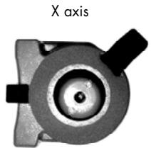
Z axis
-
Place the laser on a flat surface 50 or 100 ft. (30m) from a wall. Position it so that the X 1 is facing the wall.
-
Turn the laser on. After it's level, stop the rotation so that the beam is a point.
-
Mark the location of the beam.
-
Rotate the laser 180^ . After 90 seconds, mark the location of the beam near the first mark.
-
Both measurements must be at the same place. At 100 ft., the marks should be no more than 18 apart. At 50 ft., the marks should be no more than 116 apart. (At 30 meters, no more than 6 mm apart). This is +/- 0.010% leveling accuracy.
-
If the marks are close enough, X axis is within calibration. The second axis (Y) must then be checked (see Step 7). If the marks are not close enough, the x axis needs to be re-calibrated (see instructions below).
-
To check the y axis, turn the laser 90^ from Step 4 so that Y 1 is facing the wall. Repeat the same steps: mark the Y beam, rotate 180^ , and mark again. If the marks are more than 1/8'' apart at 100 ft., Y axis should be re-calibrated.
3.1.2 Horizontal calibration
The laser must be calibrated to bring the beam to the centre of the two marks (Steps 3-4 in 3.1.1). The calibration is easily done using the laser keypad, remote control, or detector.
X axis calibration
- Turn the laser off before switching to calibration mode. Simultaneously press two laser keys, On/Off and auto/man.
- After a few seconds, release On/Off key.
- The X LED indicator (23) will blink, then the y LED (21). Release the auto/man key.
- The X LED (23) will blink rapidly, indicating the laser is ready to
be calibrated in the X axis. If you have not moved the laser, use the X marks made in Steps 3 and 4 of 3.1.1 (Horizontal Checking).
- Mark the spot that's halfway between the two marks.
- With X 2 facing the marks, bring the laser beam up or down to the centre mark by using (16) or (17) on the laser keypad or (2) or (3) on the detector or remote.
- Next, check Y axis against centre mark. Tu m the laser 90^ so that Y 2 faces the wall. If the beam is not on the centre mark, calibrate Y. If Y is OK, see «Saving calibration» below.
Y axis calibration
- To change to Y axis calibration, press (15) on the laser or (4) on detector or remote.
The Y LED will blink rapidly, indicating that the laser is ready to be calibrated in the axis.
- If you have not moved the laser, use the centre mark from above. Bring the laser beam up or down to that centre spot by using (16) or (17) on the laser keypad or (2) or (3) on the detector ro remote.
Saving the calibration
The laser is now calibrated in the X and Y axis. Press (14) on keypad or (5) on detector or remote to save the calibration data. If you don't wish to save the calibration, press the On/Off key (24) on the laser.
3.2 Vertical checking and calibration (Z axis)
3.2.1 Vertical checking
- Place laser in vertical mode, on a flat surface about 10 ft. away from a plumb line (plumb bob hanging on a string, at least 8 ft. high). If you need to calibrate, beam will be easier to see in a darkened room.
- Use the adjustable feet to rough level the laser.
- Turn the laser on. Stop the rotation so that the beam is a point.
- Hold the laser head and move the beam up and down the entire length of the plumb line by hand. If the beam is slanted, and not vertical like the plumb line, the z axis needs calibration.
3.2.2 Vertical calibration
-
Turn the laser off before switching to calibration mode. Simultaneously press On/Off and Auto/Man.
-
After a few seconds, release On/Off key.
- The X LED indicator (23) will blink, then the Y LED (21). Release the Auto/Man key.
- The Z LED (19) will blink rapidly, indicating laser is ready to be calibrated in Z axis.
- Move the beam until it's vertical and parallel to the plumb line using (16) or (17) on the laser or (2) or (3) on the detector or remote. Move the laser slightly so that the beam is over the plumb line for the final check.
Saving the calibration
The laser is now calibrated in Z axis. Press (14) on laser or (5) on detector or remote to save the calibration data. If you don't wish to save the calibration, press the On/Off Key on the laser.
4. Care and handling
CAUTION: Use of controls or adjustments or performance of procedures other than those specified herein may result in hazardous radiation exposure.
- The SKR301 is a precision instrument which must be handled with care. Avoid shock and vibrations. Always store and transport the laser and accessories in the carrying case.
- Although weather resistant, you must always keep your laser and its accessories dry and clean after using. This will increase the battery life.
- Do not store your laser at temperatures below -4^ (-20^) or above 176^ (80^) , because the electronic components could be damaged.
- Do not store your instrument in its case if the instrument or the case are wet, to avoid water condensation inside the instrument.
- To maintain the precision of your laser, check and adjust it regularly.
- Keep the lenses of the apertures (2) and (3) clean. Use a soft cloth and glass cleaner.
- It is recommended to regularly charge the batteries (for rechargeable version only). Nevertheless, make sure to charge them only when they are out of power or becoming so. Recharging batteries that are still useable will shorten their capacity.
5. Warranty
Your SKR301 laser is guaranteed to be free of manufacturing defects for a period of one year. Any abnormal usage or if the instrument has been subjected to shock will void this warranty.
Under no circumstances will the liability of the manufacturer exceed the cost of repairing or replacing the instrument.
Disassembling the instrument by other than qualified technicians will void this warranty. Specifications subject to change without notice.
6. Accessories
6.1 Combination detector and laser remote control
For grade rod or handheld applications. Can also be used with the magnet mount to attach to metal studs for exterior curtain wall alignment or to ceiling grids for acoustical ceiling leveling.
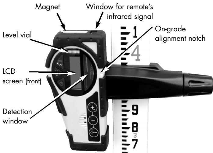
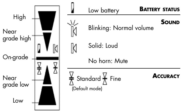
- LCD Display
Detection mode
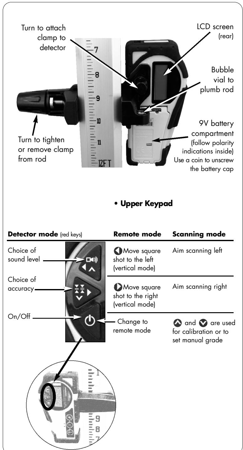
- Press the On/Off key to turn on the detector.
- Press the middle key to select the accuracy (deadband).
- Press the top key to select the sound level.
- Turn the detection window towards the laser beam, and move the detector up or down according to the information given on the LCD display. There are 5 channels of information, or grade indicators.
A down arrow indicates you must move the detector down to reach the laser reference; an up arrow, move it up. When a horizontal line appears on the display, the detector is at the same level as the laser beam.
- Press the On/Off key to turn the detector off. It will automatically shut off after 10 minutes if not used (and give a warning beep).
- Keep the detection window clean, using a soft cloth and glass cleaner.
- Remote control mode
If in detection mode, press On/Off to change to the remote control functions.
If the detector is not on, press any key (except the On/Off) to use it as a remote control for the laser.
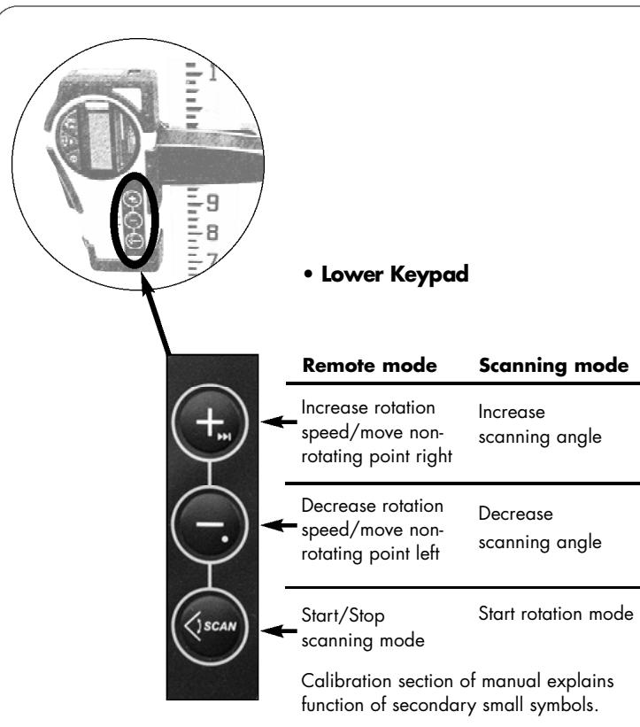
The remote can be used to stop or start rotation, increase or decrease rotation speed, and move the beam or square shot. It also controls scanning and electronic calibration.
- Specifications
| Range* | 500 ft. (150 m) in detection mode
100 ft. (30 m) in remote mode |
| Accuracy* | Fine ± <1/16" (1 mm)
Standard ± 1/8" (2.5 mm) |
| Battery life | 50 hours; 9V alkaline |
| Environmental | Waterproof (IP66+) |
| Size | 6" × 3.25" × 1.5" / 1lb
(15 x 8 x 3.5 cm / 450 g) |
- Varies with laser used. Actual accuracy depends on beam diameter and distance to the laser.
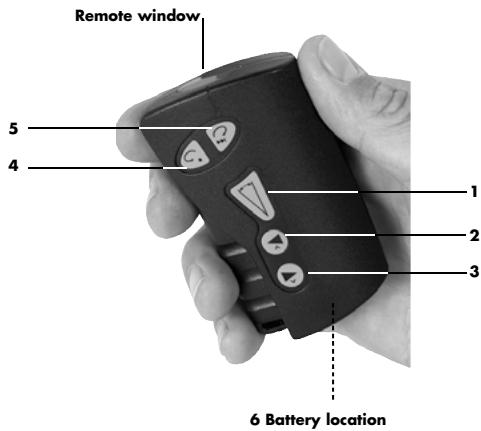
6.2 Remote control
The Remote Control stops, starts, or changes direction of laser rotation, and moves the square shot left or right. It also controls scanning and calibration.
An AA alkaline battery (1.5V) ensures 50 hours of continuous use. To open the battery compartment, push the tab at the top up, in the direction of the arrow (with a screwdriver).
| Beam or chalk line mode | Scanning |
| 1 | | Scan On / Off |
| 2 | Start minimum rotation speed | Increase scan length |
| Move square shot left |
| 3 | Move square shot right | Decrease scan length |
| 4 | Rotation and speed control left | Aim scan left |
| 5 | Rotation and speed control right | Aim scan right |
| 6 | AA Battery | |
To use the remote for calibrating, see pages 10-12.
6.3 Mountains
6.3.1 Universal mount
The universal mount can be used as a wall mount and for vertical setups on a tripod. It features sturdy, all-metal construction, with a springactivated mechanism that allows you to easily change height for quick set-ups. Also, it has a fine adjustment screw on the bottom for precise positionings.
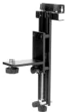
- As a wall mount, it can be attached to a grid for suspended ceiling setup.
- The Mount can also be used on its side and attached to a tripod (5/8-11) to hold the laser in the vertical position.
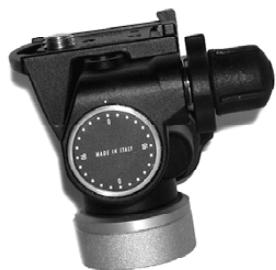
6.3.2 Grade mount
Adjustable grade mount is used to lay out inclined planes, such as cathedral ceilings. Laser must be in manual mode when using the Grade mount.
6.3.3 Tripods
The laser can be mounted on a 5/8-11 flat head tripod. You can also use a tripod with an elevating column to adjust the height of the laser.
6.4 Other accessories
Universal mount
- Laser-enhancing glasses improve the visibility of the laser beam in bright light conditions.
- CB60 red magnetic target improves the visibility of the laser beam in bright conditions.
Quickly attaches to any metallic surface.
Thakita
SKR301
1.2 Technical Specifications

Always recycle batteries
The laser must be calibrated to bring the beam to the centre of the two marks (Steps 3-4 in 3.1.1). The calibration is easily done using the laser keypad, remote control, or detector.
Calibration en X
3.2.2 Calibration plan vertical
Always recycle batteries

Do not discard batteries into garbage can or the like
Aufladen des Akkus
Always recycle batteries

Do not discard batteries into garbage can or the like
Always recycle batteries

Do not discard batteries into garbage can or the like
Trocar as pilhas
Only for EU countries
Do not dispose of electric equipment together with household waste material!
In observance of European Directive 2002/96/EC on waste electrical and electronic equipment and its implementation in accordance with national law, electric equipment that have reached the end of their life must be collected separately and returned to an environmentally compatible recycling facility.
Eeslonia