
C355BEE - Integrated amplifier NAD - Free user manual and instructions
Find the device manual for free C355BEE NAD in PDF.
| Product Type | Stereo Integrated Amplifier |
| Brand | NAD |
| Model | C355BEE |
| Dimensions (W x H x D) | 435 x 116 x 292 mm (net) Overall dimensions: 435 x 130 x 338 mm |
| Net Weight | 8.5 kg |
| Mains Power | 120 V~60 Hz (North American version) Max power consumption: 120 W |
| Output Power | 80 W per channel into 8 Ω (20 Hz - 20 kHz, < 0.02% THD) |
| Total Harmonic Distortion | < 0.02% (20 Hz - 20 kHz, 250 mW to rated power) |
| Signal-to-Noise Ratio | 105 dB (ref. 1 W, A-weighted) 124 dB (ref. rated power) |
| Frequency Response | 20 Hz - 20 kHz, ±0.1 dB |
| Input Impedance (Line) | 200 kΩ + 100 pF |
| Input Sensitivity | 300 mV (ref. rated power) |
| Audio Inputs | 6 line inputs: DISC/MP, CD, VIDEO, AUX, TUNER, TAPE 2, TAPE MONITOR |
| Speaker Outputs | 2 pairs: A and B (binding posts, accept bare wire, spade, banana) |
| Preamp Outputs | PRE OUT 1 and PRE OUT 2 (RCA) |
| Headphone Output | 6.35 mm stereo jack |
| Remote Control | SR 6 (infrared, AAA batteries included) |
| Special Features | Soft Clipping™, Tone Defeat, tone control (bass/treble), balance, motorized volume, RS-232, 12V trigger, IR in/out |
| Included Accessories | SR 6 remote control, AAA batteries (x2), user manual, PRE OUT 2 / MAIN IN jumpers |
| Care and Cleaning | Disconnect before cleaning. Use a damp cloth (mild soapy water if necessary). Do not use liquid or aerosol cleaners. |
| Safety Instructions | Do not open the casing. No user-serviceable parts inside. Avoid moisture. Ensure free ventilation (10 cm sides/rear, 50 cm above). |
| Reparability | Refer all servicing to qualified personnel. Use replacement parts recommended by the manufacturer. |
Frequently Asked Questions - C355BEE NAD
User questions about C355BEE NAD
0 question about this device. Answer the ones you know or ask your own.
Ask a new question about this device
Download the instructions for your Integrated amplifier in PDF format for free! Find your manual C355BEE - NAD and take your electronic device back in hand. On this page are published all the documents necessary for the use of your device. C355BEE by NAD.
USER MANUAL C355BEE NAD
Owner's Manual
- Read instructions - All the safety and operating instructions should be read before the product is operated.
- Retain instructions - The safety and operating instructions should be retained for future reference.
- Heed Warnings - All warnings on the product and in the operating instructions should be adhered to.
- Follow Instructions - All operating and use instructions should be followed.
- Cleaning - Unplug this product from the wall outlet before cleaning. Do not use liquid cleaners or aerosol cleaners. Use a damp cloth for cleaning.
- Attachments - Do not use attachments not recommended by the product manufacturer as they may cause hazards.
- Water and Moisture - Do not use this product near water-for example, near a bath tub, wash bowl, kitchen sink, or laundry tub; in a wet basement; or near a swimming pool; and the like.
- Accessories - Do not place this product on an unstable cart, stand, tripod, bracket, or table. The product may fall, causing serious injury to a child or adult and serious damage to the product. Use only with a cart, stand, tripod, bracket, or table recommended by the manufacturer, or sold with the product. Any mounting of the product should follow the manufacturer's instructions, and should use a mounting accessory recommended by the manufacturer.
- Cart - A product and cart combination should be moved with care. Quick stops, excessive force, and uneven surfaces may cause the product and cart combination to overturn.
- Ventilation - Slots and openings in the cabinet are provided for ventilation to ensure reliable operation of the product and to protect it from overheating. These openings must not be blocked or covered. The openings should never be blocked by placing the product on a bed, sofa, rug, or other similar surface. This product should not be placed in a built-in installation such as a bookcase or rack unless proper ventilation is provided or the manufacturer's instructions have been adhered to.
- Power Sources - This product should be operated only from the type of power source indicated on the marking label and connected to a MAINS socket outlet. If you are not sure of the type of power supply to your home, consult your product dealer or local power company.
- Power-Cord Protection - Power-supply cords should be routed so that they are not likely to be walked on or pinched by items placed upon or against them, paying particular attention to cords at plugs, convenience receptacles, and the point where they exit from the product.
- Mains Plug - Where the mains plug or an appliance coupler is used as the disconnect device, the disconnect device shall remain readily operable.
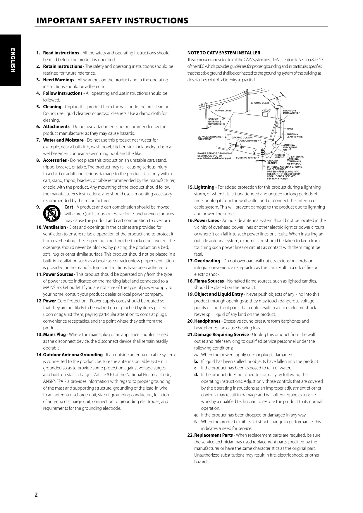
- Outdoor Antenna Grounding - If an outside antenna or cable system is connected to the product, be sure the antenna or cable system is grounded so as to provide some protection against voltage surges and built-up static charges. Article 810 of the National Electrical Code, ANSI/NFPA 70, provides information with regard to proper grounding of the mast and supporting structure, grounding of the lead-in wire to an antenna discharge unit, size of grounding conductors, location of antenna discharge unit, connection to grounding electrodes, and requirements for the grounding electrode.
NOTE TO CATV SYSTEM INSTALLER
This reminder is provided to call the CATV system installer's attention to Section 820-40 of the NEC which provides guidelines for proper grounding and, in particular, specifies that the cable ground shall be connected to the grounding system of the building, as close to the point of cable entry as practical.
- Lightning - For added protection for this product during a lightning storm, or when it is left unattended and unused for long periods of time, unplug it from the wall outlet and disconnect the antenna or cable system. This will prevent damage to the product due to lightning and power-line surges.
- Power Lines - An outside antenna system should not be located in the vicinity of overhead power lines or other electric light or power circuits, or where it can fall into such power lines or circuits. When installing an outside antenna system, extreme care should be taken to keep from touching such power lines or circuits as contact with them might be fatal.
- Overloading - Do not overload wall outlets, extension cords, or integral convenience receptacles as this can result in a risk of fire or electric shock.
- Flame Sources - No naked flame sources, such as lighted candles, should be placed on the product.
- Object and Liquid Entry - Never push objects of any kind into this product through openings as they may touch dangerous voltage points or short-out parts that could result in a fire or electric shock. Never spill liquid of any kind on the product.
- Headphones - Excessive sound pressure form earphones and headphones can cause hearing loss.
- Damage Requiring Service - Unplug this product from the wall outlet and refer servicing to qualified service personnel under the following conditions:
a. When the power-supply cord or plug is damaged.
b. If liquid has been spilled, or objects have fallen into the product.
c. If the product has been exposed to rain or water.
d. If the product does not operate normally by following the operating instructions. Adjust only those controls that are covered by the operating instructions as an improper adjustment of other controls may result in damage and will often require extensive work by a qualified technician to restore the product to its normal operation.
e. If the product has been dropped or damaged in any way.
f. When the product exhibits a distinct change in performance—this indicates a need for service.
-
Replacement Parts - When replacement parts are required, be sure the service technician has used replacement parts specified by the manufacturer or have the same characteristics as the original part. Unauthorized substitutions may result in fire, electric shock, or other hazards.
-
Battery Disposal - When disposing of used batteries, please comply with governmental regulations or environmental public instruction's rules that apply in your country or area. Batteries (battery pack or batteries installed) must not be exposed to excessive heat such as sunshine, fire or the like.
- Safety Check - Upon completion of any service or repairs to this product, ask the service technician to perform safety checks to determine that the product is in proper operating condition.
- Wall or Ceiling Mounting - The product should be mounted to a wall or ceiling only as recommended by the manufacturer.
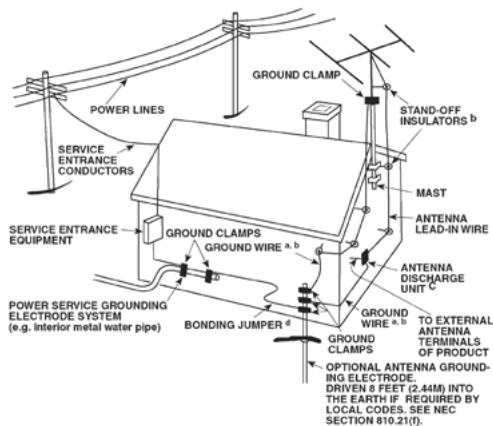
WARNING

The lightning flash with arrowhead symbol, within an equilateral triangle, is intended to alert the user to the presence of uninsulated "dangerous voltage" within the product's enclosure that may be of sufficient magnitude to constitute a risk of electric shock to persons

The exclamation point within an equilateral triangle is intended to alert the user to the presence of important operating and maintenance (servicing) instructions in the literature accompanying the appliance.
WARNING: TO REDUCE THE RISK OF FIRE OR ELECTRIC SHOCK, DO NOT EXPOSE THIS APPARATUS TO RAIN OR MOISTURE AND OBJECTS FILLED WITH LIQUIDS, SUCH AS VASES, SHOULD NOT BE PLACED ON THIS APPARATUS.
CAUTION REGARDING PLACEMENT
To maintain proper ventilation, be sure to leave a space around the unit (from the largest outer dimensions including projections) than is equal to, or greater than shown below.
Left and Right Panels: 10 cm
Rear Panel: 10 cm
Top Panel: 50 cm
IMPORTANT INFORMATION TO UK CUSTOMERS
DO NOT cut off the mains plug from this equipment. If the plug fitted is not suitable for the power points in your home or the cable is too short to reach a power point, then obtain an appropriate safety approved extension lead or consult your dealer. If nonetheless, the mains plug is cut off, REMOVE THE FUSE and dispose of the PLUG immediately, to avoid possible shock hazard by inadvertent connection to the mains supply. If this product is not provided with a mains plug, or one has to be fitted, then follow the instructions given below:
IMPORTANT
DO NOT make any connection to the larger terminal which is marked with the letter 'E' or by the safety earth symbol or colored GREEN or GREEN AND YELLOW. The wires in the mains lead on this product are colored in accordance with the following code:
BLUE - NEUTRAL
BROWN - LIVE
As these colors may not correspond with the colored markings identifying the terminals in your plug, proceed as follows:
- The BLUE wire must be connected to the terminal marked with the letter 'N' or colored BLACK.
- The BROWN wire must be connected to the terminal marked with the letter 'L' or colored RED
- When replacing the fuse, only a correctly rated and approved type should be used, and be sure to re-fit the fuse cover.
IF IN DOUBT CONSULT A COMPETENT ELECTRICIAN.

This product is manufactured to comply with the radio interference requirements of EEC DIRECTIVE 2004/108/EC.
NOTES ON ENVIRONMENTAL PROTECTION

At the end of its useful life, this product must not be disposed of with regular household waste but must be returned to a collection point for the recycling of electrical and electronic equipment. The symbol on the product, user's manual and
packaging point this out.
The materials can be reused in accordance with their markings. Through re-use, recycling of raw materials, or other forms of recycling of old products, you are making an important contribution to the protection of our environment.
Your local administrative office can advise you of the responsible waste disposal point.
RECORD YOUR MODEL NUMBER (NOW, WHILE YOU CAN SEE IT)
The model and serial number of your new C 355BEE are located on the back of the cabinet. For your future convenience, we suggest that you record these numbers here:
Model number:
Serial number:
GETTING STARTED
UNPACKING AND SETUP
WHAT'S IN THE BOX
Packed with your C 355BEE you will find:
• The SR 6 remote control with 2 (two) AAA batteries
• This owner's manual
SAVE THE PACKAGING
Please save the box and all of the packaging in which your C 355BEE arrived. Should you move or otherwise need to transport your receiver, this is by far the safest container in which to do so. We've seen too many otherwise perfect components damaged in transit for lack of a proper shipping carton, so please: Save that box!
CHOOSING A LOCATION
Choose a location that is well ventilated (with at least several inches to both sides and behind), and that will provide a clear line of sight, within 25 feet/8 meters, between the C 355BEE's front panel and your primary listening/viewing position. This will ensure reliable infrared remote control communications. The C 355BEE generates a modest amount of heat, but nothing that should trouble adjacent components. It is perfectly possible to stack the C 355BEE on top of other components.
NOTES ON INSTALLATION
Your NAD C 355BEE should be placed on a firm, level surface. Avoid placing the unit in direct sunlight or near sources of heat and damp. Allow adequate ventilation. Do not place the unit on a soft surface like a carpet. Do not place it in an enclosed position such a bookcase or cabinet that may impede the air-flow through the ventilation slots. Make sure the unit is switched off before making any connections.
The RCA sockets on your NAD C 355BEE are colour coded for convenience. Red and white are Right and Left audio respectively.
Use high quality leads and sockets for optimum performance and reliability. Ensure that leads and sockets are not damaged in any way and all sockets are firmly pushed home.
For best performance, use quality speaker leads of 16 gauge (1.5mm) thickness or more. If the unit is not going to be used for some time, disconnect the plug from the AC socket.
Should water get into your NAD C 355BEE, shut off the power to the unit and remove the plug from the AC socket. Have the unit inspected by a qualified service technician before attempting to use it again.
DO NOT REMOVE THE COVER, THERE ARE NO USER-SERVICEABLE PARTS INSIDE.
Use a dry soft cloth to clean the unit. If necessary, lightly dampen the cloth with soapy water. Do not use solutions containing benzol or other volatile agents.
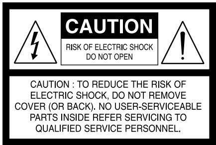
BARE WIRES AND PIN CONNECTORS

WARNING: The terminals marked with this symbol are hazardous live. External wiring connected to these terminals requires installation by an instructed person or the use of ready-made leads or cords.
Bare wires and pin sockets should be inserted into the hole in the shaft of the terminal. Unscrew the speaker terminal's plastic bushing until the hole in the screw shaft is revealed. Insert the pin or bare cable end into the hole and secure the cable by tightening down the terminal's bushing. Ensure bare wire from the speaker cables does not touch the back panel or another socket. Ensure that there is only 1/2" (1cm) of bare cable or pin and no loose strands of speakers wire.
QUICK START
In case you simply cannot wait to experience the performance of your new NAD C 355BEE, we provide the following "Quick Start" instructions to get you underway.
Please make all the connections to your C 355BEE with the unit unplugged. It is also advisable to power-down or unplug all associated components while making or breaking any signal or AC power connections.
1 Connect the speakers to the rear Speaker terminals and sources to the relevant rear input sockets.
2 Plug in the AC power cord.
3 Switch the POWER button on the rear panel to ON in order to turn the C 355BEE to standby.
4 Press the front panel Standby button to turn the C 355BEE ON.
5 Press the required input selector.
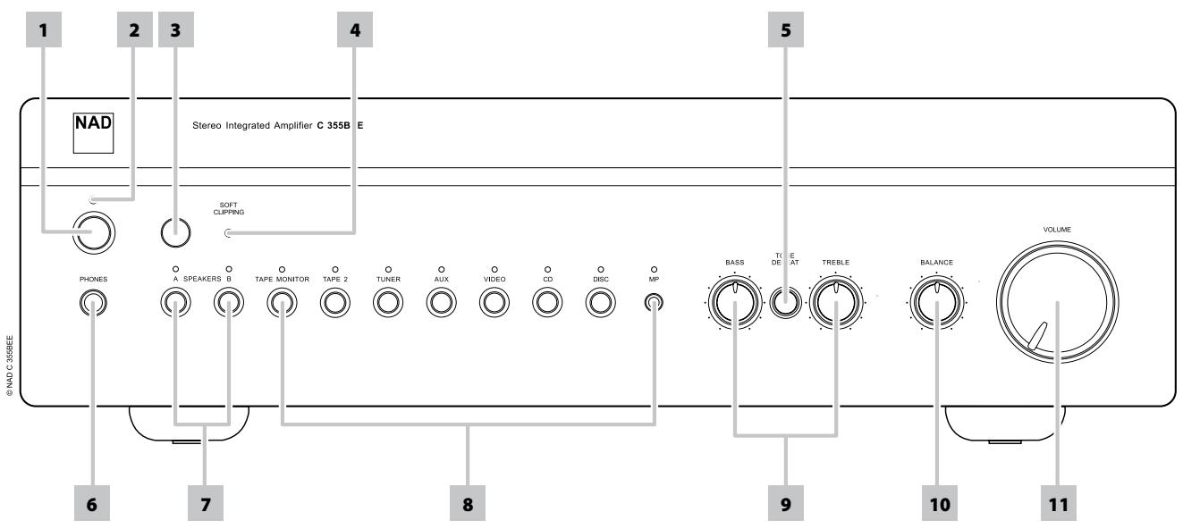
1 STANDBY BUTTON: The Standby Button turns ON and set to standby the C 355BEE. This button will only function when the Power/Standby/Protection LED is either amber representing the standby state, or green representing the ON state.
2 POWER/STANDBY/PROTECTION LED: Upon switching the power ON, the LED will light up red for a few seconds before the protection circuit is deactivated. The LED will then turn green, representing normal operation.
In cases of serious abuse of the amplifier, such as overheating, excessively low loudspeaker impedance, short circuit etc. the amplifier will engage its Protection circuitry, indicated by the LED turning from green to red, and the sound being muted.
In such a case, turn the amplifier off by the rear panel POWER button, wait for it to cool down and/or check the speaker connections, making sure the overall loudspeaker impedance doesn't go below 4 ohms. Once the cause for the protection circuitry to engage has been removed, switch ON the rear POWER button and the Standby Button to resume normal operation.
3 INFRA-RED REMOTE CONTROL COMMAND RECEIVER: The infrared sensor, located behind this circular window, receives commands from the remote control. There must be a clear line-of-sight path from the remote control to this window; if that path is obstructed, the remote control may not work.
NOTE
Direct sunlight or very bright ambient lighting may affect the operating range and angle for the remote control handset.
4 SOFT CLIPPING INDICATOR: The green Soft Clipping LED shows that the Soft Clipping mode is engaged. Refer also to "IDENTIFICATION OF CONTROLS - REAR PANEL, item 14 Soft Clipping" for more information.
5 TONE DEFEAT: The TONE DEFEAT switch bypasses the tone control section of the NAD C 355BEE. If the Tone Controls are not normally used and left in the 12 o'clock position, then it is advisable to switch out the Tone Control section altogether by using this switch. In the 'out' position, the Tone Control circuits are active; pushing the TONE DEFEAT switch 'in' bypasses the Tone Control section.
6 HEADPHONE SOCKET: A 1/4" stereo jack socket is supplied for headphone listening and will work with conventional headphones of any impedance. The headphone socket will work in parallel to the selected speakers. To listen to headphones only, de-select Speakers A and/or B. The volume, tone and balance controls are operative for headphone listening. Use a suitable adapter to connect headphones with other types of sockets, such as 3.5mm stereo 'personal stereo' jack plugs.
WARNING
Make certain that the volume control is turned to minimum (fully counter-clockwise) before connecting or disconnecting headphones. Listening at high levels can damage your hearing.
7 A SPEAKERS B: The Speakers A and B buttons engage or disengage the speakers connected respectively to the Speakers A and Speakers B terminals on the rear panel. Press "A" to switch ON or OFF the speakers connected to the speaker A terminals. Press B to switch ON or OFF the speakers connected to the speaker B terminals. The indicator directly over the buttons shows the status of Speakers A and B.
FRONT PANEL
8 INPUT SELECTORS: These buttons select the active input to the NAD C 355BEE and the signal sent to the loudspeakers, the Tape outputs and the PRE OUT sockets. The buttons on the remote control handset duplicate these buttons. Green LEDs just above each button will indicate which input is currently selected.
DISC/MP (Media Player): Selects a line-level source connected to the DISC sockets as the active input. When a 3.5mm stereo plug is inserted into the MP socket, the indicator above the socket will illuminate, and the DISC line-level source will be disconnected. It is recommended to mute the volume or switch to a different input before plugging/unplugging the external Media Player cable.
CD : Selects the CD (or other line-level source) connected to the CD sockets as the active input.
VIDEO : Selects the VCR (or stereo TV/Satellite/Cable receiver) connected to the VIDEO sockets as the active input.
AUX: Selects a line-level source connected to the AUX sockets as the active input.
TUNER: Selects the tuner (or other line-level source) connected to the tuner sockets as the active input.
TAPE 2: Selects Tape 2 as the active input.
TAPE MONITOR : Selects the output from a tape recorder when playing back tapes or monitoring recordings being made through the Tape Monitor sockets. Press the Tape Monitor button once to select it and again to return to the normal input selection.
TAPE MONITOR does not override the current input selection. For example, if CD is the active input when TAPE Monitor is selected, then the CD signal will continue to be selected and sent to both the TAPE 2 and TAPE MONITOR OUTPUT sockets, but it is the sound from recorder connected to Tape Monitor that will be heard on the loudspeakers. Apart from the amber LED to indicate Tape Monitor is engaged, the green LED for the active input will also stay lit.
NOTE
The remote control handset with the C 355BEE supplied is of a universal NAD type, designed to operate several NAD models. Some buttons on this handset are inoperative as the functions aren't supported by the C 355BEE. The Video 2 and Video 3 input selector buttons on the remote control handset are inoperative in the case of the C 355BEE.
9 TONE CONTROLS: The NAD C 355BEE is fitted with BASS and TREBLE tone controls to adjust the tonal balance of your system. The 12 o'clock position is 'flat' with no boost or cut, and an indent indicates this position. Rotate the control clockwise to increase the amount of Bass or Treble. Rotate the control anti-clockwise to decrease the amount of Bass or Treble. The Tone controls do not affect recordings made using the Tape outputs but will affect the signal going to the Pre-amp output (PRE OUT 1 or PRE OUT 2).
10 BALANCE: The BALANCE control adjusts the relative levels of the left and right speakers. The 12 o'clock position provides equal level to the left and right channels. A detent indicates this position. Rotating the control clockwise moves the balance towards the right. Rotating the control anti-clockwise moves the balance to the left. The BALANCE control does not affect recordings made using the Tape outputs but will affect the signal going to the Pre-amp output (PRE OUT 1 or PRE OUT 2).
11 VOLUME: The VOLUME control adjusts the overall loudness of the signals being fed to the loudspeakers. It is motor driven and can be adjusted from the remote control handset. The VOLUME control does not affect recordings made using the Tape outputs but will affect the signal going to the Pre-amp output (PRE OUT 1 or PRE OUT 2). On the remote control handset, press the MUTE button to temporarily switch OFF the sound to the speakers and headphones. Mute mode is indicated by the Power/Standby/Protection LED flashing. Press the MUTE button again to restore sound. Mute does not affect recordings made using the Tape outputs but will affect the signal going to the Pre-amp output (PRE OUT 1 or PRE OUT 2).
ATTENTION!
Please make sure that the C 355BEE is powered OFF or unplugged before making any connections. It is also advisable to power-down or unplug all associated components while making or breaking any signal or AC power connections.
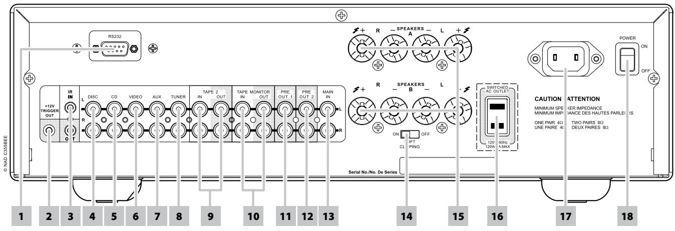
1 RS-232: Connect this interface via RS-232 serial cable (not supplied) to any Windows® compatible PC to allow remote control of the C 355BEE through NAD's proprietary PC software or other compatible external controllers. NAD is a certified partner of AMX and Crestron and fully supports these external devices. See your NAD audio specialist for more information.
2 12V TRIGGER OUTPUT: The 12V TRIGGER OUTPUT is used for controlling external equipment that is equipped with a 12V trigger input. This output will be 12V when the C 355BEE is ON and 0V when the unit is either OFF or in standby. This output can drive a load up to 50mA at 12V.
3 IR IN/OUT: These mini-jacks accept and output remote-controlled codes in electrical format, using industry-standard protocols, for use with "IR-repeater" and multi-room systems and related technologies.
IR IN: This input is connected to the output of an IR (infrared) repeater (Xantech or similar) or the IR output of another component to allow control of the C 355BEE from a remote location.
IR OUT : When connected to the IR IN of an ancillary equipment, direct the ancillary equipment's own remote control to the C 355BEE's infrared receiver to command or control the linked unit.
All NAD products with IR IN/IR OUT features are fully compatible with the C 355BEE. For non-NAD models, please check with your other product's service specialists as to their compatibility to the C 355BEE's IR features.
4 DISC INPUT: Input for additional line level input signals such as CD, Mini Disc player or the output signal from a step-up amplifier for a turntable. Use a twin RCA-to-RCA lead to connect the auxiliary unit's left and right 'Audio Outputs' to this input.
NOTE
When a 3.5mm stereo plug is inserted into the Front Panel MP socket, the indicator above the socket will illuminate, and the DISC line-level source will be disconnected. It is recommended to mute the volume or switch to a different input before plugging/unplugging the external Media Player cable.
5 CD INPUT: Input for a CD or other line-level signal source. Use a twin RCA-to-RCA lead to connect the CD player's left and right 'Audio Outputs' to this input. The NAD C 355BEE only accepts analogue signals from your CD player.
6 VIDEO INPUT: Input for the audio signal from a stereo VCR (or stereo TV/Satellite/Cable receiver) or other line-level audio source. Using twin RCA-to-RCA leads, connect to the left and right 'Audio Outputs' of the unit to these inputs.
NOTE
These are audio inputs only.
7 AUX INPUT: Input for additional line level input signals such as another CD player. Use a twin RCA-to-RCA lead to connect the auxiliary unit's left and right 'Audio Outputs' to this input.
8 TUNER INPUT: Input for a tuner or other line-level signal source. Use a twin RCA-to-RCA lead to connect the tuner left and right 'Audio Outputs' to this input.
REAR PANEL
9 TAPE 2 IN/OUT: Connections for analogue recording and playback to an audio tape recorder of any type. Using twin RCA-to-RCA leads, connect to the left and right 'Audio Output' of the tape machine to the TAPE 2 IN sockets for playback and tape monitoring. Connect the left and right 'Audio Input' of the tape machine to the TAPE 2 OUT sockets for recording.
10 TAPE MONITOR IN/OUT: Connections for analogue recording and playback to a secondary audio tape recorder of any type. Using twin RCA-to-RCA leads, connect to the left and right 'Audio Output' of the tape machine to the TAPE MONITOR IN sockets for playback and tape monitoring. Connect the left and right 'Audio Input' of the tape machine to the TAPE MONITOR OUT sockets for recording.
TO MAKE A RECORDING
When any source is selected, its signal is also fed directly to any tape machine connected to the TAPE 2 OUT or TAPE MONITOR OUT for recording.
TAPE TO TAPE COPYING
You can copy between two tape machines connected to your NAD C 355BEE. Put the source tape in the recorder connected to Tape 2 and the blank tape into the recorder connected to Tape Monitor. By selecting TAPE 2 input you can now record from Tape 2 to Tape Monitor and monitor the signal coming from the original tape.
NOTE
There will be no Tape 2 output when Tape 2 (or Tape Monitor OUT when Tape Monitor) is the selected source input. This prevents feedback through the recording component thereby preventing possible damage to your speakers.
11 PRE OUT 1: The PRE OUT 1 sockets can be used to drive an additional power amplifier. Use a twin RCA-to-RCA lead to connect to the left and right 'Audio Input' of the Power amplifier or processor to the PRE OUT 1 sockets.
12 PRE OUT 2: Connections to an external power amplifier or processor, such as a surround-sound decoder. In normal use, these should be connected to the Main-In sockets (No. 13) with the links supplied. To connect your NAD C 355BEE to external processor or amplifier sections, remove first these links. Use a twin RCA-to-RCA lead to connect to the left and right 'Audio Input' of the Power amp or processor to the PRE OUT 2 sockets.
NOTE
Always turn the C 355BEE and associated external power amplifiers OFF before connecting or disconnecting anything to the PRE OUT 1, 2 and MAIN IN sockets. The PRE OUT 1 and 2 output signals will be affected by the C 355BEE's volume and tone control settings.
13 MAIN IN: Connections to an external pre-amplifier or processor, such as a surround-sound decoder. In normal use, these should be connected to PRE OUT 2 sockets (No. 12) with the links supplied. To connect your NAD C 355BEE to external processor or pre-amplifier first remove these links. Use a twin RCA-to-RCA lead to connect to the left and right 'Audio Output' of the pre-amp or processor to the Main-In sockets.
NOTE
Always turn the amplifier off before connecting or disconnecting anything from to PRE OUT 1, 2 and MAIN IN sockets.
14 SOFT CLIPPING™: When an amplifier is driven beyond its specified power output, a hard, distorted sound can be heard on very loud sounds. This is caused by the amplifier cutting off or 'hard clipping' the peaks of sound that was not designed to reproduce. The NAD Soft Clipping circuit gently limits the output of the system to minimise audible distortion if the amplifier is overdriven. If your listening involves moderate power levels you may leave the Soft Clipping switch to OFF. If you are likely to play at high levels, that could stretch the amplifier's power capability, then switch Soft Clipping ON. The Soft Clipping™ LED on the front panel will illuminate when the amplifier is in Soft Clipping mode.
15 SPEAKERS A, B: The C 355BEE is equipped with two sets of speaker connectors. Use the Speakers A connectors for the 'main' speakers and use the Speakers B connectors for a second pair, for example, extension speakers located in another room.
Connect the right speaker to the terminals marked 'R +' and 'R-' ensuring that the 'R+' is connected to the '+' terminal on your loudspeaker and the 'R-' is connected to the loudspeaker's '-' terminal. Connect the terminals marked 'L+' and 'L-' to the left speaker in the same way.
Always use heavy duty (16 gauge; 1.5mm, or thicker) stranded wire to connect loudspeakers to your NAD C 355BEE. The high-current binding post terminals can be used as a screw terminal for cables terminating in spade or pin sockets or for cables with bare wire ends.
16 SWITCHED AC OUTLET (North America version only): The SWITCHED AC OUTLET can supply switched power to another component or accessory. This convenience outlet can be switched ON or OFF using only the POWER switch located at the rear panel. The SWITCHED AC OUTLET cannot be switched ON or OFF using the front panel Standby button or the ON/OFF button of the remote control. The total draw of all devices connected to this Switched AC outlet must not exceed 120 watts.
17 IEC AC MAINS (POWER) INPUT: The C 355BEE comes supplied with a separate AC Mains cable. Before connecting the cable to a live wall socket ensure that it is firmly connected to the NAD C 355BEE's AC Mains input socket first. Always disconnect the AC Mains cable plug from the live wall socket first, before disconnecting the cable from the C 355BEE Mains input socket.
18 POWER SWITCH: The POWER switch supplies the master AC mains power for the C 355BEE. When the switch is in the ON position the C 355BEE is in standby as shown by the amber Status Condition LED, above the Standby button on the front panel. If you intend not to use the amplifier for long periods of time, switch the POWER switch to the OFF position.
natural_image
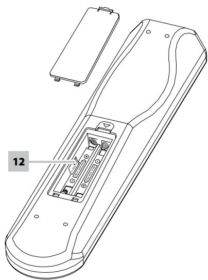
Line drawing of a remote control device with labeled component '12' (no text or symbols beyond label)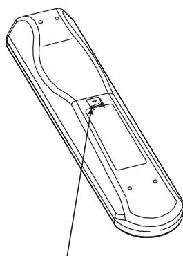
natural_image
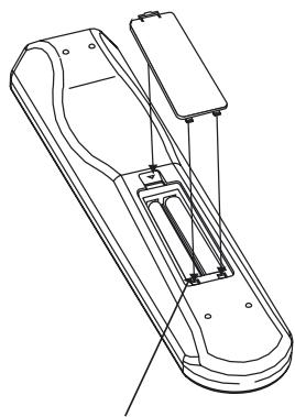
Line drawing of a remote control casing with mounting holes and a handle (no text or symbols)Press in and lift tab to remove battery cover out of recess.

natural_image
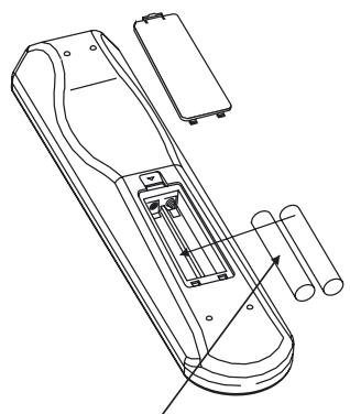
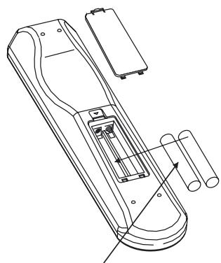
Technical line drawing of a remote control device with attached components (no text or symbols)Place batteries into opening. Ensure the correct fitting is observed.

natural_image
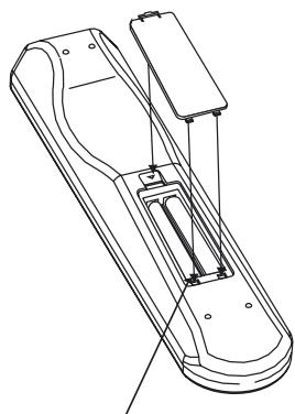
Technical line drawing of a mechanical device with no visible text or symbolsReplace battery cover by aligning and inserting the two tabs into the holes. Press battery cover into place until 'clicks' closed.
SR 6 REMOTE CONTROL
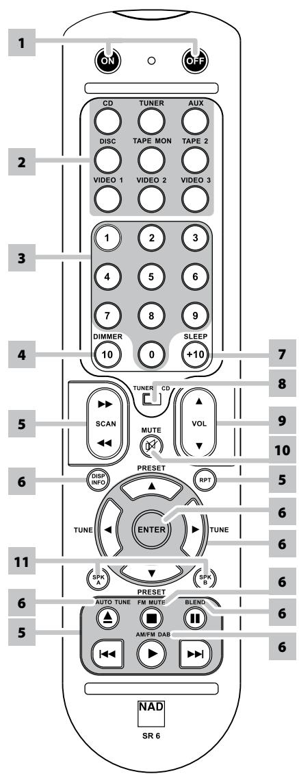
The SR 6 remote control handset handles the key functions of the C 355BEE as well as other NAD Stereo Receivers, Integrated Amplifiers and Preamplifiers. It has additional controls to remotely operate NAD CD Players, FM/AM Tuners and dedicated FM/AM/DAB Tuners. It will operate up to a distance of 16ft (5m). Alkaline batteries are recommended for maximum operating life. Two AAA (R 03) batteries should be fitted in the battery compartment at the rear of the Remote Control handset. When replacing batteries, check that they have been put in the right way round, as indicated on the base of the battery compartment.
When a command from the remote control is received, the Standby/protection indicator will blink. Note that the indicator may also blink when receiving commands not necessarily for the C 355BEE but for other components in the system. Please refer to previous sections of the manual for a full description of individual functions.
1 POWER ON & OFF: The SR 6 remote has a separate ON and OFF button. This can be particularly useful to keep components within a system "in sync": This way all components will switch to standby when OFF is pressed or switched to operating mode when ON is pressed - instead of some components switching ON when the C 355BEE is switched to Standby. (Note that the other components have to be capable of responding to the separate ON and OFF commands as well).
Press the ON button to switch the unit from Standby to operating mode; The Power/Standby/Protection LED indicator will turn from amber, to red, then to green and the indicator for the last selected input will blink and light up. Press the OFF button to switch the unit to Standby mode: The Power/Standby/Protection LED indicator will light up amber.
2 INPUTS: The input selector buttons perform the same functions as the buttons labeled the same on the front panel.
3 NUMERIC KEYS: The numeric keys allow for direct input of tracks for CD players, and direct channel/preset access for tuners and receivers.
4 DIMMER: Press this button to dim the front panel display. Depending on the NAD model, the brightness of the front panel display will vary when you toggle this button.
5 CD PLAYER CONTROL (for use with NAD CD Player)
II engages Pause
■ engages Stop
▶ engages Play
««/» engages reverse or forward Scan
|◀◀/▶▶|engages reverse of forward Skip
▲ engages CD drawer Open/Close; Press once to open the CD drawer then once again to close the CD drawer
RPT. This button engages the Repeat Play mode for disc playback. Toggle to repeat one track, repeat all tracks or turn off repeat play mode.
6 TUNER CONTROL (for use with NAD AM/FM/DAB Tuner)
TUNE: ◀ or ▶ scans respectively higher or lower station frequencies for both AM and FM.
PRESET ▲ or ▼: Selects respectively higher or lower number station preset.
DISP/INFO: Repeatedly pressing this button will show information as supplied by the current radio station. The applicable display contents include related DAB display information and RDS broadcast data.
ENTER: With a dedicated FM/AM/DAB tuner, toggle this button to select manual tune, preset tune or auto tune.
AUTO TUNE: In DAB mode, press this button to automatically scan all available local stations.
FM MUTE: In DAB mode, pressing this button will activate Dynamic Range Control, preset tune, manual tune, station order or other appropriate features. In FM mode, press this button to select the stereo or mono mode for FM tuning.
BLEND: The Blend button toggles between engaging and disengaging the Blend feature. The NAD Blend feature will allow you to reduce the amount of noise and hiss normally associated with received weak radio stations but still retain some level of stereo separation, instead of mono.
AM/FM/DAB: In tuner mode, toggle this button to switch to DAB, FM and AM frequency bands.
7 SLEEP: Press SLEEP to switch off the applicable tuner after a preset number of minutes. Each consecutive press will reduce the sleep time in preset increments until sleep mode is cancelled as could be shown in the front panel display.
8 TUNER/CD: The TUNER/CD switch applies relevant tuner controls when in the TUNER position, and applies CD controls to the appropriate buttons when in the CD position.
9 VOLUME: Press VOLUME ▲ or ▼ buttons to respectively increase or decrease the loudness level. Release the button when the desired level is reached. The motorised Volume control on the front panel will indicate the level set. The Volume buttons do not affect recordings made using the Tape outputs but will affect the signal going to the Pre-amp outputs.
10 MUTE: Press the MUTE Button to temporarily switch OFF the sound to the speakers and headphones. MUTE mode is indicated by the Power/Standby/Protection LED indicator on the front panel flashing. Press MUTE again to restore sound. Mute does not affect recordings made using the Tape outputs but will affect the signal going to the Preamp outputs.
11 SPK A, SPK B: The SPK A and SPK B buttons engage or disengage the speakers connected respectively to the C 355BEE's Speakers A and Speakers B terminals. Toggle SPK A to switch ON or OFF the speakers connected to the speaker A terminals. Toggle SPK B to switch ON or OFF the speakers connected to the speaker B terminals. Press both buttons to engage both speakers.
12 DEV 1/DEV 2: The default setting for this SR 6 remote control is set to DEV 1. In this position, the Tuner/CD switch allows for both CD control and AM/FM Tuner functions. If one switches to DEV 2, the applicable buttons will remain for CD control buttons and now for dedicated AM/FM/DAB Tuner functions.
| CONDITION | POSSIBLE CAUSES | POSSIBLE SOLUTIONS |
| No sound. | Power AC lead unplugged or power not switched ON. | Check if AC lead is plugged in and power switched ON. |
| Tape Monitor selected. | De-select Tape Monitor mode. | |
| Mute on. | Switch off Mute. | |
| Rear Pre-out/Main-in amp links not fitted. | Fit links. | |
| Headphones inserted. | Disconnect headphones. | |
| No sound one channel. | Balance control not centered. | Center Balance control. |
| Speaker not properly connected or damaged. | Check connections and speakers. | |
| Input lead disconnected or damaged. | Check leads and connections. | |
| Weak bass / diffused stereo image. | Speakers wired out of phase. | Check connections to all speakers in the system. |
| Remote control handset not working. | Battery flat or incorrectly inserted. | Check or replace battery. |
| IR transmitter or receiver windows obstructed. | Remove obstruction. | |
| IR receiver in direct sun or very bright ambient light. | Place unit away from direct sun, reduce amount of ambient light. | |
| Power / Stand-by / Protection LED turns red during operation. | Amplifier has overheated. | Turn amplifier OFF; make sure ventilation slots on top and bottom of amplifier are not blocked. After amplifier has cooled down, turn back ON. |
| Overall impedance of loudspeakers too low. | Ensure the overall loudspeaker impedance is not below 4 ohms. |
SPECIFICATIONS
PREAMPLIFIER SECTION
LINE LEVEL INPUTS (DISC, CD, VIDEO, AUX, TUNER, TAPE MONITOR, TAPE2)
| Input impedance (R and C) | 200k KΩ+ 100pF |
| Input sensitivity (ref. rated power) | 300mV |
| Maximum input signal | 6V |
| Signal / Noise ratio A-weighted1 | 98.0dB ref. 1W |
| Signal / noise ratio pre-amp out, A-weighted | 110dB ref. 500mV |
| Frequency response 20Hz - 20kHz | <±0.1dB (Tone defeat on) |
| <±0.1dB (Tone defeat off) |
| THD + Noise, SMPTE IM | < 0.01% at 5V out |
LINE LEVEL OUTPUTS
| Output impedance - Pre-out | 80 Ω |
| Tape | Source Z + 1kΩ |
| Maximum output level - Pre-out | >11V |
| Tape | >10V |
TONE CONTROLS
| Treble | ±5dB at 10kHz |
| Bass | ±8dB at 100Hz |
TRIGGER OUT
| Output resistance | <120 Ω |
| Output current | 50mA |
| Output voltage | 12V |
POWER AMPLIFER SECTION
| Continuous output power into 8 ^2 | 80W (19dBW) |
| Rated distortion (THD 20Hz - 20kHz) | 0.02% |
| Clipping power (maximum continuous power per channel 4 Ω and 8 Ω) | 92W |
| IHF Dynamic headroom - 8 Ω | +2.4dB |
| 4 Ω | +4.4dB |
| IHF dynamic power (maximum short term power per channel) - 8 Ω | 140W (21.5dBW) |
| 4 Ω | 220W (23.4dBW) |
| 2 Ω | 270W (24.3dBW) |
| Damping factor (ref. 8 Ω, 1kHz) | >160 |
| Input impedance (R & C) | 20kΩ+ 1nF |
| Input sensitivity (rated output into 8 Ω) | 940mV |
| Voltage gain | 29dB |
| Frequency response 20Hz - 20kHz | ±0.1dB |
| Signal/noise ratio, A-weighted | 105dB (ref. 1W) |
| 124dB (ref. rated power) |
| THD + Noise3 | <0.02% |
| SMPTE IM4 | <0.01% |
| IHF IM5 | <0.01% |
| Headphone output impedance | 68 Ω |
PHYSICAL SPECIFICATIONS
| Dimensions (W x H x D) - Net | 435 x 116 x 292mm |
| Gross6 | 435 x 130 x 338mm |
| Net weight | 8.5kg |
| Shipping weight | 10.4kg |
1 From CD input to speakers output, volume setting for 500mV in, 8 Ω 1W out
2 Minimum power per channel, 20Hz - 20kHz, both channels driven with no more than rated distortion.
3 Total harmonic distortion, 20Hz - 20kHz from 250mW to rated output
4 Intermodulation distortion, 60Hz + 7kHz, 4:1, from 250mW to rated output
5 CCIF IM distortion, 19.5K+1kHz rated output
6 Gross dimensions include feet, volume knob and extended speaker terminals.
Specifications are subject to change without notice. For updated documentation and features, please log onto www.NADElectronics.com for the latest information about C 355BEE.
CHOIX D'UN EMPLACEMENT
natural_image
Line drawing of a remote control device with labeled component '12' (no text or symbols beyond label)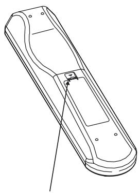
natural_image
Line drawing of a remote control device with handle and mounting bracket (no text or symbols)ENFONCEZ ET RELEVEZ LA LANGUETTE POUR RETIRER LE COUVERCLE DU COMPARTIMENT DES PILES.
natural_image
Technical line drawing of a handheld device with internal components and mounting base (no text or symbols)INSÉREZ LES PILES DANS LE COMPARTIMENT. VÉRIFIEZ LA BONNE MISE EN PLACE.

natural_image
Technical line drawing of a mechanical device with no visible text or symbolsREMETTEZ EN PLACE LE COUVERCLE DU COMPARTIMENT DES PILES EN ALIGNMENT LES DEUX LANGUETTES AVEC LES TROUS, PUIS EN LES Y INSÉRANT. APPUYEZ SUR LE COUVERCLE DU COMPARTIMENT DES PILES POUR LE METTRE UN PLACE (VOUS RESSENTIREZ UN DÉCLIC).
TELECOMMANDE SR 6
natural_image
Line drawing of a remote control device with labeled component '12' (no text or symbols beyond label)
natural_image
Line drawing of a remote control device with no text or symbolsEMPUJE Y LEVANTE LA OREJETA PARA RETIRAR LA TAPA DE LAS PILAS FUERA DE LA CAVIDAD.

natural_image
Technical line drawing of a remote control device with attached components (no text or symbols)COLOQUE LAS PILAS EN LAS ABERTURAS. ASEGÚRESE QUE ENCAJAN CORRECTAMENTE.

natural_image
Technical line drawing of a mechanical device with no visible text or symbolsMONTE DE NUEVO LA TAPA DE LAS PILAS ALINEANDO E INSERTANDO LAS DOS OREJETAS EN LOS ORIFICIOS. EMPUJE LA TAPA DE LAS PILAS HASTA QUE HAGA CLIC AL CERRARSE.
MANDO A DISTANCIA SR 6
| Trémolo | ±5dB (10kHz) |
| Bajo | ±8dB (100Hz) |
10 TAPE MONITOR IN, OUT (NASTRO MONITOR IN, OUT):
natural_image
Line drawing of a remote control device with labeled component '12' (no text or symbols beyond label)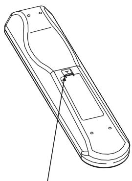
natural_image
Line drawing of a remote control device with no text or symbolsPREMERE E SOLLEVARE LA LINGUETTA PER RIMUOVERE IL COPERCHIO DEL VANO BATTERIE DALLA SUA SEDE
natural_image
Technical line drawing of a remote control device with attached components (no text or symbols)natural_image
Technical line drawing of a mechanical device with no visible text or symbolsRIMETTERE IL COPERCHIO DEL VANO BATTERIE, INSERENDO LE DUE LINGUETTE NEI FORI. PREMERE IL COPERCHIO DEL VANO BATTERIE FINQUANDO UN SCATTO CONFERMA LA CHIUSURA CORRETTA
TELECOMANDO SR 6
| Alti | ±5dB at 10kHz |
| Bassi | ±8dB at 100Hz |
TRIGGER OUT
natural_image
Line drawing of a remote control device with labeled component '12' (no text or symbols beyond label)
natural_image
Line drawing of a remote control device with handle and mounting bracket (no text or symbols)HINEINDRÜCKEN UND ZUM ABNEHMEN DES BATTERIEFACHDECKELS LASCHE ANHEBEN.

natural_image
Technical line drawing of a handheld device with internal components and mounting base (no text or symbols)natural_image
Technical line drawing of a mechanical device with no visible text or symbolsBATTERIEFACHDECKEL DURCH AUSRICHTEN UND EINFÜHREN IN DIE AUSSPARUNGEN WIEDER EINSETZEN. BATTERIEFACHDECKEL HINEINDRÜCKEN BIS ER MIT EINEM HÖRBAREN KLICK SCHLIESST.
FERNBEDIENUNG SR 6
WAARSCHUWING M.B.T. PLAATSING
BEWAAR DE VERPAKKING
17 IEC AC MAINS (POWER) INPUT (INGANG
natural_image
Line drawing of a remote control device with labeled component '12' (no text or symbols beyond label)
natural_image
Line drawing of a remote control device with handle and mounting bracket (no text or symbols)HET LIPJE INDRUKKEN EN OPHEFFEN OM HET BATTERIJDEKSEL UIT DE ZITTING TE VERWIJDEREN

natural_image
Technical line drawing of a handheld device with internal components and mounting base (no text or symbols)PLAATS DE BATTERIJEN IN DE OPENING. BRENG ZE OP DE JUISTE MANIER AAN.
natural_image
Technical line drawing of a mechanical device with no visible text or symbolsPLAATS HET KLEPJE TERUG DOOR DE LIPJES TE LIJNEN MET DE OPENINGEN EN ZE ERIN TE DRUKKEN. DRUK HET KLEPJE OP ZIJN PLAATS TOTDAT U EEN KLIK HOORT, WAT BETEKENT DAT HET VASTZIT.
SR 6 AFSTANDSBEDIENING
UPPACKNING OCH INSTALLATION VAD FINNS DET I KARTONGEN
Tillsammans med din C 355BEE hittar du:
9 TAPE 2 IN/OUT (IN OCH UTGÅNG FÖR BANDSPELARE 2):
10 TAPE MONITOR IN/OUT (IN OCH UTGÅNG FÖR BANDSPELARE
natural_image
Line drawing of a remote control device with labeled component '12' (no text or symbols beyond label)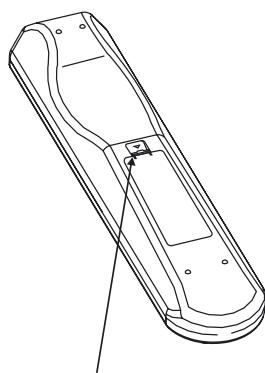
natural_image
Line drawing of a remote control panel with no text or symbolsTRYCK IN OCH LYFT FLIKEN FÖR ATT AVLÄGSNA BATTERILOCKET.

natural_image
Technical line drawing of a remote control device with attached components (no text or symbols)SÄTT I BATTERIERNA. SE TILL ATT DE ÄR RÄTT PLACERADE.
natural_image
Technical line drawing of a mechanical device with no visible text or symbolsSÄTT TILLBAKS BATTERILOCKET GENOM ATT PASSA IN DE TVÅ FLIKARNA I HÅLEN. STÄNG BATTERILOCKET GENOM ATT TRYCKA PÅ DET TILLS DET KLICKAR PÅ PLATS.
SR 6 FJÄRRKONTROLL
natural_image
Line drawing of a remote control device with labeled component '12' (no text or symbols beyond label)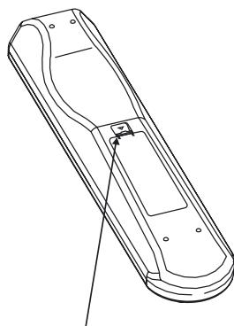
natural_image
Line drawing of a remote control device with no text or symbolsnatural_image
Technical line drawing of a mechanical device with no visible text or symbolsnatural_image
Technical line drawing of a mechanical device with no visible text or symbolswww.NADelectronics.com
©2008 NAD ELECTRONICS INTERNATIONAL
A DIVISION OF LENBROOK INDUSTRIES LIMITED
- NOTE TO CATV SYSTEM INSTALLER
- WARNING
- CAUTION REGARDING PLACEMENT
- IMPORTANT INFORMATION TO UK CUSTOMERS
- IMPORTANT
- IF IN DOUBT CONSULT A COMPETENT ELECTRICIAN.
- NOTES ON ENVIRONMENTAL PROTECTION
- RECORD YOUR MODEL NUMBER (NOW, WHILE YOU CAN SEE IT)
- GETTING STARTED
- UNPACKING AND SETUP
- WHAT'S IN THE BOX
- SAVE THE PACKAGING
- CHOOSING A LOCATION
- NOTES ON INSTALLATION
- DO NOT REMOVE THE COVER, THERE ARE NO USER-SERVICEABLE PARTS INSIDE.
- BARE WIRES AND PIN CONNECTORS
- QUICK START
- NOTE
- FRONT PANEL
- ATTENTION!
- REAR PANEL
- TO MAKE A RECORDING
- TAPE TO TAPE COPYING
- SR 6 REMOTE CONTROL
- CD PLAYER CONTROL (for use with NAD CD Player)
- TUNER CONTROL (for use with NAD AM/FM/DAB Tuner)
- SPECIFICATIONS
- CHOIX D'UN EMPLACEMENT
- TELECOMMANDE SR 6
- MANDO A DISTANCIA SR 6
- TAPE MONITOR IN, OUT (NASTRO MONITOR IN, OUT):
- TELECOMANDO SR 6
- FERNBEDIENUNG SR 6
- WAARSCHUWING M.B.T. PLAATSING
- BEWAAR DE VERPAKKING
- IEC AC MAINS (POWER) INPUT (INGANG
- SR 6 AFSTANDSBEDIENING
- UPPACKNING OCH INSTALLATION VAD FINNS DET I KARTONGEN
- TAPE 2 IN/OUT (IN OCH UTGÅNG FÖR BANDSPELARE 2):
- TAPE MONITOR IN/OUT (IN OCH UTGÅNG FÖR BANDSPELARE
- SR 6 FJÄRRKONTROLL
Brand : NAD
Model : C355BEE
Category : Integrated amplifier