
C372 - Integrated amplifier NAD - Free user manual and instructions
Find the device manual for free C372 NAD in PDF.
| Brand | NAD |
| Model | C372 |
| Product Type | Integrated Stereo Amplifier |
| Output Power (8 ohms) | 2 x 170 W |
| Dynamic Power (8 ohms) | 2 x 220 W |
| Dynamic Power (4 ohms) | 2 x 340 W |
| Total Harmonic Distortion | 0.02 % |
| Intermodulation Distortion | 0.003 % |
| Damping Factor (8 ohms) | > 150 |
| Input Sensitivity | 1.22 V / 20 kΩ / 470 pF |
| Frequency Response (20-20,000 Hz) | ± 0.3 dB |
| Signal-to-Noise Ratio (ref. rated power) | > 120 dB (A-weighted) |
| Signal-to-Noise Ratio (ref. 1 W) | > 100 dB (A-weighted) |
| Remote Control | Yes, SR 5 (supplied) |
| Analog Inputs | Phono, CD, Video, Aux, Tuner, Tape 1/2 |
| Preamp Outputs | 2 pairs (Pre Out 1 & 2) |
| Speaker Outputs | A and B (2 pairs) |
| Bridge Mode | Yes (up to 300 W into 8 ohms) |
| Soft Clipping | Yes (switchable) |
| IR Input/Output | Yes (for control relay) |
| 12 V Trigger Output | Yes (max 200 mA) |
| Switched Auxiliary Mains Outlet | Yes (max 100 W) |
| Power Supply | AC Mains (detachable cord) |
| Standby Consumption | Very low |
| Weight (approximate) | Approximately 12 kg (not exactly specified) |
| Dimensions (W x H x D) | Standard width 435 mm, height approx. 120 mm, depth approx. 300 mm (estimate) |
Frequently Asked Questions - C372 NAD
User questions about C372 NAD
0 question about this device. Answer the ones you know or ask your own.
Ask a new question about this device
Download the instructions for your Integrated amplifier in PDF format for free! Find your manual C372 - NAD and take your electronic device back in hand. On this page are published all the documents necessary for the use of your device. C372 by NAD.
USER MANUAL C372 NAD
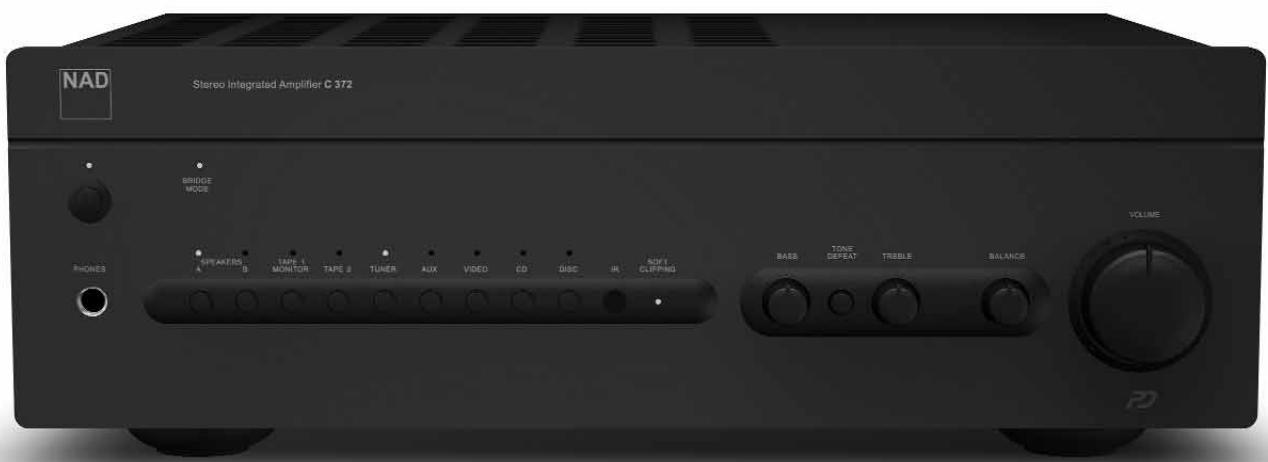
Stereo Integrated Amplifier
Owner's Manual
Warning: To reduce the risk of fire or electric shock, do not expose this unit to rain or moisture.
The lightning flash with an arrowhead symbol within an equilateral triangle, is intended to alert the user to the presence of uninsulated “dangerous voltage” within the product's enclosure that may be of sufficient magnitude to constitute a risk of electric shock to persons.
The exclamation point within an equilateral triangle is intended to alert the user to the presence of important operating and maintenance (servicing) instructions in the literature accompanying the product.
Do not place this unit on an unstable cart, stand or tripod, bracket or table. The unit may fall, causing serious injury to a child or adult and serious damage to the unit. Use only with a cart, stand, tripod, bracket or table recommended by the manufacturer or sold with the unit. Any mounting of the device on a wall or ceiling should follow the manufacturer's instructions and should use a mounting accessory recommended by the manufacturer.
An appliance and cart combination should be moved with care. Quick stops, excessive force and uneven surfaces may cause the appliance and cart combination to overturn.
Read and follow all the safety and operating instructions before connecting or using this unit. Retain this notice and the owner's manual for future reference.
All warnings on the unit and in its operating instructions should be adhered to.
Do not use this unit near water; for example, near a bath tub, washbowl, kitchen sink, laundry tub, in a wet basement or near a swimming pool.
The unit should be installed so that its location or position does not interfere with its proper ventilation. For example, it should not be situated on a bed, sofa, rug or similar surface that may block the ventilation openings; or placed in a built-in installation, such as a bookcase or cabinet, that may impede the flow of air through its ventilation openings.
The unit should be situated from heat sources such as radiators, heat registers, stoves or other devices (including amplifiers) that produce heat.
The unit should be connected to a power supply outlet only of the voltage and frequency marked on its rear panel.
The power supply cord should be routed so that it is not likely to be walked on or pinched, especially near the plug, convenience receptacles, or where the cord exits from the unit.
Unplug the unit from the wall outlet before cleaning. Never use benzine, thinner or other solvents for cleaning. Use only a soft damp cloth.
The power supply cord of the unit should be unplugged from the wall outlet when it is to be unused for a long period of time.
Care should be taken so that objects do not fall, and liquids are not spilled into the enclosure through any openings.
This unit should be serviced by qualified service personnel when:
A. The power cord or the plug has been damaged; or
B. Objects have fallen, or liquid has been spilled into the unit; or
C. The unit has been exposed to rain or liquids of any kind; or
D. The unit does not appear to operate normally or exhibits a marked change in performance; or
E. The device has been dropped or the enclosure damaged.
DO NOT ATTEMPT SERVICING OF THIS UNIT YOURSELF. REFER SERVICING TO QUALIFIED SERVICE PERSONNEL
Upon completion of any servicing or repairs, request the service shop's assurance that only Factory Authorized Replacement Parts with the same characteristics as the original parts have been used, and that the routine safety checks have been performed to guarantee that the equipment is in safe operating condition. REPLACEMENT WITH UNAUTHORIZED PARTS MAY RESULT IN FIRE, ELECTRIC SHOCK OR OTHER HAZARDS.
ATTENTION
POUR ÉVITER LES CHOC ELECTRIQUES, INTRODUIRE LA LAME LA PLUS LARGE DE LA FICHE DANS LA BORNE CORRESPONDANTE DE LA PRISE ET POUSSER JUSQU'AU FOND.
CAUTION
TO PREVENT ELECTRIC SHOCK, MATCH WIDE BLADE OF PLUG TO WIDE SLOT FULLY INSERT.
If an indoor antenna is used (either built into the set or installed separately), never allow any part of the antenna to touch the metal parts of other electrical appliances such as a lamp, TV set etc.
CAUTION POWER LINES
Any outdoor antenna must be located away from all power lines.
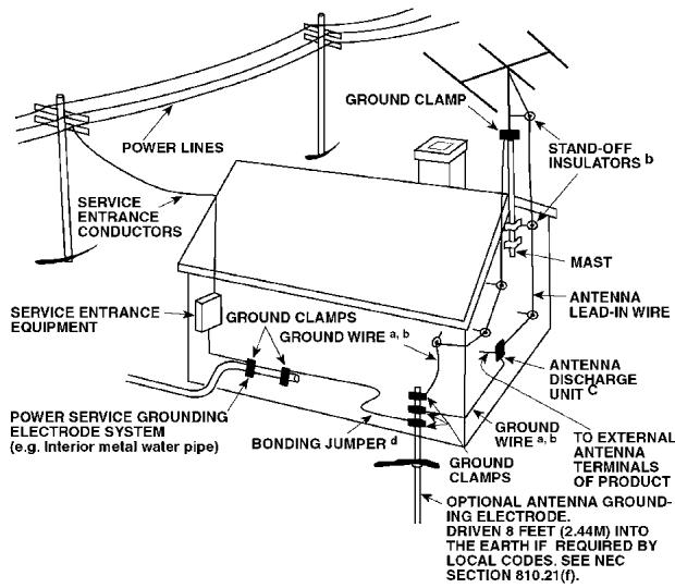
OUTDOOR ANTENNA GROUNDING
If an outside antenna is connected to your tuner or tuner-preamplifier, be sure the antenna system is grounded so as to provide some protection against voltage surges and built-up static charges. Article 810 of the National Electrical Code, ANSI/NFPA No. 70-1984, provides information with respect to proper grounding of the mast and supporting structure, grounding of the lead-in wire to an antenna discharge unit, size of grounding conductors, location of antenna discharge unit, connection to grounding electrodes and requirements for the grounding electrode.
a. Use No. 10 AWG (5.3mm2) copper, No. 8 AWG (8.4mm2) aluminium, No. 17 AWG (1.0mm2) copper-clad steel or bronze wire, or larger, as a ground wire.
b. Secure antenna lead-in and ground wires to house with stand-off insulators spaced from 4-6 feet (1.22 - 1.83 m) apart.
c. Mount antenna discharge unit as close as possible to where lead-in enters house.
d. Use jumper wire not smaller than No.6 AWG (13.3mm2) copper, or the equivalent, when a separate antenna-grounding electrode is used. see NEC Section 810-21 (j).
EXAMPLE OF ANTENNA GROUNDING AS PER NATIONAL ELECTRICAL CODE INSTRUCTIONS CONTAINED IN ARTICLE 810 - RADIO AND TELEVISION EQUIPMENT.
NOTE TO CATV SYSTEM INSTALLER: This reminder is provided to call the CATV system installer's attention to Article 820-40 of the National Electrical Code that provides guidelines for proper grounding and, in particular, specifies that the ground cable ground shall be connected to the grounding system of the building, as close to the point of cable entry as practical.
FRONT PANEL CONTROLS
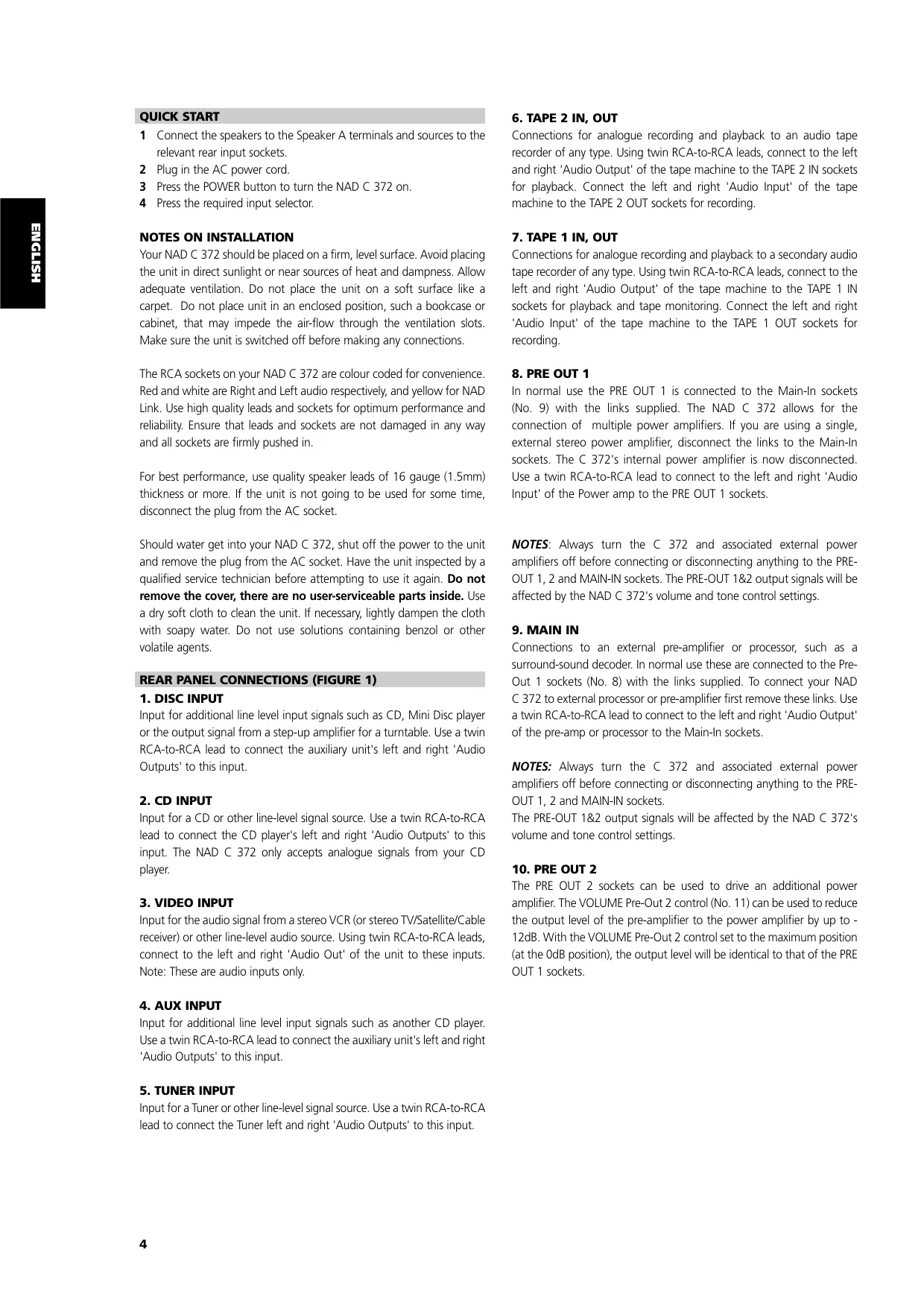
QUICK START
1 Connect the speakers to the Speaker A terminals and sources to the relevant rear input sockets.
2 Plug in the AC power cord.
3 Press the POWER button to turn the NAD C 372 on.
4 Press the required input selector.
NOTES ON INSTALLATION
Your NAD C 372 should be placed on a firm, level surface. Avoid placing the unit in direct sunlight or near sources of heat and dampness. Allow adequate ventilation. Do not place the unit on a soft surface like a carpet. Do not place unit in an enclosed position, such a bookcase or cabinet, that may impede the air-flow through the ventilation slots. Make sure the unit is switched off before making any connections.
The RCA sockets on your NAD C 372 are colour coded for convenience. Red and white are Right and Left audio respectively, and yellow for NAD Link. Use high quality leads and sockets for optimum performance and reliability. Ensure that leads and sockets are not damaged in any way and all sockets are firmly pushed in.
For best performance, use quality speaker leads of 16 gauge (1.5mm) thickness or more. If the unit is not going to be used for some time, disconnect the plug from the AC socket.
Should water get into your NAD C 372, shut off the power to the unit and remove the plug from the AC socket. Have the unit inspected by a qualified service technician before attempting to use it again. Do not remove the cover, there are no user-serviceable parts inside. Use a dry soft cloth to clean the unit. If necessary, lightly dampen the cloth with soapy water. Do not use solutions containing benzol or other volatile agents.
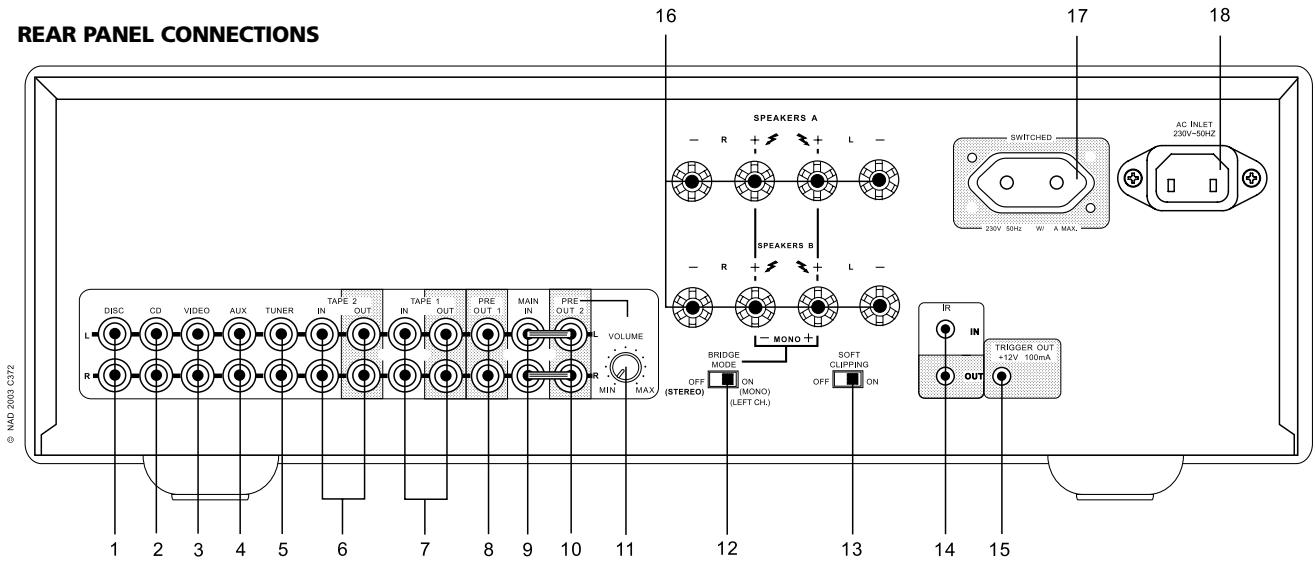
REAR PANEL CONNECTIONS (FIGURE 1)
1. DISC INPUT
Input for additional line level input signals such as CD, Mini Disc player or the output signal from a step-up amplifier for a turntable. Use a twin RCA-to-RCA lead to connect the auxiliary unit's left and right 'Audio Outputs' to this input.
2. CD INPUT
Input for a CD or other line-level signal source. Use a twin RCA-to-RCA lead to connect the CD player's left and right 'Audio Outputs' to this input. The NAD C 372 only accepts analogue signals from your CD player.
3. VIDEO INPUT
Input for the audio signal from a stereo VCR (or stereo TV/Satellite/Cable receiver) or other line-level audio source. Using twin RCA-to-RCA leads, connect to the left and right 'Audio Out' of the unit to these inputs. Note: These are audio inputs only.
4. AUX INPUT
Input for additional line level input signals such as another CD player. Use a twin RCA-to-RCA lead to connect the auxiliary unit's left and right 'Audio Outputs' to this input.
5. TUNER INPUT
Input for a Tuner or other line-level signal source. Use a twin RCA-to-RCA lead to connect the Tuner left and right 'Audio Outputs' to this input.
6. TAPE 2 IN, OUT
Connections for analogue recording and playback to an audio tape recorder of any type. Using twin RCA-to-RCA leads, connect to the left and right 'Audio Output' of the tape machine to the TAPE 2 IN sockets for playback. Connect the left and right 'Audio Input' of the tape machine to the TAPE 2 OUT sockets for recording.
7. TAPE 1 IN, OUT
Connections for analogue recording and playback to a secondary audio tape recorder of any type. Using twin RCA-to-RCA leads, connect to the left and right 'Audio Output' of the tape machine to the TAPE 1 IN sockets for playback and tape monitoring. Connect the left and right 'Audio Input' of the tape machine to the TAPE 1 OUT sockets for recording.
8. PRE OUT 1
In normal use the PRE OUT 1 is connected to the Main-In sockets (No. 9) with the links supplied. The NAD C 372 allows for the connection of multiple power amplifiers. If you are using a single, external stereo power amplifier, disconnect the links to the Main-In sockets. The C 372's internal power amplifier is now disconnected. Use a twin RCA-to-RCA lead to connect to the left and right 'Audio Input' of the Power amp to the PRE OUT 1 sockets.
NOTES: Always turn the C 372 and associated external power amplifiers off before connecting or disconnecting anything to the PRE-OUT 1, 2 and MAIN-IN sockets. The PRE-OUT 1&2 output signals will be affected by the NAD C 372's volume and tone control settings.
9. MAIN IN
Connections to an external pre-amplifier or processor, such as a surround-sound decoder. In normal use these are connected to the Pre-Out 1 sockets (No. 8) with the links supplied. To connect your NAD C 372 to external processor or pre-amplifier first remove these links. Use a twin RCA-to-RCA lead to connect to the left and right 'Audio Output' of the pre-amp or processor to the Main-In sockets.
NOTES: Always turn the C 372 and associated external power amplifiers off before connecting or disconnecting anything to the PRE-OUT 1, 2 and MAIN-IN sockets.
The PRE-OUT 1&2 output signals will be affected by the NAD C 372's volume and tone control settings.
10. PRE OUT 2
The PRE OUT 2 sockets can be used to drive an additional power amplifier. The VOLUME Pre-Out 2 control (No. 11) can be used to reduce the output level of the pre-amplifier to the power amplifier by up to -12dB. With the VOLUME Pre-Out 2 control set to the maximum position (at the 0dB position), the output level will be identical to that of the PRE OUT 1 sockets.
If you are using a pair of power amplifiers specifically for Bi-Amping, use the PRE OUT 2 sockets to connect the power amplifier with the highest gain of the pair. By adjusting the VOLUME PRE OUT 2 control (No. 11) the volume level can be matched exactly to that of the power amplifier connected to the PRE OUT 1 sockets. Refer also to chapter "Bi-Amping" for more information. Use a twin RCA-to-RCA lead to connect to the left and right 'Audio Input' of the Power amp to the PRE OUT 1 & 2 sockets.
NOTES: Always turn the C 372 and associated external power amplifiers off before connecting or disconnecting anything to the PRE-OUT 1, 2 and MAIN-IN sockets.
The PRE-OUT 1&2 output signals will be affected by the NAD C 372's volume and tone control settings.
11. VOLUME PRE OUT 2
The VOLUME Pre-Out 2 control allows for adjustment of the output level of the PRE OUT 2 sockets. The output level can be reduced from 0dB to -12dB; when set to the maximum position (at the 0dB position), the output level will be identical to that of the PRE OUT 1 sockets. Refer also to chapter "Bi-Amping" for more information.
NOTES: Always turn the C 372 and associated external power amplifiers off before connecting or disconnecting anything to the PRE-OUT 1, 2 and MAIN-IN sockets.
The PRE-OUT 1&2 output signals will be affected by the NAD C 372's volume and tone control settings.
12. BRIDGE MODE
The NAD C 372 can be used as part of a higher power stereo or home-theatre system, by connecting adding additional power amplifiers. If the power amp section in the NAD C 372 is to be used to drive a single speaker, then use the Bridge switch to run the built-in Left and Right power amplifiers as a single channel, high power unit. Set the BRIDGE MODE switch to the 'Bridge' position and connect the speaker to the terminals marked 'L+' and 'R+' ensuring that the 'L+' is connected to the '+' terminal on your loudspeaker and the 'R+' is connected to the loudspeaker's '-' terminal. Connect the source to the Left MAIN-IN input.
In Bridged Mode the NAD C 372 will produce approximately 300W into an 8 ohm loudspeaker. In this mode, the amplifier sections will react as though the speaker impedance has been halved. Low impedance speakers (under 8 ohms) are not recommended when using Bridge Mode, as these may cause the amplifier's thermal cut-out to operate if played at high levels.
The Bridge LED on the front panel (Fig. 2; No. 2) will illuminate when the amplifier is in Bridge mode.
NOTES: Do not connect anything to the Right MAIN-IN input (No. 9) when Bridge Mode is selected. Always turn the C 372 and associated external power amplifiers off before connecting or disconnecting anything to the PRE-OUT 1, 2 and MAIN-IN sockets.
13. SOFT CLIPPING™
When an amplifier is driven beyond its specified power output, a hard, distorted sound can be heard on very loud sounds. This is caused by the amplifier cutting off or 'hard clipping' the peaks of sound that it was not designed to reproduce. The NAD Soft Clipping™ circuit gently limits the output of the system to minimise audible distortion if the amplifier is overdriven.
If your listening involves moderate power levels you may leave the Soft Clipping™ switch to Off. If you are likely to play at high levels, that could stretch the amplifier's power capability, then switch Soft Clipping On. The Soft Clipping™ indicator on the front panel will illuminate when the amplifier is in Soft Clipping mode.
14. IR IN, OUT
The IR IN/OUT connector is used to pass commands from other units fitted with IR IN/OUT connectors. This allows centralized control of a complete system, and also allows some of the basic functions of other NAD components (such as a tuner, CD player or cassette-deck) also equipped with IR IN/OUT to be controlled with the amplifier's remote control. To function with such other units, connect the C 372's IR OUT to the IR IN on the other unit. The IR connectors can be daisy-chained, IN to OUT, so that a whole system can be controlled from the remote control facilities of one unit.
NOTES: It is advisable not to connect IR IN/OUT if these units that have their own built-in remote control command receiver and are positioned together, in direct view from the remote control handset. If you are unsure, try operating the products without IR IN/OUT first; If the unit responds to the remote control command, it will not be necessary to connect IR IN/OUT. Never loop the last unit back to the first NAD unit in the IR IN/OUT chain. Unplug all units from the mains before connecting or disconnecting IR IN/OUT.
15. 12V TRIGGER OUT
This output allows to remotely switch on or off ancillary equipment such as a tuner, power amplifier, etc. which are also equipped with a 12V trigger input. This can also be an AC outlet power strip equipped with a 12V trigger input. The 12V trigger output is activated whenever the unit is switched to normal operational mode from Stand-by or Off.
For switching Stand-by/Power On of an external component through the C 372, connect the12V-trigger output of the C 372 to the remote component's DC input jack. The plug required is a standard 3.5mm Mini-Jack plug ("mono"): The tip is the live or + connection, the shaft of the input jack is the 12V-trigger - or ground connection.
NOTES: Check the specifications of the Trigger input terminal on the other components to ensure these are compatible with the C 372's 12V-trigger output. NAD components equipped with 12V input triggers are fully compatible with the C 372's 12V output trigger. The C 372's 12V-trigger output voltage is 12V DC. The total maximum current must not exceed 200mA. Typically, NAD 12V input triggers draw less than 10mA of current.
Before making any connections to any 12V trigger input or output, make sure all components are disconnected from the AC mains.
Failure to observe the above may result in damage to the C 372 or any ancillary components attached to it. If in doubt over the connections, installation and operation of the 12V trigger output consult your NAD dealer.
16. SPEAKERS A + SPEAKERS B
The NAD C 372 is equipped with two sets of speaker connectors. Use the Speakers A connectors for the 'main' speakers and use the Speakers B connectors for a second pair, for example, extension speakers located in another room.
Under normal operation, connect the right speaker to the terminals market 'R+' and 'R-' ensuring that the 'R+' is connected to the '+' terminal on your loudspeaker and the 'R-' is connected to the loudspeaker's '-' terminal. Connect the terminals marked 'L+' and 'L-' to the left speaker in the same way.
In Bridge Mode, connect the single speaker to the terminals marked 'R+' and 'L+' ensuring that the 'L+' is connected to the '+' terminal on your loudspeaker and the 'L+' is connected to the loudspeaker's '-' terminal. Refer also to section "Bridging" in this chapter (No. 12).
Always use heavy duty (16 gauge; 1.5mm, or thicker) stranded wire to connect loudspeakers to your NAD C 372. The high-current binding post terminals can be used as a screw terminal for cables terminating in spade or pin sockets or for cables with bare wire ends.
BARE WIRES AND PIN CONNECTORS
Bare wires and pin sockets should be inserted into the hole in the shaft of the terminal. Unscrew the speaker terminal's plastic bushing until the hole in the screw shaft is revealed. Insert the pin or bare cable end into the hole and secure the cable by tightening down the terminal's bushing. Ensure bare wire from the speaker cables does not touch the back panel or another socket. Ensure that there is only 1/2" (1cm) of bare cable or pin and no loose strands of speakers wire.
NOTE: Make sure the speaker impedance is 4 ohms or more when connecting only one pair of speakers; make sure the speaker impedance for all speakers is more then 8 ohms when connecting two sets of speakers. In Bridge Mode, the impedance of the loudspeaker should also be 8 ohms or higher.
17. SWITCHED AC OUTLET
The AC power cord of another component may be plugged into this accessory outlet. Components plugged into this outlet will be switched On and Off by the POWER button on the front panel or by the ON and STAND-BY button on the remote control handset.
NOTE: The total power consumption of any components connected to the AC outlets may not exceed 100 Watts.
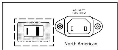
18. IEC AC MAINS (POWER) INPUT
The C 372 comes supplied with a separate AC Mains cable. Before connecting the cable to a live wall socket ensure that it is firmly connected to the NAD C 372's AC Mains input socket first. Always disconnect the AC Mains cable plug from the live wall socket first, before disconnecting the cable from the C 372 Mains input socket.
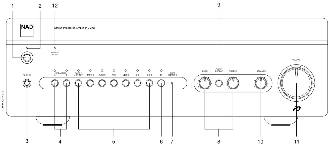
FRONT PANEL CONTROLS (FIGURE 2)
1. POWER ON/OFF
Press the POWER button to switch the amplifier On. The Stand-by indicator (No. 2) over the power button will light up amber and after a short pause will turn to green to indicate the amplifier is now ready for normal operation.
Pressing the POWER switch again will turn the unit OFF completely, it will not respond to the remote control.
REMOTE CONTROL (FIGURE 3) ON AND OFF BUTTONS
Press the POWER button to switch the amplifier On. The Stand-by indicator (No. 2) over the power button will light up amber. Pressing the POWER switch again will turn the unit OFF completely, it will not respond to the remote control. The NAD C 372 remote has a separate On and Off button. This can be particularly useful to keep components within a system "in sync": This way all components will switch to standby when Off is pressed or switch to operating mode when On is pressed, instead of some components switching On when the amplifier is switched to Stand-by. (Note that the other components have to be capable of responding to the separate On and Off commands as well). Press the ON button to switch the unit from Stand-by to the operating mode; The Stand-by indicator (Fig. 2; No. 2) will turn from amber to red, then to green and the indicator for the last selected input will blink and light up. Press the OFF button to switch the unit to the Stand-by mode: The Stand-by indicator will light up amber.
NOTE: In Stand-by mode the C 372 uses very little power. However, it is recommended that you switch the unit totally off if it is not going to be used for more than a couple of days. Switch off completely by pressing the POWER button on the front panel (No. 1), all lights will extinguish.
2. POWER / STAND-BY / PROTECTION INDICATOR
Upon switching the power on, the LED will light up amber in standby state. While one of the input select buttons is pressed, the LED will turn red for a moment, then turn green for ON state. In cases of serious abuse of the amplifier, such as overheating, excessively low loudspeaker impedance, short circuit etc. the amplifier will engage its Protection circuitry, indicated by the LED turning from green to red, and the sound being muted. In such a case, turn the amplifier off, wait for it to cool down and/or check the speaker connections, making sure the overall loudspeaker impedance doesn't go below 4 ohms. Once the cause for the protection circuitry to engage has been removed, press Power again to resume normal operation.
The diagram below shows the operation of the Stand-by / protection
| Green | Amber | Red | |
| Normal Operation | ● | ||
| Stand-by | ● | ||
| Protection | ● |
indicator:
3. HEADPHONE SOCKET
A 1/4" stereo jack socket is supplied for headphone listening and will work with conventional headphones of any impedance. The headphone socket will work in parallel to the selected speakers. To listen to headphones only, de-select Speakers A and/or B (No. 4).
The volume, tone and balance controls are operative for headphone listening. Use a suitable adapter to connect headphones with other types of sockets, such as 3.5mm stereo 'personal stereo' jack plugs.
NOTE: Make certain that the volume control is turned to minimum (fully counter-clockwise) before connecting or disconnecting headphones. Listening at high levels can damage your hearing.
4. SPEAKERS A & B
The Speakers A and B buttons engage or disengage the speakers connected respectively to the Speakers A and Speakers B terminals on the rear panel. Press A to switch the speakers connected to the speaker A terminals On or Off. Press B to switch the speakers connected to the speaker A terminals On or Off. The indicator directly over the buttons shows the status of speakers A and B.
If Speakers A and B are both engaged (both indicators over the Speakers A and B buttons are lit), the amplifier's output power is fed to both sets of speakers in parallel. If speakers A and B are disengaged, both sets of speakers are silenced. You can use this setting mode to listen to headphones (No. 3).
NOTES: Always turn the volume down when engaging or disengaging either Speaker A or Speaker B. When using Speakers A and B at the same time, make sure that the total impedance of the speakers connected is more than 8 ohms. Refer to the table below:
| Bridge Mode | Stereo Mode |
| One speaker 8Ω minimum | One speaker 4Ω minimum |
| Two speakers 16Ω minimum | Two speakers 8Ω minimum |
5. INPUT SELECTORS
These buttons select the active input to the NAD C 372 and the signal sent to the loudspeakers, the Tape outputs and the Pre-Out sockets. The buttons on the remote control handset duplicate these buttons, with the exception of the tuner input; see below. Green indicators just above each button show which input is currently selected.
DISC Selects a line-level source connected to the DISC sockets as the active input.
CD Selects the CD (or other line-level source) connected to the CD sockets, as the active input.
VIDEO Selects the VCR (or stereo TV/Satellite/Cable receiver) connected to the VIDEO sockets, as the active input.
AUX Selects a line-level source connected to the AUX sockets, as the active input.
TUNER Selects the tuner (or other line-level source) connected to the Tuner sockets, as the active input.
TAPE 2 Selects Tape 2 as the active input.
TAPE 1 Monitor Selects the output from a tape recorder when playing back tapes or monitoring recordings being made through the Tape 1 sockets. Press the Tape 1 button once to select it and again to return to the normal input selection.
Tape 1 is a tape Monitor function which does not override the current input selection. For example, if the CD is the active input when TAPE 1 is selected, then the CD signal will continue to be selected and sent to both the TAPE 2, and TAPE 1 OUTPUT sockets, but it is the sound from recorder connected to Tape 1 that will be heard on the loudspeakers. Apart from the amber indicator to show Tape 1 is engaged, the green indicator for the active input will also stay lit.
NOTE: The remote control handset with the C 372 supplied is of a universal NAD type, designed to operate several NAD models. Some buttons on this handset are inoperative as the functions aren't supported by the C 372. The Video 2 and Video 3 input selector buttons on the remote control handset are inoperative in the case of the C 372.
6. INFRA-RED REMOTE CONTROL COMMAND RECEIVER
The infrared sensor, located behind this circular window, receives commands from the remote control. There must be a clear line-of-sight path from the remote control to this window; if that path is obstructed, the remote control may not work.
NOTES: When a command from the remote control is received, the Stand-by/protection indicator will blink. Note that the indicator may also blink when receiving commands not necessarily for the C 372 but for other components in the system.
Direct sunlight, very bright or fluorescent ambient lighting may affect the operating range and angle for the remote control handset.
7. SOFT CLIPPING™ INDICATOR
The green SOFT CLIPPING™ indicator shows that the Soft Clipping™ mode is engaged. Refer also to chapter "Rear Panel Connections", section 13; "Soft Clipping™" for more information.
8. BASS & TREBLE CONTROLS
The NAD C 372 is fitted with BASS and TREBLE tone controls to adjust the tonal balance of your system.
The 12 o'clock position is 'flat' with no boost or cut and a detent indicates this position. Rotate the control clockwise to increase the amount of Bass or Treble. Rotate the control counter-clockwise to decrease the amount of Bass or Treble. The Tone controls do not affect recordings made using the Tape outputs but will affect the signal going to the Pre-amp outputs (Pre-Out 1 & 2).
9. TONE DEFEAT
The TONE DEFEAT switch bypasses the tone control section of the NAD C 372. If the Tone Controls are not normally used and left in the 12 o'clock position, then it is advisable to switch out the Tone Control section altogether by using this switch. In the 'out' position, the Tone Control circuits are active, pushing the TONE DEFEAT switch 'in' bypasses the Tone Control section.
10. BALANCE
The BALANCE control adjusts the relative levels of the left and right speakers. The 12 o'clock position provides equal level to the left and right channels. A detent indicates this position.
Rotating the control clockwise moves the balance towards the right. Rotating the control counter-clockwise moves the balance to the left. The BALANCE control does not affect recordings made using the Tape outputs but will affect the signal going to the Pre-amp outputs (Pre-Out 1 & 2).
11. VOLUME
The VOLUME control adjusts the overall loudness of the signals being fed to the loudspeakers. It is motor driven and can be adjusted from the remote control handset. The VOLUME control does not affect recordings made using the Tape outputs but will affect the signal going to the Pre-amp outputs (Pre-Out 1 &2).
12. BRIDGE MODE INDICATOR
The BRIDE MODE indicator lights up (amber) when the C 372 is switched to Bridge Mode. Refer also to chapter "Rear Panel Connections", section 12, "Bridge Mode" for more information.
RECORDING
TO MAKE A RECORDING
When any source is selected, its signal is also fed directly to any tape machine connected to the TAPE 2 or TAPE 1 OUTPUTS for recording.
TAPE TO TAPE COPYING
You can copy between two tape machines connected to your NAD C 372. Put the source tape in the recorder connected to Tape 2 and the blank tape into the recorder connected to Tape 1. By selecting TAPE 2 Input you can now record from Tape 2 to Tape 1 and monitor the signal coming from the original tape.
BI-AMPING
Some loudspeakers have separate connection terminals for the LF (Low Frequency) and HF (High Frequency) sections of the speaker. This facility allows to "Bi-Amp" these speakers, where a separate power amplifier is used for the LF and HF section, which may improve overall sound quality.
The NAD C 372 provides two sets of pre-amplifier outputs (PRE OUT 1 & 2) to facilitate the connections for Bi-Amping. Moreover, the level from PRE OUT 2 can be reduced in relation to PRE OUT 1 to accommodate power amplifiers with different gain (amplification factor).
To set up the C 372 with power amplifiers first decide which power amplifier has the highest gain. This is easily done by comparing the loudness level of the power amplifiers in an identical system (keep the volume control at the same level; use the same source and speakers). The amplifier that plays louder has the highest gain (note that this does not need to be the more powerful amplifier of the two). Connect the amplifier with highest gain to the PRE OUT 2 (No. 10) sockets; the other power amplifier to the PRE OUT 1 (No. 8) sockets. From the maximum level position (0dB), use the VOLUME PRE OUT 2 control (No. 11) to reduce the output level of PRE OUT 2 so that the volume level of both power amplifiers is exactly matched.
NOTES: The gain of the NAD C 272 power amplifier is identical to that of the C 372's built-in power amplifier (in fact, the C 272 and C 372's power amplifier section are almost identical). When combined with the NAD C 272 for Bi-Amping, leave the PRE-OUT 1 connected, with the links provided, to MAIN-IN. Connect the C 272 to the PRE-OUT 2 output. Set the VOLUME PRE-OUT 2 control to its maximum position.
The provided links to connect from PRE-OUT 1 to MAIN-IN can also be used to connect from PRE-OUT 2 to MAIN-IN, should the C 372's power amplifier have the highest gain. Always turn the C 372 and external power amplifiers off before connecting or disconnecting anything from Pre-Out and to Main-In sockets.
POWERDRIVE
To meet the diverse requirements of high current drive and high dynamic power, our patented PowerDrive amplifier circuit will build further on our reputation for amazingly effective power. By adding a second high-voltage rail to our well regulated high-current power supply, we get an "overdrive" that can nearly double the continuous power on a short term dynamic power basis. This is a further development and refinement of our renowned Power Envelope circuit, utilized by NAD in the 80's and 90's. PowerDrive differs from Power Envelope in that it offers greater amplifier stability and low impedance drive capability, resulting in less distortion when driving real speakers with real program material.
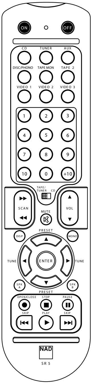
REMOTE CONTROL HANDSET (FIGURE 3)
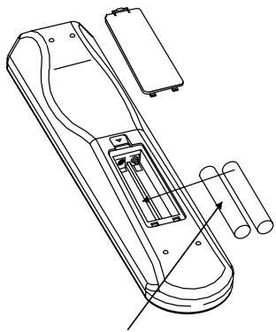
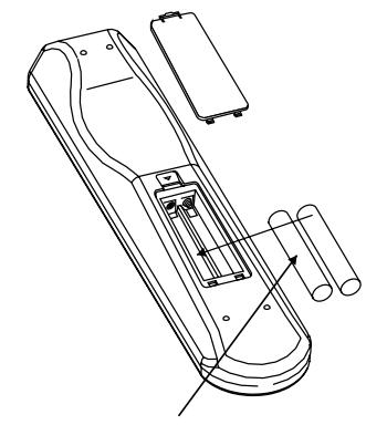
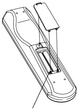
The Remote Control handset handles all the key functions of the NAD C 372 and has additional controls to remotely operate NAD Tuners, Cassette and CD machines. It will operate up to a distance of 16ft (5m). Alkaline batteries are recommended for maximum operating life. Four AAA (R 03) batteries should be fitted in the battery compartment at the back of the Remote Control handset. When replacing batteries, check that they have been put in the right way round, as indicated on the base of the battery compartment. Please refer to previous sections of the manual for a full description of individual functions.
When a command from the remote control is received, the Standby/protection indicator will blink. Note that the indicator may also blink when receiving commands not necessarily for the C 372 but for other components in the system.
POWER ON AND OFF BUTTONS
The NAD C 372 remote has a separate On and Off button. This can be particularly useful to keep components within a system "in sync": This way all components will switch to stand-by when Off is pressed or switch to operating mode when On is pressed, instead of some components switching On when the amplifier is switched to Stand-by. (Note that the other components have to be capable of responding to the separate On and Off commands as well). Press the ON button to switch the unit from Stand-by to the operating mode; The Stand-by indicator (Fig. 2; No. 2) will turn from amber, to red, then to green and the indicator for the last selected input will blink and light up. Press the OFF button to switch the unit to the Stand-by mode: The Stand-by indicator will light up amber.
SPEAKERS A & B
These buttons perform the same function as those on the front panel. The Speakers A and B buttons engage or disengage the speakers connected to respectively the Speakers A and Speakers B terminals on the rear panel. Press A to switch the speakers connected to the speaker A terminals On or Off. Press B to switch the speakers connected to the speaker B terminals On or Off. The indicator directly over the buttons shows the status of speakers A and B.
MUTE
Press the MUTE Button to temporarily switch off the sound to the speakers and headphones. Mute mode is indicated by the active input indicator on the front panel flashing. Press MUTE again to restore sound. Mute does not affect recordings made using the Tape outputs but will affect the signal going to the Preamp outputs (Pre-Out 1 &2).
INPUTS
The input selector buttons perform the same functions as the buttons labelled the same on the front panel.
MASTER VOLUME
Press the MASTER VOLUME ▲ or ▼ buttons to respectively increase or decrease the loudness level. Release the button when the desired level is reached. The motorised Volume Control on the front panel will indicate the level set. The Master Volume buttons do not affect recordings made using the Tape outputs but will affect the signal going to the Pre-amp outputs (Pre-Out 1 &2).
TUNER CONTROL
(for use with NAD Tuner)
TUNE ▲ or ▼ scans respectively higher or lower station frequencies for both AM and FM.
PRESET ▶ or ◀ selects respectively higher or lower number station preset.
CD PLAYER CONTROL
(for use with NAD CD/DVD Player)
II engages Pause
engages Stop
▶ engages Play, toggles between Play and Pause or engages Track skip; Press once to respectively go to the next track or to return to start of current or previous track.
● engages CD drawer Open/Close; Press once to open the CD drawer then once again to close the CD drawer and start playback.
The TAPE/TUNER - CD switch applies tape controls to the transport keys when in the TAPE/TUNER position, and applies CD controls to the transport keys when in the CD position.
CASSETTE DECK CONTROL
(for use with single NAD Cassette Decks)
▶ engages Forward Play.
- Press to put cassette deck into record-pause. Press Play to start recording.
■ Stops Play or Recording.
◀◀ ◀◀ engages Rewind.
▶▶ ▶▶| engages Fast Forward.
The TAPE/TUNER - CD switch applies tape controls to the transport keys when in the TAPE/TUNER position, and applies CD controls to the transport keys when in the CD position.
NOTES: The remote control handset supplied with the C 372 is of a universal NAD type, designed to operate several NAD models. Some buttons on this handset are inoperative as the functions aren't supported by the C 372. The Video 2 and Video 3 input selector buttons (inside section No. 2) on the remote control handset are inoperative in the case of the C 372.
Direct sunlight or very bright ambient lighting may affect the operating range and angle for the remote control handset.
REMOTE CONTROL (FIGURE 3)
natural_image
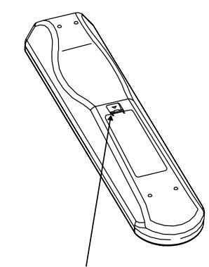
Line drawing of a remote control casing with mounting holes and a handle (no text or symbols)PRESS IN AND LIFT TAB TO REMOVE BATTERY COVER OUT OF RECESS
natural_image
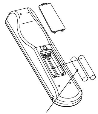
Technical line drawing of a handheld device with internal components and external housing (no text or symbols)PLACE BATTERIES INTO OPENING. ENSURE THE CORRECT FITTING IS OBSERVED
natural_image
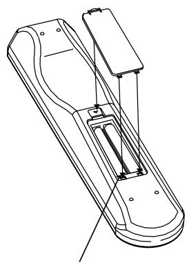
Technical line drawing of a mechanical device with no visible text or symbolsREPLACE BATTERY COVER BY ALIGNING AND INSERTING THE TWO TABS INTO THE HOLES.

natural_image
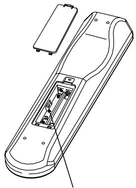
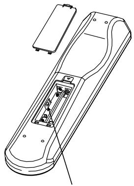
Technical line drawing of a remote control box with internal components (no text or symbols)DEV.1 & DEV.2
PRESS BATTERY COVER INTO PLACE UNTIL IT 'CLICKS' CLOSED
| TROUBLESHOOTING | ||
| Problem | Cause | Solution |
| NO SOUND | Power AC lead unplugged or power not switched onTape 1 Monitor selectedMute onRear Pre-out/Main-in amp links not fittedNo speakers selected | Check if AC lead is plugged in and power switched onDe-select Tape 1 Monitor modeSwitch off MuteFit linksSelect the appropriate speakers (A / B) |
| NO SOUND ONE CHANNEL | Balance control not centredSpeaker not properly connected or damaged.Input lead disconnected or damaged | Centre Balance controlCheck connections and speakersCheck leads and connections |
| WEAK BASS /DIFFUSE OR NO STEREO IMAGE | Speakers wired out of phaseBridge Mode selected when speakers are connected normally | Check connections to all speakers in the systemDisengage Bridge Mode |
| REMOTE CONTROL HANDSET NOT WORKING | Batteries flat, or incorrectly insertedIR transmitter or receiver windows obstructedIR receiver in direct sun or very bright ambient light | Check or replace batteriesRemove obstructionPlace unit away from direct sun, reduce amount of ambient light |
| POWER/PROTECTION LED STAYS RED UPON TURNING POWER ON | Loudspeakers cabling has a short-circuit | Turn amplifier off and check loudspeaker cable connections for both speakers at amplifier's back panel and loudspeakers. Turn amplifier on. |
| POWER/PROTECTION INDICATOR TURNS RED DURING OPERATION | Amplifier has over-heated.Overall impedance of loudspeakers too low | Turn amplifier off. Make sure ventilation slots on top and bottom of amplifier aren't blocked.After amplifier has cooled down, turn back on.Ensure the overall loudspeaker impedance isn't below 4 ohms.Check loudspeaker cables for short circuits |
SPECIFICATIONS
AMPLIFIER SECTION
Power output Stereo Mode 2 x 170W
(8 ohms within rated distortion)
IHF dynamic power; 8 ohms 2 x 220W
IHF dynamic power; 4 ohms 2 x 340W
Total harmonic distortion at rated power 0.02%
IM distortion at rated power 0.003%
Damping factor 8 ohms >150
Input sensitivity and impedance 1.22 V / 20k ohms/470 pF
Frequency response 20 to 20,000 Hz ±0.3dB
Signal/noise ratio; ref rated power / 8 ohms (A-WTD) >120dB
Signal/noise ratio; ref 1W / 8 ohms (A-WTD) >100dB
Remote Control Yes, SR 5
Specifications are subject to change without notice.
For the latest information about your C 372, updated documentation and features please log onto www.nadelectronics.com
MISE EN ROUTE RAPIDE
6. ENTREE / SORTIE "MAGNETOPHONE 2" [TAPE 2 IN, OUT]
7. ENTREE / SORTIE "MAGNETOPHONE 1" [TAPE 1 IN, OUT]
1. "MARCHE / ARRET" [POWER ON/OFF]
3. PRISE "CASQUE" [HEADPHONE]
"COPIER ENTRE CASSETTES" [TAPE TO TAPE]
natural_image
Line drawing of a remote control device with no text or symbolsENFONCEZ ET RELEVEZ LA LANGUETTE POUR RETIRER LE COUVERCLE DU COMPARTIMENT DES PILES
![NAD C372 - "COPIER ENTRE CASSETTES" [TAPE TO TAPE] - 1](/content/2024/12/96921/images/13924c3a776d55ecf8743fca05f0ba5cb7f746d39a0f6b2272392b0a2ba645cd.jpg)
natural_image
Technical line drawing of a handheld device with internal components and external casing (no text or symbols)INSÉREZ LES PILES DANS LE COMPARTIMENT. VÉRIFIEZ LA BONNE MISE EN PLACE
![NAD C372 - "COPIER ENTRE CASSETTES" [TAPE TO TAPE] - 2](/content/2024/12/96921/images/597d7dda19afbac8ee1a85eebbf4cf6a595b746c138e1ac1d1a3842b7abd65cb.jpg)
natural_image
Technical line drawing of a mechanical device with no visible text or symbolsREMETTEZ EN PLACE LE COUVERCLE DU COMPARTIMENT DES PILES EN ALIGNENT LES DEUX LANGUETTES AVEC LES TROUS, PUIS EN LES Y INSÉRANT.
![NAD C372 - "COPIER ENTRE CASSETTES" [TAPE TO TAPE] - 3](/content/2024/12/96921/images/45265d5823ded9dd1e87ea07ff48f9c06ded1b915d2c2bf35c1cfe633e254ca5.jpg)
natural_image
Technical line drawing of a remote control box with internal components (no text or symbols)DEV.1 & DEV.2
APPUYEZ SUR LE COUVERCLE DU COMPARTIMENT DES PILES POUR LE METTRE UN PLACE (VOUS RESSENTIREZ UN DÉCLIC)
CARACTÉRISTIQUES
SECTION AMPLIFICATEUR
3. KOPFHÖRERBUCHSE (HEADPHONE)
natural_image
Line drawing of a remote control device with a handle and mounting bracket (no text or symbols)HINEINDRÜCKEN UND ZUM ABNEHMEN DES BATTERIEFACHDECKELS LASCHE ANHEBEN.
natural_image
Technical line drawing of a mechanical device with internal components and mounting holes (no text or symbols)natural_image
Technical line drawing of a mechanical device with internal components and mounting brackets (no text or symbols)BATTERIEFACHDECKEL DURCH
AUSRICHTEN UND EINFÜHREN IN DIE
AUSSPARUNGEN WIEDER EINSETZEN.
BATTERIEFACHDECKEL
HINEINDRÜCKEN BIS ER MIT EINEM
HÖRBAREN KLICK SCHLIESST.
natural_image
Technical line drawing of a remote control device with internal components (no text or symbols)DEV.1 & DEV.2
SNELSTART
6. TAPE 2 IN, OUT [CASSETTERECORDER 2 IN, UIT]
7. TAPE 1 IN, OUT [CASSETTERECORDER 1 IN, UIT]
14. IR IN, OUT [IR IN, UIT]
AFSTANDSBEDIENING (AFBEELDING 3) ON/OFF [TOETSEN AAN / UIT]
natural_image
Line drawing of a mobile phone casing with a handle and ventilation slots (no text or symbols)HET LIPJE INDRUKKEN EN OPHEFFEN OM HET BATTERIJDEKSEL UIT DE ZITTING TE VERWIJDEREN
![NAD C372 - AFSTANDSBEDIENING (AFBEELDING 3) ON/OFF [TOETSEN AAN / UIT] - 1](/content/2024/12/96921/images/c75a26e1722b2f178a858f9b2c42f0b34f04198625bfa4ef463cc76fc6e68842.jpg)
natural_image
Technical line drawing of a mechanical device with no visible text or symbolsSTEEK DE BATTERIJEN IN HET BATTERIJVAKJE. ZORG ERVOOR DAT U DE BATTERIJEN CORRECT IN HET BATTERIJVAKJE STEEKT.
![NAD C372 - AFSTANDSBEDIENING (AFBEELDING 3) ON/OFF [TOETSEN AAN / UIT] - 2](/content/2024/12/96921/images/9bfd1d27bbac63bdea65a75fe1067ae3535494286f373eaac4d66a0c7cbc051b.jpg)
natural_image
Technical line drawing of a mechanical device with no visible text or symbolsHET BATTERIJDEKSEL TERUG AANBRENGEN DOOR DE TWEE LIPJES UIT TE LIJNEN EN IN DE GATEN AAN TE BRENGEN. DRUK HET BATTERIJDEKSEL TERUG OP ZIJN PLAATS TOTDAT HET VASTKLIKT.
![NAD C372 - AFSTANDSBEDIENING (AFBEELDING 3) ON/OFF [TOETSEN AAN / UIT] - 3](/content/2024/12/96921/images/cccf92e5933ad77a3bd28493907ae26ac73db74363ff1f377c6d5218f0b6d78b.jpg)
natural_image
Line drawing of a remote control box with internal components and a lid (no text or symbols)DEV.1 & DEV.2
TECHNISCHE GEGEVENS
VERSTERKERDEEL
natural_image
Line drawing of a remote control device with no text or symbolsEMPUJE Y LEVANTE LA OREJETA PARA RETIRAR LA TAPA DE LAS PILAS FUERA DE LA CAVIDAD
natural_image
Technical line drawing of a handheld device with internal components and mounting holes (no text or symbols)natural_image
Technical line drawing of a mechanical device with no visible text or symbolsMONTE DE NUEVO LA TAPA DE LAS PILAS ALINEADO E INSERTANDO LAS DOS OREJETAS EN LOS ORIFICIOS. EMPUJE LA TAPA DE LAS PILAS HASTA QUE HAGA CLIC AL CERRARSE

natural_image
Line drawing of a remote control box with internal components and a battery (no text or symbols)DEV.1 & DEV.2
6. TAPE 2 IN, OUT (NASTRO 2 IN, OUT)
7. TAPE 1 IN, OUT (NASTRO 1 IN, OUT)
1. "POWER ON/OFF" (ACCESO/SPENTO)
natural_image
Line drawing of a mobile phone casing with handle and ventilation slots (no text or symbols)PER TOGLIERE IL COPERCHIO DELLE BATTERIE DAL SUO ALLOGGIAMENTO, PREMERE VERSO IL BASSO E SOLLEVARE LA LINGUETTA

natural_image
Technical line drawing of a handheld device with internal components and external housing (no text or symbols)COLLOCARE LE BATTERIE NELL'APERTURA. ASSICURARSI DI AVER RISPETTATO IL CORRETTO MONTAGGIO
natural_image
Technical line drawing of a mechanical device with no visible text or symbolsRIMETTERE IL COPERCHIO DELLE BATTERIE ALLINEANDO ED INSERENDO LE DUE LINGUETTE NEI FORI. PREMERE IL COPERCHIO DELLE BATTERIE IN POSIZIONE FINO A CHE NON SI SENTA UNO SCATTO DI CHIUSURA

natural_image
Technical line drawing of a remote control device with internal components (no text or symbols)DEV.1 & DEV.2
natural_image
Technical line drawing of a mechanical device with no visible text or symbols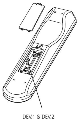
VOLTE A COLOCAR A TAMPA DO COMPARTIMENTO DAS PILHAS, ALINHANDO E INSERINDO AS DUAS PATILHAS NO INTERIOR DOS ORIFÍCIOS. FAÇA PRESSÃO SOBRE A TAMPA DO COMPARTIMENTO DAS PILHAS ATÉ QUE ESTA FIQUE FECHADA E OIÇA UM ESTALIDO
natural_image
Technical line drawing of a mechanical device with no visible text or symbolsSÄTT TILLBAKA BATTERILUCKAN, SE TILL ATT DEN STÄNGS MED ETT KLICK
natural_image
Line drawing of a remote control box with internal components and a lid (no text or symbols)DEV.1 & DEV.2
SPECIFICATIONER
AMPLIFIER SECTION
Frekvens respons 20 to 20,000 Hz ±0.3dB
www.NADelectronics.com
©2003 NAD ELECTRONICS INTERNATIONAL A DIVISION OF LENBROOK INDUSTRIES LIMITED
- Stereo Integrated Amplifier
- DO NOT ATTEMPT SERVICING OF THIS UNIT YOURSELF. REFER SERVICING TO QUALIFIED SERVICE PERSONNEL
- ATTENTION
- CAUTION
- CAUTION POWER LINES
- OUTDOOR ANTENNA GROUNDING
- QUICK START
- NOTES ON INSTALLATION
- REAR PANEL CONNECTIONS (FIGURE 1)
- DISC INPUT
- CD INPUT
- VIDEO INPUT
- AUX INPUT
- TUNER INPUT
- TAPE 2 IN, OUT
- TAPE 1 IN, OUT
- PRE OUT 1
- MAIN IN
- PRE OUT 2
- VOLUME PRE OUT 2
- BRIDGE MODE
- SOFT CLIPPING™
- IR IN, OUT
- 12V TRIGGER OUT
- SPEAKERS A + SPEAKERS B
- BARE WIRES AND PIN CONNECTORS
- SWITCHED AC OUTLET
- IEC AC MAINS (POWER) INPUT
- FRONT PANEL CONTROLS (FIGURE 2)
- POWER ON/OFF
- REMOTE CONTROL (FIGURE 3) ON AND OFF BUTTONS
- POWER / STAND-BY / PROTECTION INDICATOR
- HEADPHONE SOCKET
- SPEAKERS A & B
- INPUT SELECTORS
- INFRA-RED REMOTE CONTROL COMMAND RECEIVER
- SOFT CLIPPING™ INDICATOR
- BASS & TREBLE CONTROLS
- TONE DEFEAT
- BALANCE
- VOLUME
- BRIDGE MODE INDICATOR
- RECORDING
- TO MAKE A RECORDING
- TAPE TO TAPE COPYING
- BI-AMPING
- POWERDRIVE
- REMOTE CONTROL HANDSET (FIGURE 3)
- POWER ON AND OFF BUTTONS
- SPEAKERS A & B
- MUTE
- INPUTS
- MASTER VOLUME
- TUNER CONTROL
- CD PLAYER CONTROL
- CASSETTE DECK CONTROL
- SPECIFICATIONS
- AMPLIFIER SECTION
- MISE EN ROUTE RAPIDE
- ENTREE / SORTIE "MAGNETOPHONE 2" [TAPE 2 IN, OUT]
- ENTREE / SORTIE "MAGNETOPHONE 1" [TAPE 1 IN, OUT]
- "MARCHE / ARRET" [POWER ON/OFF]
- PRISE "CASQUE" [HEADPHONE]
- "COPIER ENTRE CASSETTES" [TAPE TO TAPE]
- CARACTÉRISTIQUES
- KOPFHÖRERBUCHSE (HEADPHONE)
- SNELSTART
- TAPE 2 IN, OUT [CASSETTERECORDER 2 IN, UIT]
- TAPE 1 IN, OUT [CASSETTERECORDER 1 IN, UIT]
- IR IN, OUT [IR IN, UIT]
- AFSTANDSBEDIENING (AFBEELDING 3) ON/OFF [TOETSEN AAN / UIT]
- TECHNISCHE GEGEVENS
- VERSTERKERDEEL
- TAPE 2 IN, OUT (NASTRO 2 IN, OUT)
- TAPE 1 IN, OUT (NASTRO 1 IN, OUT)
- "POWER ON/OFF" (ACCESO/SPENTO)
- SPECIFICATIONER
- ©2003 NAD ELECTRONICS INTERNATIONAL A DIVISION OF LENBROOK INDUSTRIES LIMITED
Brand : NAD
Model : C372
Category : Integrated amplifier