
C315BEE - Audio Amplifier NAD - Free user manual and instructions
Find the device manual for free C315BEE NAD in PDF.
| Brand and model | NAD C315BEE |
| Product type | Integrated stereo audio amplifier |
| Continuous output power (8 Ω) | 40 W per channel (16 dBW) |
| IHF dynamic power (8 Ω) | 90 W per channel (19.5 dBW) |
| IHF dynamic power (4 Ω) | 110 W per channel (20.4 dBW) |
| Total harmonic distortion (THD) | < 0.02% (20 Hz - 20 kHz) |
| Signal-to-noise ratio (A-weighted, ref. 1 W) | 95 dB |
| Input impedance (line) | 50 kΩ + 100 pF |
| Analog inputs | Disc, CD, Video, AUX, Tuner, Tape (In/Out) |
| Outputs | Speakers (4 Ω min), Headphones (6.35mm jack), Tape Out |
| Tone controls | Bass (±8 dB at 100 Hz), Treble (±5 dB at 10 kHz), Tone Defeat |
| Volume control | Motorized, adjustable via remote control |
| Remote control | Infrared, CR2025 batteries, range up to 5 m |
| Protection | Protection circuit with LED indicator (red) |
| Net dimensions (W × H × D) | 435 × 70 × 242 mm |
| Shipping dimensions (W × H × D) | 435 × 80 × 292 mm |
| Net weight | 5.25 kg |
| Power supply | Mains (detachable cable, plug varies by country) |
| Maintenance and cleaning | Unplug before cleaning. Use a soft, dry or slightly damp cloth. Do not use volatile substances. |
| Spare parts and repairability | Use only parts recommended by the manufacturer. Any repair must be entrusted to qualified personnel. |
Frequently Asked Questions - C315BEE NAD
User questions about C315BEE NAD
0 question about this device. Answer the ones you know or ask your own.
Ask a new question about this device
Download the instructions for your Audio Amplifier in PDF format for free! Find your manual C315BEE - NAD and take your electronic device back in hand. On this page are published all the documents necessary for the use of your device. C315BEE by NAD.
USER MANUAL C315BEE NAD
Owner's Manual
SAVE THESE INSTRUCTIONS FOR LATER USE.
FOLLOW ALL WARNINGS AND INSTRUCTIONS MARKED ON THE AUDIO EQUIPMENT.
1 Read instructions - All the safety and operating instructions should be read before the product is operated.
2 Retain instructions - The safety and operating instructions should be retained for future reference.
3 Heed Warnings - All warnings on the product and in the operating instructions should be adhered to.
4 Follow Instructions - All operating and use instructions should be followed.
5 Cleaning - Unplug this product from the wall outlet before cleaning. Do not use liquid cleaners or aerosol cleaners. Use a damp cloth for cleaning.
6 Attachments - Do not use attachments not recommended by the product manufacturer as they may cause hazards.
7 Water and Moisture - Do not use this product near water-for example, near a bath tub, wash bowl, kitchen sink, or laundry tub; in a wet basement; or near a swimming pool; and the like.
8 Accessories - Do not place this product on an unstable cart, stand, tripod, bracket, or table. The product may fall, causing serious injury to a child or adult, and serious damage to the product. Use only with a cart, stand, tripod, bracket, or table recommended by the manufacturer, or sold with the product. Any mounting of the product should follow the manufacturer's instructions, and should use a mounting accessory recommended by the manufacturer.
9 A product and cart combination should be moved with care. Quick stops, excessive force, and uneven surfaces may cause the product and cart combination to overturn.
10 Ventilation - Slots and openings in the cabinet are provided for ventilation and to ensure reliable operation of the product and to protect it from overheating, and these openings must not be blocked or covered. The openings should never be blocked by placing the product on a bed, sofa, rug, or other similar surface. This product should not be placed in a built-in installation such as a bookcase or rack unless proper ventilation is provided or the manufacturer's instructions have been adhered to.
11 Power Sources - This product should be operated only from the type of power source indicated on the marking label. If you are not sure of the type of power supply to your home, consult your product dealer or local power company. The primary method of isolating the amplifier from the mains supply is to disconnect the mains plug. Ensure that the mains plug remains accessible at all times. Unplug the AC power cord from the AC outlet if the unit will not be used for several months or more.
12 Grounding or Polarization - This product may be equipped with a polarized alternating-current line plug (a plug having one blade wider than the other). This plug will fit into the power outlet only one way. This is a safety feature. If you are unable to insert the plug fully into the outlet, try reversing the plug. If the plug should still fail to fit, contact your electrician to replace your obsolete outlet. Do not defeat the safety purpose of the polarized plug.
13 Power - Cord Protection - Power-supply cords should be routed so that they are not likely to be walked on or pinched by items placed upon or against them, paying particular attention to cords at plugs, convenience receptacles, and the point where they exit from the product.
14 Outdoor Antenna Grounding - If an outside antenna or cable system is connected to the product, be sure the antenna or cable system is grounded so as to provide some protection against voltage surges and built-up static charges. Article 810 of the National Electrical Code, ANSI/NFPA 70, provides information with regard to proper grounding of the mast and supporting structure, grounding of the lead-in wire to an antenna discharge unit, size of grounding conductors, location of antenna discharge unit, connection to grounding electrodes, and requirements for the grounding electrode.
NOTE TO CATV SYSTEM INSTALLER
This reminder is provided to call the CATV system installer's attention to Section 820-40 of the NEC which provides guidelines for proper grounding and, in particular, specifies that the cable ground shall be connected to the grounding system of the building, as close to the point of cable entry as practical.
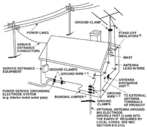
15 Lightning - For added protection for this product during a lightning storm, or when it is left unattended and unused for long periods of time, unplug it from the wall outlet and disconnect the antenna or cable system. This will prevent damage to the product due to lightning and power-line surges.
16 Power Lines - An outside antenna system should not be located in the vicinity of overhead power lines or other electric light or power circuits, or where it can fall into such power lines or circuits. When installing an outside antenna system, extreme care should be taken to keep from touching such power lines or circuits as contact with them might be fatal.
17 Overloading - Do not overload wall outlets, extension cords, or integral convenience receptacles as this can result in a risk of fire or electric shock.
18 Object and Liquid Entry - Never push objects of any kind into this product through openings as they may touch dangerous voltage points or short-out parts that could result in a fire or electric shock. Never spill liquid of any kind on the product.
WARNING: THE APPARATUS SHALL NOT BE EXPOSED TO DRIPPING OR SPLASHING, AND OBJECTS FILLED WITH LIQUIDS, SUCH AS VASES, SHALL NOT BE PLACED ON THE APPARATUS. AS WITH ANY ELECTRONIC PRODUCTS, USE CARE NOT TO SPILL LIQUIDS INTO ANY PART OF THE SYSTEM. LIQUIDS CAN CAUSE A FAILURE AND/OR A FIRE HAZARD.
19 Damage Requiring Service - Unplug this product from the wall outlet and refer servicing to qualified service personnel under the following conditions:
a) When the power-supply cord or plug is damaged.
b) If liquid has been spilled, or objects have fallen into the product.
c) If the product has been exposed to rain or water.
d) If the product does not operate normally by following the operating instructions. Adjust only those controls that are covered by the operating instructions as an improper adjustment of other controls may result in damage and will often require extensive work by a qualified technician to restore the product to its normal operation.
e) If the product has been dropped or damaged in any way.
f) when the product exhibits a distinct change in performance-this indicates a need for service.
20 Replacement Parts - When replacement parts are required, be sure the service technician has used replacement parts specified by the manufacturer or have the same characteristics as the original part. Unauthorized substitutions may result in fire, electric shock, or other hazards.
21 Safety Check - Upon completion of any service or repairs to this product, ask the service technician to perform safety checks to determine that the product is in proper operating condition.
22 Wall or Ceiling Mounting - The product should be mounted to a wall or ceiling only as recommended by the manufacturer.
WARNING

TO PREVENT FIRE OR SHOCK HAZARD, DO NOT EXPOSE THIS APPLIANCE TO RAIN OR MOISTURE. THE LIGHTNING FLASH WITH ARROWHEAD SYMBOL, WITHIN AN EQUILATERAL TRIANGLE, IS INTENDED TO ALERT THE USER TO THE PRESENCE OF UNINSULATED "DANGEROUS VOLTAGE" WITHIN THE PRODUCT'S ENCLOSURE THAT MAY BE OF SUFFICIENT MAGNITUDE TO CONSTITUTE A RISK OF ELECTRIC SHOCK TO PERSONS.

THE EXCLAMATION POINT WITHIN AN EQUILATERAL TRIANGLE IS INTENDED TO ALERT THE USER TO THE PRESENCE OF IMPORTANT OPERATING AND MAINTENANCE (SERVICING) INSTRUCTIONS IN THE LITERATURE ACCOMPANYING THE APPLIANCE

CAUTION
Changes or modifications to this equipment not expressly approved by NAD Electronics for compliance could void the user's authority to operate this equipment.
CAUTION REGARDING PLACEMENT
To maintain proper ventilation, be sure to leave a space around the unit (from the largest outer dimensions including projections) equal to, or greater than, shown below.
Left and Right Panels : 10 cm
Rear Panel : 10 cm
Top Panel : 50 cm
IMPORTANT INFORMATION FOR UK CUSTOMERS

DO NOT cut off the mains plug from this equipment. If the plug fitted is not suitable for the power points in your home or the cable is too short to reach a power point, then obtain an appropriate safety
approved extension lead or consult your dealer. If, nonetheless, the mains plug is cut off, REMOVE THE FUSE and dispose of the PLUG immediately, to avoid possible shock hazard by inadvertent connection to the mains supply. If this product is not provided with a mains plug, or one has to be fitted, then follow the instructions given below:
IMPORTANT
DO NOT make any connection to the larger terminal which is marked with the letter 'E' or by the safety earth symbol or coloured GREEN or GREEN AND YELLOW.
The wires in the mains lead on this product are coloured in accordance with the following code:
BLUE - NEUTRAL
BROWN - LIVE
As these colours may not correspond with the coloured markings identifying the terminals in your plug, proceed as follows:
The BLUE wire must be connected to the terminal marked with the letter 'N' or coloured BLACK.
The BROWN wire must be connected to the terminal marked with the letter 'L' or coloured RED
When replacing the fuse, only a correctly rated and approved type should be used, and be sure to re-fit the fuse cover.
IF IN DOUBT CONSULT A COMPETENT ELECTRICIAN
This product is manufactured to comply with the radio interference requirements of EEC DIRECTIVE 89/68/EEC and 2006/95/EEC.
NOTES ON ENVIRONMENTAL PROTECTION

At the end of its useful life, this product must not be disposed of with regular household waste but must be returned to a collection point for the recycling of electrical and electronic equipment. The symbol on the product, user's manual and packaging, point this out.
The materials can be reused in accordance with their markings. Through re-use, recycling of raw materials, or other forms of recycling of old products, you are making an important contribution to the protection of our environment.
Your local administrative office can advise you of the responsible waste disposal point.
Model No.:
Serial No.:
FRONT PANEL CONTROLS (FIGURE 1)

REAR PANEL CONNECTIONS (FIGURE 2)
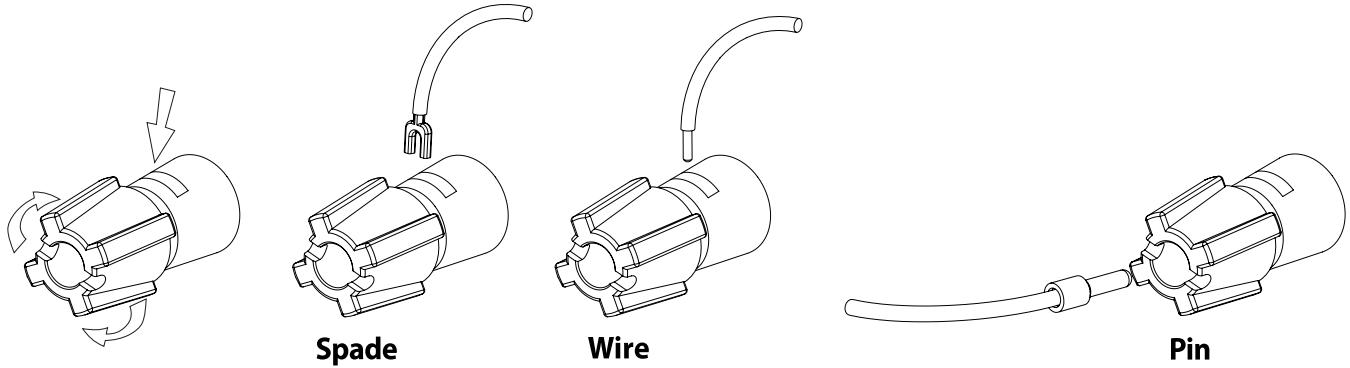
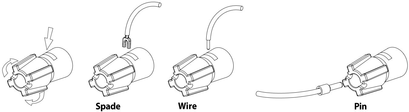
BARE WIRES AND PIN CONNECTORS (FIGURE 3)

WARNING
The Terminals marked with this symbol are hazardous live. External wiring connected to these terminals requires installation by an instructed person or the use of ready-made leads or cords.
NOTES ON INSTALLATION
Your NAD C315BEE should be placed on a firm, level surface. Avoid placing the unit in direct sunlight or near sources of heat and damp. Allow adequate ventilation. Do not place the unit on a soft surface like a carpet. Do not place it in an enclosed position such a bookcase or cabinet that may impede the air-flow through the ventilation slots. Make sure the unit is switched off before making any connections.
The RCA sockets on your NAD C315BEE are colour coded for convenience. Red and white are Right and Left audio respectively.
Use high quality leads and sockets for optimum performance and reliability. Ensure that leads and sockets are not damaged in any way and all sockets are firmly pushed home.
For best performance, use quality speaker leads of 16 gauge (1.5mm) thickness or more. If the unit is not going to be used for some time, disconnect the plug from the AC socket.
Should water get into your NAD C315BEE, shut off the power to the unit and remove the plug from the AC socket. Have the unit inspected by a qualified service technician before attempting to use it again.
DO NOT REMOVE THE COVER, THERE ARE NO USER-SERVICEABLE PARTS INSIDE.
Use a dry soft cloth to clean the unit. If necessary, lightly dampen the cloth with soapy water. Do not use solutions containing benzol or other volatile agents.
QUICK START
1 Connect the speakers to the rear Speaker terminals and sources to the relevant rear input sockets.
2 Plug in the AC power cord.
3 Switch to ON, the POWER button on the rear panel, to turn the C315BEE to standby.
4 Press the front panel Standby button to turn the NAD C315BEE on.
5 Press the required input selector.
FRONT PANEL CONTROLS (FIGURE 1)
- Standby Button: The Standby Button turns on and to standby the C315BEE. This button will only function when the Power/Standby/Protection LED is either amber representing the standby state, or green representing the on-state.
2 Power/Standby/Protection LED: Upon switching the power on, the LED will light up red for a few seconds before the protection circuit is deactivated. The LED will then turn green, representing normal operation. In cases of serious abuse of the amplifier, such as overheating, excessively low loudspeaker impedance, short circuit etc. the amplifier will engage its Protection circuitry, indicated by the LED turning from green to red, and the sound being muted. In such a case, turn the amplifier off by the rear panel POWER switch, wait for it to cool down and/or check the speaker connections, making sure the overall loudspeaker impedance doesn't go below 4 ohms. Once the cause for the protection circuitry to engage has been removed, switch ON the rear POWER button and then the Standby Button to resume normal operation.
3 Headphone socket :A 1/4" stereo jack socket is supplied for headphone listening and will work with conventional headphones of any impedance. Inserting a headphone jack into this socket automatically switches off the loudspeakers. The volume, tone and balance controls are operative for headphone listening. Use a suitable adaptor to connect headphones with other types of sockets, such as 3.5mm stereo 'personal stereo'jack plugs.
SAFETY NOTES
- Make certain that the volume control is turned to minimum (fully anticlockwise) before connecting or disconnecting headphones. Listening at high levels can damage your hearing.
- Excessive sound pressure from earphones or headphones can cause hearing loss.
4 Input selectors: These buttons select the active input to the NAD C315BEE and the signal sent to the loudspeakers and the Tape outputs. The buttons on the remote control handset duplicate these buttons. Green LEDs just above each button will indicate which input is currently selected.
TAPE Selects the output from a tape recorder when playing back tape recordings being made through the Tape sockets.
TUNER Selects the tuner (or other line-level source) connected to the Tuner sockets as the active input.
AUX Selects a line-level source connected to the AUX sockets as the active input.
VIDEO Selects the VCR (or stereo TV/Satellite/Cable receiver) connected to the VIDEO sockets as the active input.
CD Selects the CD (or other line-level source) connected to the CD sockets as the active input.
DISC/MP (Media Player) Selects a line-level source connected to the DISC sockets as the active input. When a 3.5mm stereo plug is inserted into the MP socket, the indicator above the socket will illuminate, and the DISC line-level source will be disconnected. It is recommended to mute the volume or switch to a different input before plugging/unplugging the external Media Player cable
5 Infra-red remote control command receiver: The infrared sensor, located behind this circular window, receives commands from the remote control. There must be a clear line-of-sight path from the remote control to this window; if that path is obstructed, the remote control may not work.
NOTES
Direct sunlight or very bright ambient lighting may affect the operating range and angle for the remote control handset.
The remote control handset with the C315BEE supplied is of a universal NAD type, designed to operate several NAD models.
6 Tone controls: The NAD C315BEE is fitted with BASS and TREBLE tone controls to adjust the tonal balance of your system.
The 12 o'clock position is 'flat' with no boost or cut, and an indent indicates this position. Rotate the control clockwise to increase the amount of Bass or Treble. Rotate the control anti-clockwise to decrease the amount of Bass or Treble. The Tone controls do not affect recordings made using the Tape outputs but will affect the signal going to the Speakers.
7 Tone defeat: The TONE DEFEAT switch by-passes the tone control section of the NAD C315BEE. If the Tone Controls are not normally used and left in the 12 o'clock position, then it is advisable to switch out the Tone Control section altogether by using this switch. In the 'out' position, the Tone Control circuits are active, pushing the TONE DEFEAT switch 'in' bypasses the Tone Control section.
8 Balance: The BALANCE control adjusts the relative levels of the left and right speakers. The 12 o'clock position provides equal level to the left and right channels. A detent indicates this position.
Rotating the control clockwise moves the balance towards the right. Rotating the control anti-clockwise moves the balance to the left. The BALANCE control does not affect recordings made using the Tape outputs but will affect the signal going to the Speakers.
9 Volume: The VOLUME control adjusts the overall loudness of the signals being fed to the loudspeakers. It is motor driven and can be adjusted from the remote control handset. The VOLUME control does not affect recordings made using the Tape outputs but will affect the signal going to the Speakers.
On the remote control handset, press the MUTE button to temporarily switch off the sound to the speakers and headphones. Mute mode is indicated by the active input LED flashing. Press the MUTE button again to restore sound. Mute does not affect recordings made using the Tape outputs but will affect the signal going to the Speakers.
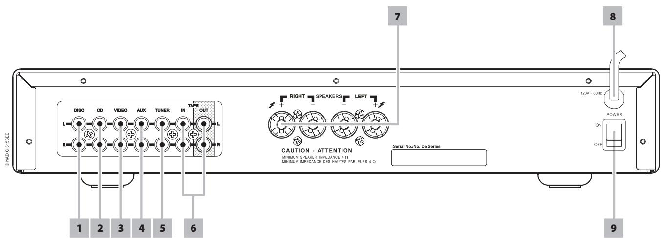
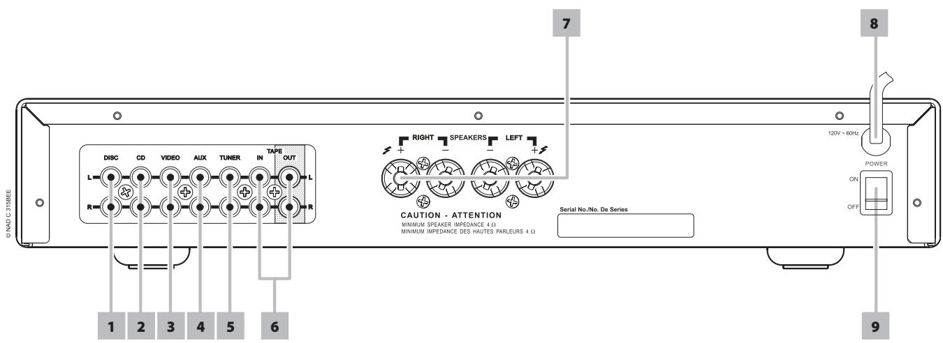
REAR PANEL CONNECTIONS (FIGURE 2)
1 Disc input : Input for additional line level input signals such as CD, Mini Disc player or the output signal from a step-up amplifier for a turntable. Use a twin RCA-to-RCA lead to connect the auxiliary unit's left and right 'Audio Outputs' to this input.
NOTES
When a 3.5mm stereo plug is inserted into the Front Panel MP socket, the indicator above the socket will illuminate, and the DISC line-level source will be disconnected. It is recommended to mute the volume or switch to a different input before plugging/unplugging the external Media Player cable.
2 CD input: Input for a CD or other line-level signal source. Use a twin RCA-to-RCA lead to connect the CD player's left and right 'Audio Outputs' to this input. The NAD C315BEE only accepts analogue signals from your CD player.
3 Video input: Input for the audio signal from a stereo VCR (or stereo TV/Satellite/Cable receiver) or other line-level audio source. Using twin RCA-to-RCA leads, connect to the left and right 'Audio Outputs' of the unit to these inputs. Note: These are audio inputs only.
4 AUX input: Input for additional line level input signals such as another CD player. Use a twin RCA-to-RCA lead to connect the auxiliary unit's left and right 'Audio Outputs' to this input.
5 Tuner input: Input for a tuner or other line-level signal source. Use a twin RCA-to-RCA lead to connect the tuner left and right 'Audio Outputs' to this input.
6 Tape In/Out: Connections for analogue recording and playback to an audio tape recorder of any type. Using twin RCA-to-RCA leads, connect to the left and right 'Audio Output' of the tape machine to the TAPE IN sockets for playback and tape monitoring. Connect the left and right 'Audio Input' of the tape machine to the TAPE OUT sockets for recording.
TO MAKE A RECORDING
When any source is selected, its signal is also fed directly to any tape machine connected to the TAPE OUTPUT for recording.
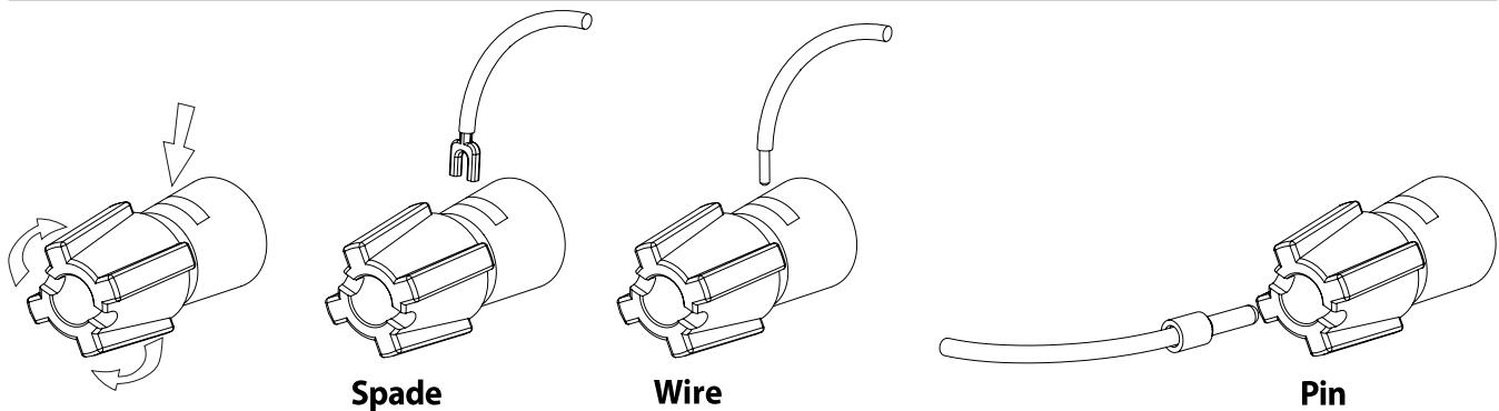
7 Speakers: Speaker terminals for speakers with an impedance of 4 ohms or more. Connect the right speaker to the terminals marked 'R+' and 'R-' ensuring that the 'R+' is connected to the '+' terminal on your loudspeaker and the 'R-' is connected to the loudspeaker's '-' terminal. Connect the terminals marked 'L+' and 'L-' to the left speaker in the same way. Always use heavy duty (16 gauge; 1.5mm, or thicker) stranded wire to connect loudspeakers to your NAD C315BEE. The high-current binding post terminals can be used as a screw terminal for cables terminating in spade or pin sockets or for cables with bare wire ends.
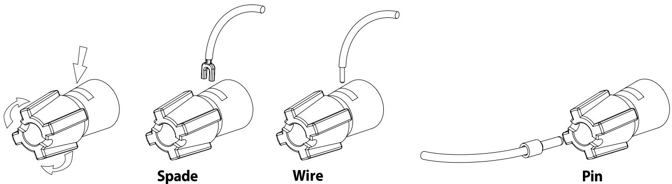
BARE WIRES AND PIN CONNECTORS (FIGURE 3)
Bare wires and pin sockets should be inserted into the hole in the shaft of the terminal. Unscrew the speaker terminal's plastic bushing until the hole in the screw shaft is revealed. Insert the pin or bare cable end into the hole and secure the cable by tightening down the terminal's bushing. Ensure bare wire from the speaker cables does not touch the back panel or another socket. Ensure that there is only 1/2" (1cm) of bare cable or pin and no loose strands of speakers wire.
8 AC line cord : Plug the AC power cord into a live AC wall socket. Make sure all connections have been made before connecting to mains.
9 POWER Switch: The POWER switch supplies the master AC mains power for the C315BEE. When this switch is in the ON position the C315BEE is in standby as shown by the amber Status Condition L.E.D. above the power switch on the front panel. If you intend not to use the amplifier for long periods of time, switch the POWER switch to the OFF position.
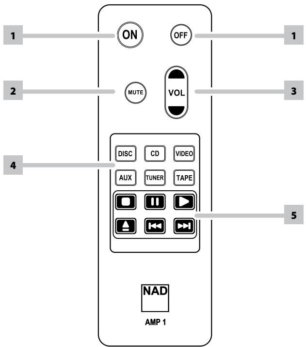
REMOTE CONTROL HANDSET AMP 1 (FIGURE 4)
The Remote Control handset handles all the key functions of the NAD C315BEE and has additional controls to remotely operate NAD CD machines. It will operate up to a distance of 16ft (5m). Alkaline batteries are recommended for maximum operating life. One CR2025 battery should be fitted in the battery compartment at the back of the Remote Control handset (see Figure 4). Please refer to previous sections of the manual for a full description of individual functions. When a command from the remote control is received, the Standby/protection indicator will blink.
1 POWER ON & OFF: The NAD C315BEE remote has a separate On and Off button. This can be particularly useful to keep components within a system "insync": This way all components will switch to stand-by when Off is pressed or switch to operating mode when On is pressed, instead of some components switching On when the amplifier is switched to Stand-by. (Note that the other components have to be capable of responding to the separate On and Off commands as well). Press the ON button to switch the unit from Stand-by to the operating mode; The Stand-by indicator (Fig. 1; No. 2) will turn from amber, to red, then to green. Press the OFF button to switch the unit to the Stand-by mode: The Stand-by indicator will light up amber.
2 MUTE: Press the MUTE Button to temporarily switch off the sound to the speakers and headphones. Press MUTE again to restore sound. Mute does not affect recordings made using the Tape output but will affect the signal going to the Speakers.
3 MASTER VOLUME : Press the MASTER VOLUME ▲ or ▼ buttons to respectively increase or decrease the loudness level. Release the button when the desired level is reached. The motorised Volume Control on the front panel will indicate the level set. The Master Volume buttons do not affect recordings made using the Tape outputs but will affect the signal going to the Speakers.
4 INPUTS: The input selector buttons perform the same functions as the buttons labelled the same on the front panel.
5 CD PLAYER CONTROL :
(for use with NAD CD-Player)
II engages Pause
■ engages Stop
▶ engages Play.
engages reverse Skip
▶▶I engages forward Skip.
▲ engages CD drawer Open/Close; Press once to open the CD drawer then once again to close the CD drawer and start playback.
NOTES
The remote control handset supplied with the C315BEE is of a universal NAD type, designed to operate several NAD models.
Direct sunlight or very bright ambient lighting may affect the operating range and angle for the remote control handset.
REMOTE CONTROL HANDSET AMP 1 (FIGURE 4)
flowchart
graph TD
    A["ON"] --> B["MUTE"]
    C["OFF"] --> D["VOL"]
    E["DISC"] --> F["CD"]
    G["VIDEO"] --> H["AUX"]
    I["TUNER"] --> J["TAPE"]
    K["NOT"] --> L["NOT"]
    M["NAD AMP 1"] --> N["AMP 1"]
    style A fill:#f9f,stroke:#333
    style C fill:#f9f,stroke:#333
    style E fill:#f9f,stroke:#333
    style F fill:#ccf,stroke:#333
    style G fill:#ccf,stroke:#333
    style H fill:#ccf,stroke:#333
    style I fill:#ccf,stroke:#333
    style J fill:#ccf,stroke:#333
    style K fill:#ccf,stroke:#333
    style L fill:#ccf,stroke:#333
    style M fill:#ccf,stroke:#333
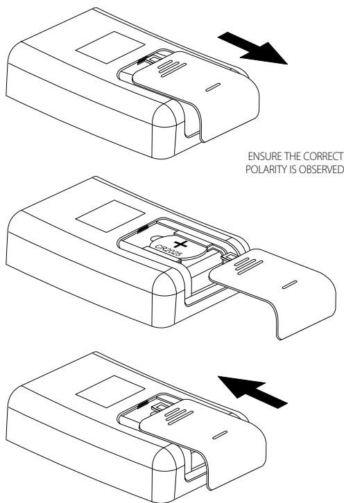
WARNING
Do not expose the battery or remote to excessive heat, fire or alike.
| PROBLEM | CAUSE | SOLUTION |
| NO SOUND | Power AC lead unplugged or power not switched on | Check if AC lead is plugged in and power switched on |
| Mute on | Switch off Mute | |
| Headphones inserted | Unplug the headphones | |
| NO SOUND ONE CHANNEL | Balance control not centered | Center Balance control |
| Speaker not properly connected or damaged | Check connections and speakers | |
| Input lead disconnected or damaged | Check leads and connections | |
| WEAK BASS / DIFFUSED STEREO IMAGE | Speakers wired out of phase | Check connections to all speakers in the system |
| REMOTE CONTROL HANDSET NOT WORKING | Battery flat, or incorrectly inserted | Check or replace battery |
| IR transmitter or receiver windows obstructed | Remove obstruction | |
| IR receiver in direct sun or very bright ambient light | Place unit away from direct sun, reduce amount of ambient light | |
| POWER/PROTECTION LED TURNS RED DURING OPERATION | Amplifier has overheated | Turn amplifier off, make sure ventilation slots on top and bottom of amplifier are not blocked. After amplifier has cooled down, turn back on. |
LINE LEVEL INPUTS (DISC, CD, VIDEO, AUX, TUNER, TAPE) MEASURED AT SPEAKERS OUTPUT
| Input impedance (R and C) | 50kΩ + 100pF |
| Input sensitivity (ref. rated power) | 200mV |
| Maximum input signal | 7V |
LINE LEVEL OUTPUTS
| Output impedance | Tape | Source Z + 600Ω |
TONE CONTROLS
| Treble | ±5dB at 10kHz | |
| Bass | ±8dB at 100Hz | |
| Continuous output power into 8^2 | 40W (16dBW) | |
| Rated distortion (THD 20Hz - 20kHz) | 0.02% | |
| Clipping power (maximum continuous power per channel 4Ω and 8Ω) | 40W | |
| IHF Dynamic headroom | 8Ω | 45W, +16.5dB |
| 4Ω | 60W, +17.8dB | |
| IHF dynamic power (maximum short term power per channel) | 8Ω | 90W (19.5dBW) |
| 4Ω | 120W (20.8dBW) | |
| Damping factor (ref. 8Ω, 1kHz) | >200 | |
| Voltage gain | 39dB | |
| Signal/noise ratio, A-weighted ^1 | ref. 1W | 95dB |
| THD + Noise ^3 | <0.02% | |
| SMPTE IM ^4 | <0.02% | |
| IHF IM ^5 | <0.01% | |
| Headphone output impedance | 68Ω |
PHYSICAL SPECIFICATIONS
| Dimensions (W x H x D)6 | Net | 435 x 70 x 242mm |
| Gross | 435 x 80 x 292mm | |
| Net weight | 5.25kg (11.5lb) | |
| Shipping weight | 6.5kg (14.3lb) |
1 From CD input to speakers output, volume setting for 500mV in, 8Ω 1W out
2 Minimum power per channel, 20Hz - 20kHz, both channels driven with no more than rated distortion.
3 Total harmonic distortion, 20Hz - 20kHz from 250mW to rated output
4 Intermodulation distortion, 60Hz - 7kHz, 4:1, from 250mW to rated output
5 CCIF IM distortion, 19 + 20kHz rated output
6 Gross dimensions include feet, volume knob and extended speaker terminals.
Specifications are subject to change without notice. For updated documentation and features please log onto www.nadelectronics.com for the latest information about your C315BEE.
CONSERVEZ CES INSTRUCTIONS AFIN DE POUVOIR VOUS EN SERVIR ULTÉRIEUREMENT. TENEZ COMPTE DE TOUS LES AVERTISSEMENTS ET SUIVEZ TOUTES LES INSTRUCTIONS QUE VOUS TROUVEREZ SUR LE MATÉRIEL AUDIO.
BRANCHEMENTS SUR LE PANNEAU ARRIERE (FIGURE 2)

FILS NUS ET BORNES A BROCHES (FIGURE 3)


ATTENTION DANGER
WAARSCHUWING M.B.T. PLAATSING
BEDIENINGSELEMENTEN ACHTERPANEEL (FIG. 2)

ONGEÏSOLEERDE DRAĐEN EN PIN-CONNECTORS (FIG. 3)

WAARSCHUWING
CONEXIONES DEL PANEL TRASERO (FIGURA 2)
CONECTORES DE CABLE DESNUDO Y DE PATILLAS (FIGURA 3)

AVISO
CONNESSIONI DEL PANNELLO POSTERIORE (FIGURA 2)

FILI SCOPERTI E CONNETTORI A PIEDINI (FIGURA 3)

ATTENZIONE
ATTENZIONE
ENTRATE DI LIVELLO DI LINEA (DISC, CD, VIDEO, AUX, TUNER, TAPE) MISURATE ALL'USCITA DEI DIFFUSORI
Gäller enbart USA/Kanada: This reminder is provided to call the CATV system installer's attention to Section 820-40 of the NEC which provides guidelines for proper grounding and, in particular, specifies that the cable ground shall be connected to the grounding system of the building, as close to the point of cable entry as practical.

KONTROLLER PÅ APPARATENS BAKSIDA (FIGUR 2)

SKALADE KABLAR OCH PINN-KONTAKTER (FIGUR 3)


WARNING
SKALADE KABLAR OCH PINN-KONTAKTER (FIGUR 3)
www.NADelectronics.com
©2007 NAD ELECTRONICS INTERNATIONAL
A DIVISION OF LENBROOK INDUSTRIES LIMITED
- SAVE THESE INSTRUCTIONS FOR LATER USE.
- FOLLOW ALL WARNINGS AND INSTRUCTIONS MARKED ON THE AUDIO EQUIPMENT.
- NOTE TO CATV SYSTEM INSTALLER
- WARNING: THE APPARATUS SHALL NOT BE EXPOSED TO DRIPPING OR SPLASHING, AND OBJECTS FILLED WITH LIQUIDS, SUCH AS VASES, SHALL NOT BE PLACED ON THE APPARATUS. AS WITH ANY ELECTRONIC PRODUCTS, USE CARE NOT TO SPILL LIQUIDS INTO ANY PART OF THE SYSTEM. LIQUIDS CAN CAUSE A FAILURE AND/OR A FIRE HAZARD.
- WARNING
- CAUTION
- CAUTION REGARDING PLACEMENT
- IMPORTANT INFORMATION FOR UK CUSTOMERS
- IMPORTANT
- IF IN DOUBT CONSULT A COMPETENT ELECTRICIAN
- NOTES ON ENVIRONMENTAL PROTECTION
- NOTES ON INSTALLATION
- DO NOT REMOVE THE COVER, THERE ARE NO USER-SERVICEABLE PARTS INSIDE.
- QUICK START
- FRONT PANEL CONTROLS (FIGURE 1)
- SAFETY NOTES
- NOTES
- REAR PANEL CONNECTIONS (FIGURE 2)
- TO MAKE A RECORDING
- BARE WIRES AND PIN CONNECTORS (FIGURE 3)
- REMOTE CONTROL HANDSET AMP 1 (FIGURE 4)
- CD PLAYER CONTROL :
- CONSERVEZ CES INSTRUCTIONS AFIN DE POUVOIR VOUS EN SERVIR ULTÉRIEUREMENT. TENEZ COMPTE DE TOUS LES AVERTISSEMENTS ET SUIVEZ TOUTES LES INSTRUCTIONS QUE VOUS TROUVEREZ SUR LE MATÉRIEL AUDIO.
- ATTENTION DANGER
- WAARSCHUWING M.B.T. PLAATSING
- WAARSCHUWING
- AVISO
- ATTENZIONE
- SKALADE KABLAR OCH PINN-KONTAKTER (FIGUR 3)
Brand : NAD
Model : C315BEE
Category : Audio Amplifier