
925 - Audio Amplifier NAD - Free user manual and instructions
Find the device manual for free 925 NAD in PDF.
| Product Type | THX Multi-Channel Power Amplifier |
| Number of Channels | 5 Channels |
| Output Power (8 ohms) | 200 W per channel (RMS) |
| Output Power (4 ohms) | 400 W per channel (RMS) |
| Frequency Response | 20 Hz - 20 kHz ±0.1 dB |
| Total Harmonic Distortion | <0.05% |
| Signal-to-Noise Ratio | >100 dB (A-weighted) |
| Input Impedance | 50 kΩ |
| Gain | 29 dB |
| Power Supply | 115 V AC or 230 V AC (depending on model) |
| Power Consumption | 1200 W (max) |
| Dimensions (W x H x D) | 435 x 195 x 385 mm |
| Weight | 22.7 kg |
| Technologies | Soft Clipping, Class A dual-differential input circuit, Holmgren™ toroidal transformer |
| Protections | Over-temperature, DC offset, short-circuit, fuses |
| Connections | 5 RCA inputs, 5 speaker outputs (binding posts compatible with banana plugs) |
| Certification | THX Ultra |
| Maintenance | Clean with a soft, dry cloth. Do not use solvents. |
| Safety | Do not expose to moisture. Unplug if liquid is spilled. Provide at least 75 mm ventilation above. |
| Replacement Parts | Contact NAD customer service for replacement parts. |
Frequently Asked Questions - 925 NAD
User questions about 925 NAD
0 question about this device. Answer the ones you know or ask your own.
Ask a new question about this device
Download the instructions for your Audio Amplifier in PDF format for free! Find your manual 925 - NAD and take your electronic device back in hand. On this page are published all the documents necessary for the use of your device. 925 by NAD.
USER MANUAL 925 NAD
THE FOLLOWING PRECAUTIONS AND SAFETY INSTRUCTIONS ARE REQUIREMENTS OF UL AND CSA SAFETY REGULATIONS

ATTENTION:
RISQUE DE CHOC ELECTRIQUE NE PAS OUVIR
CAUTION
RISK OF ELECTRIC SHOCK DO NOT OPEN

CAUTION: TO REDUCE THE RISK OF ELECTRIC SHOCK, DO NOT REMOVE COVER OR BACK) ATTENTION: AFIN DEVITER UN CHOC ELECTRIQUE ET LES CONEQUENCES GRAVES OUI POURRAIENT EN RESULTTER, TENTEZ PAS D'OUVRIR L'APPAREL ET DE TOUCHER AUX COMPOSANTS INTERNES SANS LA PRESENCE D'une SERVICE PERSONNEL
WARNING: TO REDUCE THE RISK OF FIRE OR ELECTRIC SHOCK, DO NOT EXPOSE THIS UNIT TO RAIN OR MOISTURE.

graphic symbol of a lightning flash with arrow point within a triangle signifies at there is dangerous voltage within the unit and it poses a hazard to anyone removing the cover to gain access to the interior of the unit. Only qualified personnel should make any such attempt.

A graphic symbol of an exclamation point within an equilateral triangle warns the user of the device that it is necessary to refer to the instruction manual and its warnings for proper operation of the unit.

Do not place this unit on an unstable cart, stand or tripod, bracket or table. The unit may fall, causing serious injury to a child or adult and serious damage to the unit. Use only with a cart, stand, tripod, bracket or table recommended by the manufacturer or sold with the unit. Any mounting of the device on a wall or ceiling should follow the manufacturer's instructions e a mounting accessory recommended by the manufacturer.
An appliance and cart combination should be moved with care. Quick stops, excessive force and uneven surfaces may cause the appliance and cart combination to overturn.
Read and follow all the safety and operating instructions before connecting or using this unit. Retain this notice and the owner's manual for future reference.
All warnings on the unit and its operating instructions should be adhered to.
Do not use this unit near water: for example, near a bath tub, washbowl, kitchen sink, laundry tub, in a wet basement or near a swimming pool.
The unit should be installed so that its location or position does not interfere with its proper ventilation. For example, it should not be situated on a bed, sofa, rug or similar surface that may block the ventilation openings; or placed in a built-in installation, such as a bookcase or cabinet, that may impede the flow of air through its ventilation openings.
The unit should be situated away from heat sources such as radiators, heat registers, stoves or other devices (including amplifiers) that produce heat
The unit should be connected to a power supply outlet only of the voltage and frequency marked on its rear panel.
The power supply cord should be routed so that it is not likely to be walked on or pinched, especially near the plug, convenience receptacles, or where the cord exits from the unit
Unplug the unit from the wall outlet before cleaning. Never use benzine, thinner or other solvents for cleaning. Use only a soft damp cloth.
The power supply cord of the unit should be unplugged from the wall outlet when it is to be unused for a long period of time.
Care should be taken so that objects do not fall, and liquids are not spilled, into the enclosure through any openings.
This unit should be serviced by qualified service personnel when:
(1) The power cord or the plug has been damaged; or
(2) Objects have fallen, or liquid has been spilled into the unit; or
(3) The unit has been exposed to rain or liquids of any kind; or
(4) The Unit does not appear to operate normally or exhibits a marked change in performance; or
(5) The device has been dropped or the enclosure damaged.
DO NOT ATTEMPT SERVICING OF THIS UNIT YOURSELF. REFER SERVICING TO QUALIFIED SERVICE PERSONNEL.
Upon completion of any servicing or repairs, request the service shop's assurance that only Factory Authorized Replacement Parts with the same characteristics as the original parts have been used, and that the routine safety checks have been performed to guarantee that the equipment is in safe operating condition.
REPLACEMENT WITH UNAUTHORIZED PARTS MAY RESULT IN FIRE. ELECTRIC SHOCK OR OTHER HAZARDS.
CAUTION: TO PREVENT ELECTRIC SHOCK, MATCH WIDE BLADE OF PLUG TO WIDE SLOT, FULLY INSERT.
ATTENTION: POUR EVITER LES CHOCS ÉLECTRIQUES, INTRODUIRE LA LAME LA PLUS LARGE DE LA FICHE DANS LA BORNE CORRESPONDANTE DE LA PRESE ET POUSSER JUSQU'AU FOND.
If an indoor antenna is used (either built into the set or installed separately), never allow any part of the antenna to touch the metal parts or other electrical appliances such as a lamp, TV set etc.
CAUTION - POWER LINES: ANY OUTDOOR ANTENNA MUST BE LOCATED AWAY FROM ALL POWER LINES.
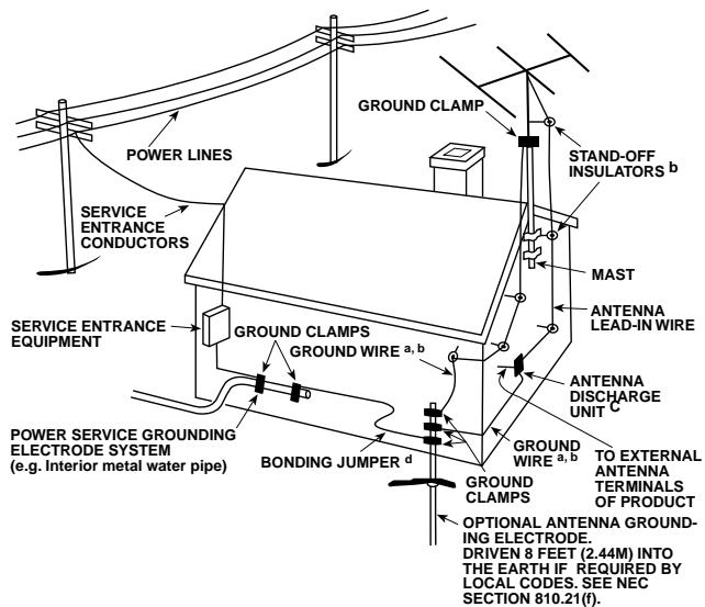
OUTDOOR ANTENNA GROUNDING
If an outside antenna is connected to your tuner or tuner-preamplifier, be sure the antenna system is grounded so as to provide some protection against voltage surges and built-up, static charges. Section 810 or the National Electrical Code ANSI/NFPA NO. 70-1984, provides information with respect to proper grounding of the mast and supporting structure, grounding of the lead-in wire to an antenna discharge unit, size of grounding conductors, location of antenna discharge unit, connection to grounding electrodes and requirements for the grounding electrode.
(1) Use No.10 AWG (5.3mm^2) copper, No. 8 AWG (8.4mm^2) aluminium. No. 17 AWG (1.0mm^2) copper-clad-steel or bronze wire, or larger, as a ground wire.
(2) Secure antenna lead-in and ground wires to house with stand-off insulators spaced from 4-6 feet (1.22 - 1.83m) apart.
(3) Mount antenna discharge unit as close as possible to where lead-in enters house.
(4) Use jumper wire not smaller than No.6 AWG (13.3mm^2) copper, or the equivalent when a separate antenna-grounding electrode is used. See NEC Section 810-21 (j).
EXAMPLE OF ANTENNA GROUNDING AS PER NATIONAL ELECTRICAL CODE INSTRUCTIONS CONTAINED IN ARTICLE 810 - RADIO AND TELEVISION EQUIPMENT.
NOTE TO CATV SYSTEM INSTALLER: This reminder is provided to call the CATV installer's attention to Article 820-22 of the National Electrical Code that provides guidelines for proper grounding and, in particular, specifies that the ground cable ground shall be connected to the grounding system of the building, as close as possible to the point of cable entry as practical.
GB Owner's Manual 5-7
F Manuel d'Installation 8-10
D Bedienungsanleitung 11-13
E Manual del Nombre 14 - 16
I Manuale delle Istruzioni 17 - 19
S Bruksanvisning 20-22
P Manual do Propietario 23-25
Rear Panel Connections
Front Panel Controls
About the 925THX
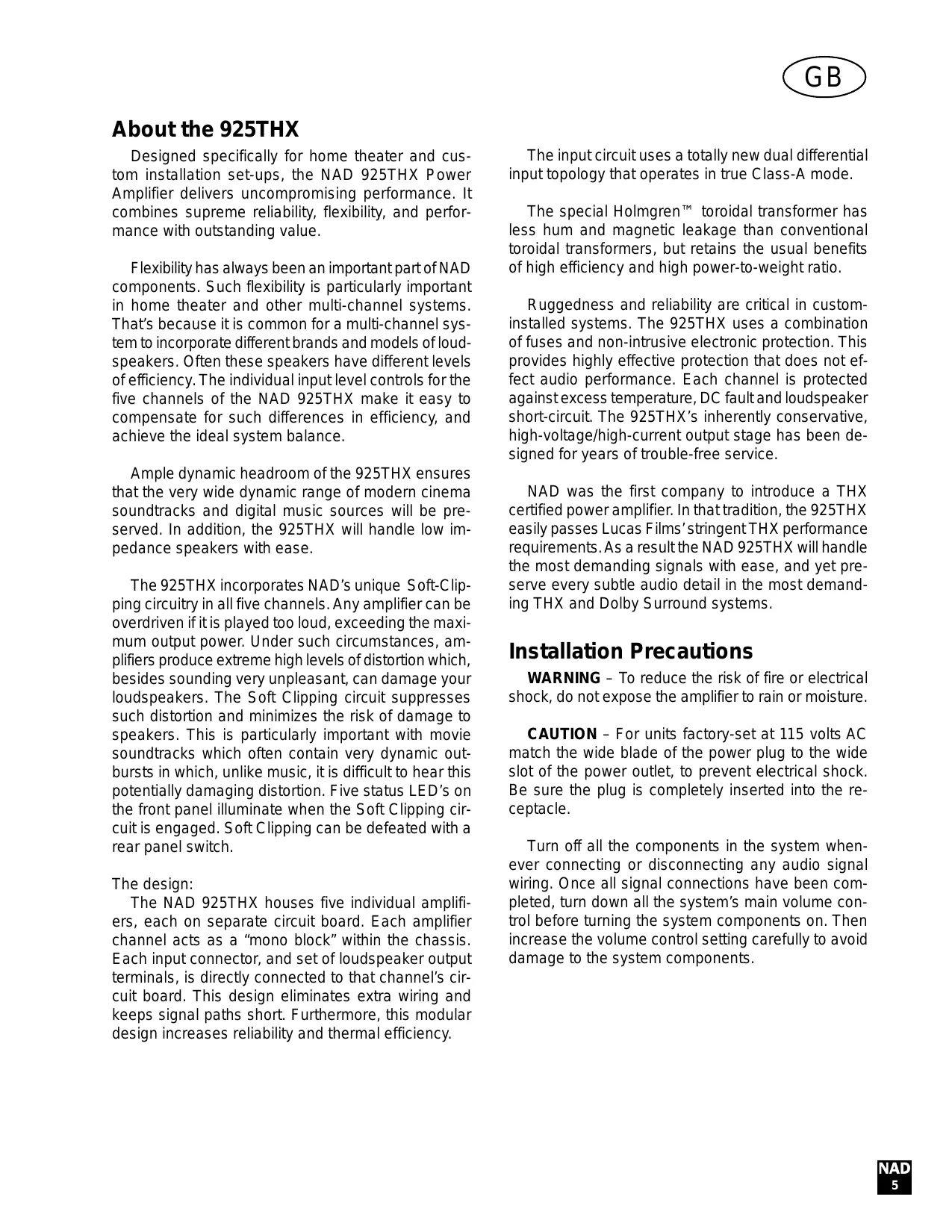
Designed specifically for home theater and custom installation set-ups, the NAD 925THX Power Amplifier delivers uncompromising performance. It combines supreme reliability, flexibility, and performance with outstanding value.
Flexibility has always been an important part of NAD components. Such flexibility is particularly important in home theater and other multi-channel systems. That's because it is common for a multi-channel system to incorporate different brands and models of loudspeakers. Often these speakers have different levels of efficiency. The individual input level controls for the five channels of the NAD 925THX make it easy to compensate for such differences in efficiency, and achieve the ideal system balance.
Ample dynamic headroom of the 925THX ensures that the very wide dynamic range of modern cinema soundtracks and digital music sources will be preserved. In addition, the 925THX will handle low impedance speakers with ease.
The 925THX incorporates NAD's unique Soft-Clipping circuitry in all five channels. Any amplifier can be overdriven if it is played too loud, exceeding the maximum output power. Under such circumstances, amplifiers produce extreme high levels of distortion which, besides sounding very unpleasant, can damage your loudspeakers. The Soft Clipping circuit suppresses such distortion and minimizes the risk of damage to speakers. This is particularly important with movie soundtracks which often contain very dynamic outbursts in which, unlike music, it is difficult to hear this potentially damaging distortion. Five status LED's on the front panel illuminate when the Soft Clipping circuit is engaged. Soft Clipping can be defeated with a rear panel switch.
The design:
The NAD 925THX houses five individual amplifiers, each on separate circuit board. Each amplifier channel acts as a "mono block" within the chassis. Each input connector, and set of loudspeaker output terminals, is directly connected to that channel's circuit board. This design eliminates extra wiring and keeps signal paths short. Furthermore, this modular design increases reliability and thermal efficiency.
The input circuit uses a totally new dual differential input topology that operates in true Class-A mode.
The special Holmgren™ toroidal transformer has less hum and magnetic leakage than conventional toroidal transformers, but retains the usual benefits of high efficiency and high power-to-weight ratio.
Ruggedness and reliability are critical in custom-installed systems. The 925THX uses a combination of fuses and non-intrusive electronic protection. This provides highly effective protection that does not effect audio performance. Each channel is protected against excess temperature, DC fault and loudspeaker short-circuit. The 925THX's inherently conservative, high-voltage/high-current output stage has been designed for years of trouble-free service.
NAD was the first company to introduce a THX certified power amplifier. In that tradition, the 925THX easily passes Lucas Films' stringent THX performance requirements. As a result the NAD 925THX will handle the most demanding signals with ease, and yet preserve every subtle audio detail in the most demanding THX and Dolby Surround systems.
Installation Precautions
WARNING - To reduce the risk of fire or electrical shock, do not expose the amplifier to rain or moisture.
CAUTION - For units factory-set at 115 volts AC match the wide blade of the power plug to the wide slot of the power outlet, to prevent electrical shock. Be sure the plug is completely inserted into the receptacle.
Turn off all the components in the system whenever connecting or disconnecting any audio signal wiring. Once all signal connections have been completed, turn down all the system's main volume control before turning the system components on. Then increase the volume control setting carefully to avoid damage to the system components.
Notes on Installation Location
Read and follow all the safety instructions on the first page of this manual.
To prevent a fire or shock hazard, do not place the amplifier where it will be exposed to any water or moisture. If liquid is accidentally gets into the amplifier, immediately unplug the AC power cord. Do not operate the amplifier again until it has been examined by a service technician.
The amplifier generates a moderate amount of heat, requiring ventilation. Do not obstruct the air outlet grilles on the top or bottom covers. There should be at least 3 inches (7.5 cm) of clearance above the amplifier and 1 inch (2.5 cm) to the sides. Do not place the amplifier in an enclosed area, such as in a bookcase or in a cabinet, unless it is very well ventilated. Be sure there is adequate room behind the amplifier for signal input and speaker output connections. If you want to locate the amplifier on a carpeted floor, place a board under it in order to prevent it from sinking into the carpet, blocking the air inlets on the bottom.
Do not place the amplifier where it will be exposed to direct sun light for prolonged periods of time.
This unit may be installed on any sturdy, level surface. NOTE: The amplifier's weight must always rest on its bottom feet. Never put the amp down on its rear panel, with its front panel facing up. Doing so risks damage to the input/output connectors.
The power transformer in the 925 generates a magnetic hum field of moderate strength. Turntables (especially those with a moving-coil pickup cartridge) should not be located near the amplifier. Magnetic media, such as audio or video tapes and computer diskettes, should not be stored near the amplifier.
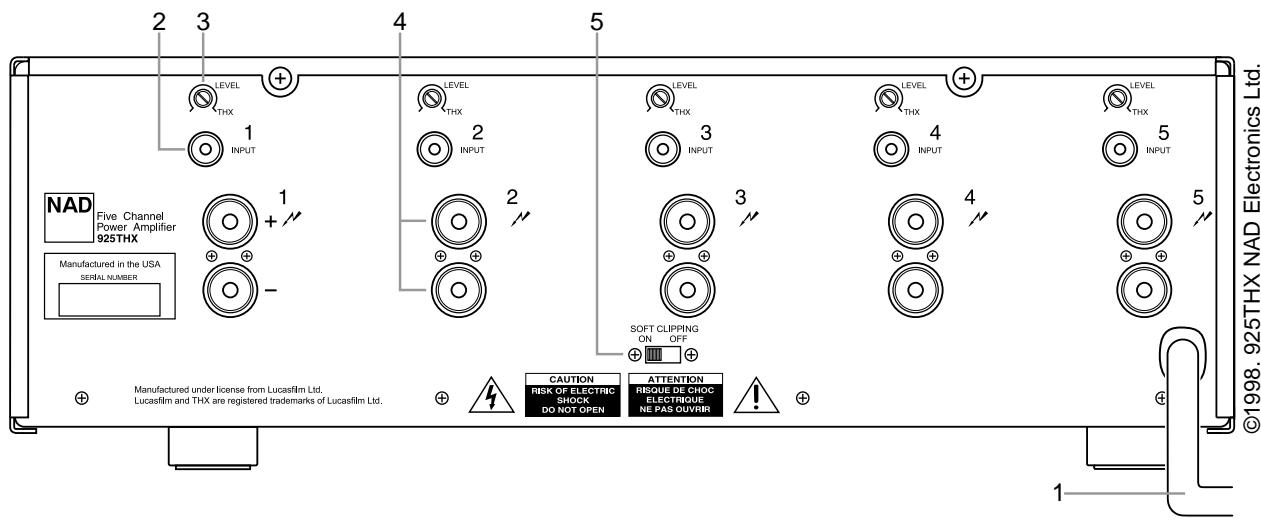
Rear Panel Connections/Controls
1. AC Line Cord
Plug the AC line cord into a nearby wall outlet that provides the correct AC power line voltage, as indicated on the back panel of the unit. Do not plug the amplifier into a convenience outlet on your preamp. The amplifier requires more power than these outlets typically can provide.
2. Inputs
Each of the five independent power amplifiers within the 925THX has its own signal input connector. Before making any connections to the amplifier, make sure the POWER is switched OFF.
Connect the signal cables from the preamplifier, surround sound decoder or other signal source to these inputs.
3. Input Level Controls
The amplifier is equipped with separate input level controls for each channel. Before turning on the 925THX for the first time, make sure all level controls are in their normal full-clockwise position.
Under some circumstances, other settings may be useful for:
(1). Level-matching – In systems that incorporate speakers of varying efficiencies, it may be necessary to reduce the settings of some controls to achieve proper channel-to-channel balance.
(2). Extended volume-control range – Many stereo systems have so much voltage gain that the speakers (or your ears) are over-driven at any volume-control setting higher than 11 or 12 o'clock position of the volume control. As a result you can use only the lower half of the volume control's range, where adjustments are imprecise and channel-balance errors tend to be greater. If all input level controls are reduced, you can turn up your preamplifier's volume control, making effective use of most of its range. (Suggestion: adjust the input level controls so that your preferred maximum sound levels occur at about 2 or 3 o'clock on the volume control.)
As an added benefit, this procedure suppresses any noise produced by the preamp's high-level circuitry (e.g. any residual hum or hiss that does not go away when the Volume is turned down).
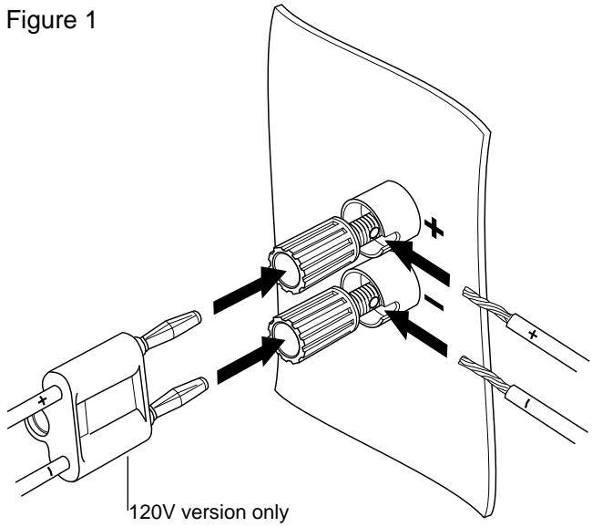
4. Speaker Connections
This amplifier is equipped with special high-current binding-post speaker terminals. Connect the loud-speakers with heavy-duty (16-gauge or thicker) braided wire. Connections may be made in either of two ways. [See Figure 1.*]
(1) Strip off a half-inch (1 cm) of insulation from each speaker wire. In each conductor, twist the thin strands of wire together. Unscrew the knob, insert the bare wire into the opening at the base of the binding post, and tighten the knob until it grasps the wire securely. Check to be sure that there are no loose strands of wire touching the chassis or an adjacent terminal.
(2) Install banana plugs on your speaker wires, and plug them into the end of each binding post. The terminals are separated by 3/4 inch (l9mm), so they will accept dual-banana plugs.*
NOTE - Speakers must operate in phase with each other in order to produce a proper stereo image and to reinforce rather than cancel each other's output at low frequencies. When connecting speakers, take care that the red (positive) terminal on each loudspeaker is connected to the corresponding red (positive) terminal on the amplifier.
5. SOFT CLIPPING
When an amplifier is driven beyond its specified power output it normally produces "hard clipping" or distortion of the signal. Such hard clipping, in addition to sounding unpleasant, can damage the speakers in the system. The NAD Soft Clipping circuit gently limits the output waveform, minimizing audible distortion and reducing the change of speaker damage when the amplifier is overdriven.
We recommend that the Soft Clipping switch on the back panel of the 925THX be left in the ON position when system is being operated at levels that might exceed the amplifier's power capacity.
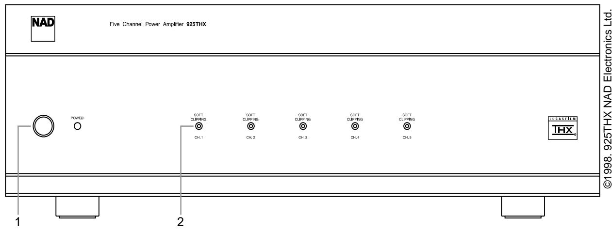
Front Panel Controls
1. Power Switch
Press this button to switch the amplifier on or off. A green LED next to the power button illuminates when the power is on.
2. Soft Clipping Lights
When the Soft Clipping circuit of the 925THX is activated the indicator LED's on the front panel will light.
A propos du 925 THX
Connexions / commands
sur la face arrière
Notas Sobre Lugar de Instalacióntions are those in effect at time of printing.
INSIDE BACK COVER BLANK
Conectores/Controles
del Panel Trasero
1. Cordon de Linea de CA
2. Luci "Soft Clipping"
| Continuous Average Power Output | |
| 20 Hz - 20 kHz; all channels driven, into 8Ω | 125 watts per channel |
| 20 Hz - 20 kHz; two channels driven, into 8Ω | 200 watts per channel |
| IHF Dynamic Power (max short term power/channel) | |
| 8Ω | 160 watts |
| 4Ω | 240 watts |
| 2Ω | 300 watts |
| Input Impedance | 50K ohms |
| Input Sensitivity (for rated power into 8Ω) | 1V |
| Voltage Gain | 29.0 dB |
| Frequency Response | |
| 20 Hz - 20kHz | +0, -0.2 dB |
| 1Hz - 100kHz | +0, -0.2 dB |
| Signal/Noise ratio, A weighted | 95dB ref. 1W |
| THD | |
| 8Ω, 20Hz - 20kHz | < 0.03% |
| 4Ω, 20Hz - 20kHz | < 0.03% |
| IM Distortion | |
| SMPTE | < 0.03% |
| CCIF | < 0.01% |
| Damping Factor, 20Hz - 20kHz | >300 typical |
| Physical Specifications | |
| Dimensions (W x H x D) | 435 x 138 x 415 mm / 17 1/8" x 5 7/16" x 16 3/8" |
| Net weight | 19.0 kg /41.9 lbs |
Specifications or design subject to change without notice.
All specifications are those in effect at time of printing.
(NEW ACOUSTIC DIMENSION)
- THE FOLLOWING PRECAUTIONS AND SAFETY INSTRUCTIONS ARE REQUIREMENTS OF UL AND CSA SAFETY REGULATIONS
- ATTENTION:
- RISQUE DE CHOC ELECTRIQUE NE PAS OUVIR
- CAUTION
- RISK OF ELECTRIC SHOCK DO NOT OPEN
- WARNING: TO REDUCE THE RISK OF FIRE OR ELECTRIC SHOCK, DO NOT EXPOSE THIS UNIT TO RAIN OR MOISTURE.
- DO NOT ATTEMPT SERVICING OF THIS UNIT YOURSELF. REFER SERVICING TO QUALIFIED SERVICE PERSONNEL.
- REPLACEMENT WITH UNAUTHORIZED PARTS MAY RESULT IN FIRE. ELECTRIC SHOCK OR OTHER HAZARDS.
- CAUTION - POWER LINES: ANY OUTDOOR ANTENNA MUST BE LOCATED AWAY FROM ALL POWER LINES.
- OUTDOOR ANTENNA GROUNDING
- EXAMPLE OF ANTENNA GROUNDING AS PER NATIONAL ELECTRICAL CODE INSTRUCTIONS CONTAINED IN ARTICLE 810 - RADIO AND TELEVISION EQUIPMENT.
- About the 925THX
- The design:
- Installation Precautions
- Notes on Installation Location
- Rear Panel Connections/Controls
- AC Line Cord
- Inputs
- Input Level Controls
- Speaker Connections
- SOFT CLIPPING
- Front Panel Controls
- Power Switch
- Soft Clipping Lights
- A propos du 925 THX
- Connexions / commands
- sur la face arrière
- Notas Sobre Lugar de Instalacióntions are those in effect at time of printing. INSIDE BACK COVER BLANK
- Conectores/Controles
- del Panel Trasero
- Cordon de Linea de CA
- Luci "Soft Clipping"
Brand : NAD
Model : 925
Category : Audio Amplifier