LF1000 - Table saw MAKITA - Free user manual and instructions
Find the device manual for free LF1000 MAKITA in PDF.

| Product type | Combined table saw and miter saw (table mode and miter mode) |
| Brand | Makita |
| Model | LF1000 |
| Blade diameter | 260 mm |
| Blade bore | 30 mm (EU) |
| No-load speed | 2,700 min⁻¹ |
| Dimensions (L x W x H) - miter mode | 660 x 650 x 1,220 mm |
| Dimensions (L x W x H) - table mode | 660 x 650 x 1,060 mm |
| Net weight | 32 kg |
| Table dimensions (W x L) | 500 x 555 mm |
| Max. cutting capacities - miter mode (0°/0°) | 68 x 155 mm (H x W) |
| Max. cutting capacities - miter mode (0°/45° left) | 50 x 150 mm (H x W) |
| Max. cutting capacities - table mode (90°) | 70 mm (height) |
| Power supply | Single-phase AC, rated voltage (see nameplate) |
| Safety class | Double insulation (Class II) |
| Sound level (pressure) | 92 dB(A) |
| Sound level (power) | 105 dB(A) |
| Vibration (root mean square value) | ≤ 2.5 m/s² |
| Main functions | Cross cut, miter cut, bevel cut, compound cut, ripping (via rail) |
| Safety equipment | Lower blade guard, riving knife, upper guard (table mode), lock-off button |
| Maintenance and cleaning | Clean the blade guards with a damp cloth; replace carbon brushes regularly; lubricate sliding parts |
| Spare parts and repairability | Use genuine Makita parts; have repairs carried out by an authorized center |
Frequently Asked Questions - LF1000 MAKITA
User questions about LF1000 MAKITA
0 question about this device. Answer the ones you know or ask your own.
Ask a new question about this device
Download the instructions for your Table saw in PDF format for free! Find your manual LF1000 - MAKITA and take your electronic device back in hand. On this page are published all the documents necessary for the use of your device. LF1000 by MAKITA.
USER MANUAL LF1000 MAKITA
natural_image
Line drawing of a mechanical device with a rotating knob and base mount (no text or symbols)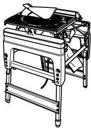
natural_image
Line drawing of a portable stove or cooking machine with a pan on top (no text or symbols)

16
006041
17
006042
18
006045
19
006046
20
006047
21
006048
22
006049
23
006050
24
006051
25
006052
26
006053
27
006054
28
006055
29
006056
30
006057

natural_image
Line drawing of a vacuum cleaner connected to a portable industrial machine (no text or symbols)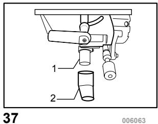

natural_image
Illustration of a hand using a tool to adjust or install a mechanical component (no text or symbols visible)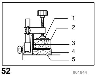

natural_image
Line drawing of a mechanical device with hands operating it, no text or symbols present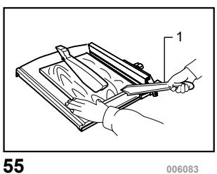
natural_image
Illustration of a hand holding a tool over a wooden board, no text or symbols present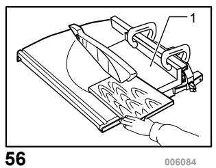
natural_image
Technical line drawing of a mechanical device with a hand operating it, no visible text or symbols
58
006086
59
006088
natural_image
Technical line drawing of a mechanical clamp or bracket (no text or symbols)60
006087
natural_image
Technical line drawing of a mechanical clamp or bracket assembly (no text or symbols)61
006089
natural_image
Technical line drawing of a mechanical device with labeled parts (no text or symbols present)62
006090
natural_image
Technical line drawing of a mechanical assembly with no visible text or symbols63
006091
64
006092
65
006093
66
001819
67
006094
natural_image
Pure mechanical diagram of a spring-loaded component with no text or symbols68
001145
69
006095
ENGLISH
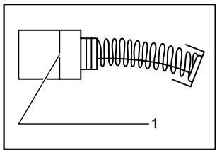
1-1. Adjusting bolt
1-2. Leg
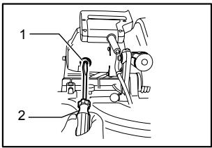
2-1. Fix plate
2-2. Hex. Bolt
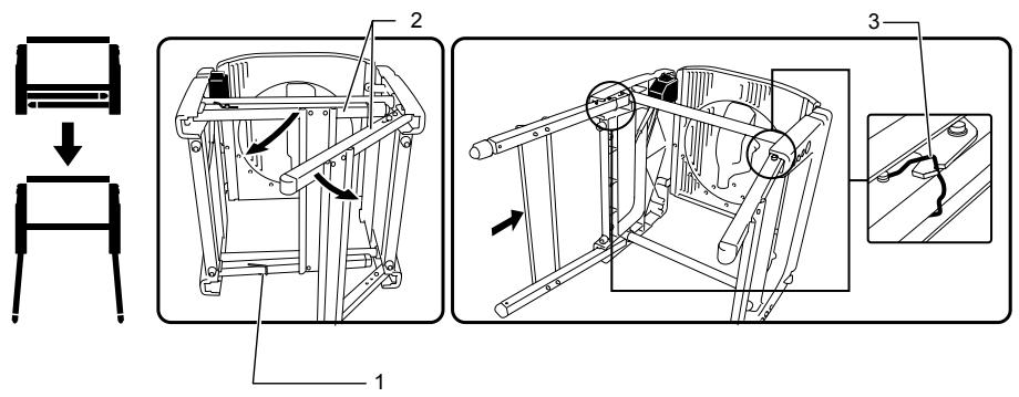
3-1. U-shaped grooves
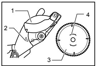
4-1. Lower blade guard A
4-2. Lower blade guard B
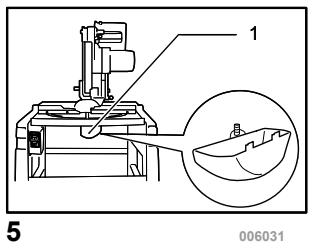
5-1. Lower blade guard A (used in the miter saw mode only)
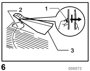
6-1.Push button
6-2. Riving knife
6-3. Top blade guard (used in the table saw mode)
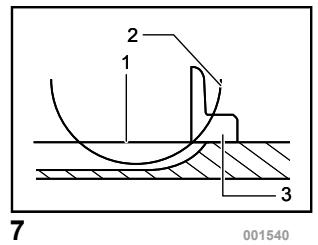
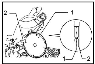
7-1. Top surface of turn base
7-2. Periphery of blade
7-3. Guide fence
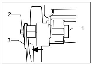
8-1. Lower limit stopper
8-2. Adjusting bolt
8-3. Nut
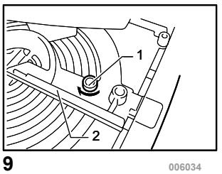
9-1. Screw
9-2. Guide fence
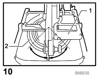
10-1. Handle
10-2. Turn table
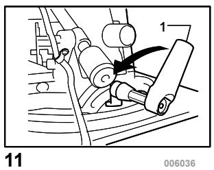
11-1. Lever
12-1. Handle
13-1. Lever
13-2. Cutting depth adjusting knob
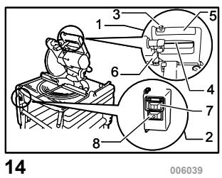
14-1. Switch in the miter saw mode
14-2. Switch in the table saw mode
14-3. Lock-off button
14-4. Switch trigger
14-5. Handle
14-6. Lever
14-7. On button
14-8. Off button
15-1. Cutting depth adjusting knob
16-1. Stopper pin
17-1. Socket wrench
17-2. Wrench holder
18-1. Socket wrench
18-2. Shaft lock
18-3. Hex. bolt
19-1. Lever
19-2. Lifting lever
20-1. Saw blade
20-2. Blade guard B
21-1. Blade case
21-2. Arrow
21-3. Saw blade
21-4. Arrow
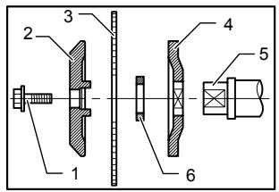
22-1. Hex. bolt
22-2. Outer flange
22-3. Saw blade
22-4. Inner flange
22-5. Spindle
Explanation of general view
22-6. Ring
23-1. Clamping nut
23-2. Hex. bolt
23-3. Riving knife
24-1. Riving knife
24-2. Saw blade
25-1. Blade width
25-2. Riving knife
25-3. Hex. bolt
26-1. Rip fence holder
26-2. Guide rail
26-3. Clamping screw (A)
26-4. Clamping screw (B)
26-5. Rip fence
27-1. Rip fence
27-2. Rip fence holder
27-3. Line to be aligned with
27-4. Saw blade
27-5. Top table
27-6. Workpiece
28-1. Rip fence
28-2. Rip fence holder
28-3. Saw blade
29-1. Rip fence
29-2. Rip fence holder
29-3. Square nut
29-4. Clamping screw (A)
29-5. Clamping screw (B)
30-1. Scale
31-1. Rip fence
31-2. Rip fence holder
31-3. Adjusting screw
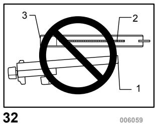
32-1. Rip fence
32-2. Saw blade
32-3. Top blade guard
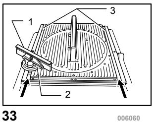
33-1. Miter gauge fence
33-2. Miter gauge
33-3. Grooves
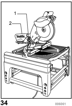
34-1. Dust nozzle
34-2. Dust bag
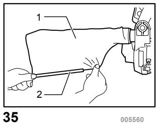
35-1. Dust bag
35-2. Fastener
37-1. Dust nozzle
37-2. Elbow
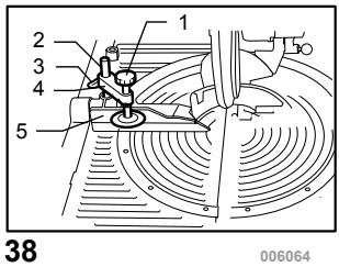
38-1. Vise arm
38-2. Vise rod
38-3. Guide fence
38-4. Vise knob
38-5. Screw
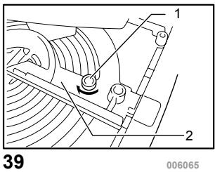
39-1. Screw
39-2. Guide fence
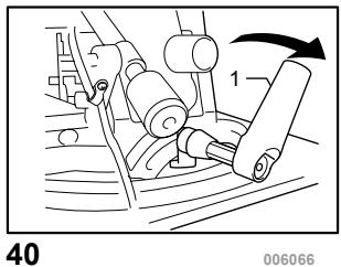
40-1. Lever
41-1. Lower limit stopper
41-2. Adjusting bolt
42-1. Screw
43-1. Stopper pin
44-1. Saw head locked in the fully lowered positon
45-1. Lever
45-2. Area of lever for hand/finger to be placed on
45-3. Hooking parts
46-1. Push button
46-2. Riving knife
46-3. Top blade guard (used in the table saw mode)
47-1. Stopper pin
48-1. Guide fence
48-2. Sub-fence R
48-3. Sub-fence L
48-4. Pin
48-5. Screw
49-1. When the sub fence is removed
49-2. When the sub fence is installed
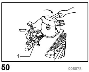
50-1. Vise (optional accessory)
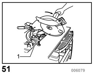
51-1. Vise (optional accessory)
52-1. Vise
52-2. Spacer block
52-3. Guide fence
52-4. Aluminum extrusion
52-5. Spacer block
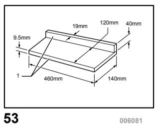
53-1. Face/edge parallel
55-1. Push stick
56-1. Auxiliary fence
57-1. Push block
57-2. Auxiliary fence
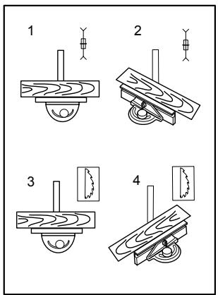
58-1. Cross cutting
58-2. Mitering
58-3. Bevel cutting
58-4. Compound mitering (angles)
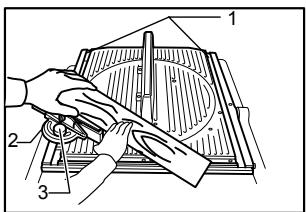
59-1. Groove
59-2. Miter gauge
59-3. Knob
61-1. Stopper pin
62-1. Tool part to be held carrying
64-1. triangular rule
64-2. Saw blade
64-3. Guide fence
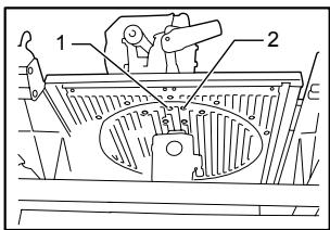
65-1. 0° adjusting bolt
65-2. 45° bevel angle adjusting bolt
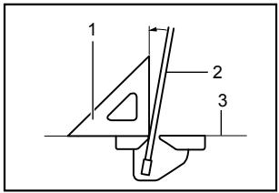
66-1. Triangular rule
66-2. Saw blade
66-3. Top surface of turn base
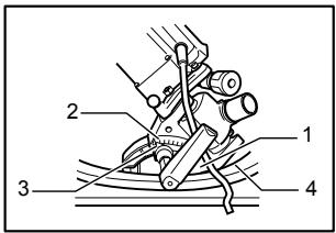
67-1. Arm
67-2. Bevel scale
67-3. Pointer
67-4. Turn base
68-1. Limit mark
69-1. Brush holder cap
SPECIFICATIONS
| Model | LF1000 |
| Blade diameter | 260 mm |
| Hole diameter | |
| For European countries | 30 mm |
Max. Cutting capacities (H x W) with blade 260 mm in diameter in the miter saw mode
| Bevel angle | Miter angle |
| 0° | |
| 0° | 20 mm x 210 mm68 mm x 155 mm |
| 45° (left) | 50 mm x 150 mm |
Max. Cutting capacities at 90^ in the table saw (bench saw mode) 70 mm
| No load speed (min ^-1 ) | 2,700 |
| Table size (W x L) | 500 mm x 555 mm |
| Dimensions (L x W x H1(note 1)/H2(note 2)) at miter saw mode | 660 mm x 650 mm x 1,220 mm / 800 mm |
| in table saw mode | 660 mm x 650 mm x 1,060 mm / 845 mm |
| Net weight | 32 kg |
| Safety class | /ll |
Note1 H1: Height up to the tool head
Note2 H2: Height up to the table
- Due to our continuing programme of research and development, the specifications herein are subject to change without notice.
- Note: Specifications may differ from country to country.
END213-4
Symbols
The following show the symbols used for the equipment. Be sure that you understand their meaning before use.


- Read instruction manual.
- DOUBLE INSULATION
- To avoid injury from flying debris, keep holding the saw head down, after making cuts, until the blade has come to a complete stop.
- Do not place hand or fingers close to the blade.
- For your safety, remove the chips, small pieces, etc. from the table top before operation.
- Unplug the tool before turning it over around the axis.
- Position hands properly when carrying.


- Do not lift up the top end of the rip fence when installing or removing it.
• Only for EU countries
Do not dispose of electric equipment together with household waste material! In observance of European Directive 2002/96/EC on waste electric and electronic equipment and its implementation in accordance with national law, electric equipment that have reached the end of their life must be collected separately and returned to an environmentally compatible recycling facility.
ENE061-1
Intended use
The tool is intended for accurate straight and miter cutting in wood. The tool can be used both in miter saw mode and in table saw mode by turning over the table around its axis.
ENF002-1
Power supply
The tool should be connected only to a power supply of the same voltage as indicated on the nameplate, and can only be operated on single-phase AC supply. They are double-insulated in accordance with European Standard and can, therefore, also be used from sockets
without earth wire.
ENG037-1
For European countries only
Noise and Vibration
The typical A-weighted noise levels are
sound pressure level: 92 dB (A)
sound power level: 105 dB (A)
Wear ear protection.
The typical weighted root mean square acceleration value is not more than 2.5 m/s^2 .
These values have been obtained according to EN61029.
ENH015-4
Model; LF1000
EC-DECLARATION OF CONFORMITY
We declare under our sole responsibility that this product is in compliance with the following standards of standardized documents;
EN61029, EN55014, EN61000 in accordance with Council Directives, 89/336/EEC, 98/37/EC.
Certificate of adequacy of the technical file with respect to 98/37/EC having been obtained from the following notified body:
Intertek SEMKO AB, Torshamnsgatan 43, Box 1103, SE-164 22 Kista, Sweden
Yasuhiko Kanzaki CE2005

000087
Director
MAKITA INTERNATIONAL EUROPE LTD.
Michigan Drive, Tongwell, Milton Keynes, Bucks MK15 8JD, ENGLAND
Responsible manufacturer:
Makita Corporation Anjo Aichi Japan
ENB094-2
ADDITIONAL SAFETY RULES FOR TOOL
FOR BOTH MITER SAW MODE AND TABLE SAW (BENCH SAW) MODE:
- Wear eye and hearing protection. Other suitable personal protective equipment should be worn.
- NEVER wear gloves during operation except for replacing saw blades or handling rough material before operation.
- Keep the floor area around the tool level well maintained and free of loose materials e.g. chips and cut-offs.
- Do not operate saw without guards and riving knife in place. Check blade guards for proper closing before each use. Do not operate saw if blade guards do not move freely and close instantly. Never clamp or tie the blade guards into the open position. Any irregular operation of the blade guards should be corrected
immediately.
-
Clean and be careful not to damage the spindle, flanges (especially the installing surface) and hex bolt before or when installing the blade. Damage to these parts could result in blade breakage. Poor installation may cause vibration/wobbling or slippage of the blade. Use only flanges specified for this tool.
-
Check the blade carefully for cracks or damage before operation. Do not use saw blade which are damaged or deformed.
-
Use only saw blades recommended by the manufacturer and which conform to EN847-1, and observe that the riving knife must not be thicker than the width of the cut by the saw blade and not thinner than the body of the blade.
-
Always use accessories recommended in this manual. Use of improper accessories such as abrasive cut-off wheels may cause an injury.
-
Select the correct saw blade for the material to be cut.
-
Do not use saw blades manufactured from high speed steel.
-
To reduce the emitted noise, always be sure that the blade is sharp and clean.
-
Use correctly sharpened saw blades. Observe the maximum speed marked on the saw blade.
-
Do not cut metal objects such as nails and screws. Inspect for and remove all nails, screws and other foreign material from the workpiece before operation.
-
Knock out any loose knots from workpiece BEFORE beginning to cut.
-
Do not use the tool in the presence of flammable liquids or gases.
-
For your safety, remove the chips, small pieces, etc. from the work area and table top before plugging the tool and starting operation.
-
The operator is adequately trained in the use, adjustment and operation of the tool.
-
Keep hands and make your bystander and yourself position out of path of and not in line with saw blade. Avoid contact with any coasting blade. It can still cause severe injury and never reach around saw blade.
-
Be alert at all times, especially during repetitive, monotonous operations. Do not be lulled into a false sense of security. Blades are extremely unforgiving.
-
Make sure the shaft lock is released before the switch is turned on.
-
Before using the tool on an actual workpiece, let it run for a while. Watch for vibration or wobbling that could indicate poor installation or a poorly balanced blade.
-
Wait until the blade attains full speed before
cutting.
-
The tool should not be used for slotting, rabbetting or grooving.
-
Refrain from removing any cut-offs or other parts of the workpiece from the cutting area whilst the tool is running and the saw head is not in the rest position.
-
Stop operation immediately if you notice anything abnormal.
-
Turn off tool and wait for saw blade to stop before moving workpiece or changing settings.
-
Unplug tool before changing blade, servicing or not in use.
-
Some dust created from operation contains chemicals known to cause cancer, birth defects or other reproductive harm. Some examples of these chemicals are:
-
lead from lead-based-painted material and,
- arsenic and chromium from chemically-treated lumber.
Your risk from these exposures varies, depending on how often you do this type of work. To reduce your exposure to these chemicals: work in a well ventilated area and work with approved safety equipment, such as those dust masks that are specially designed to filter out microscopic particles.
- Connect the tool to a dust collecting device when sawing.
- Make sure that the table is securely fixed with the lever after turning it over.
WHEN USING IN MITER SAW MODE:
- Do not use the saw to cut other than wood, aluminum or similar materials.
- Do not perform operation freehand when cutting workpiece in an area close to saw blade. The workpiece must be secured firmly against the turn table and guide fence during all operations.
- Make sure that the turn table is properly secured so it will not move during operation.
- Make sure that the arm is securely fixed when beveling. Tighten the lever clockwise to fix the arm.
- Make sure the blade does not contact the turn table in the lowest position and is not contacting the workpiece before the switch is turned on.
- Hold the handle firmly. Be aware that the saw moves up or down slightly during start-up and stopping.
WHEN USING IN THE TABLE SAW (BENCH SAW) MODE:
- Do not perform any operation freehand.
Freehand means using your hands to support or guide the workpiece, in lieu of a rip fence.
- Make sure that the turn table is fixed securely.
- Make sure that the arm is securely fixed in the working position. Tighten the lever clockwise to fix the arm.
- Use a push stick or a push block to avoid working with the hands and fingers close to the saw blade.
- Make sure the blade is not contacting the riving knife or workpiece before the switch is turned on.
- Always store the push-stick when it is not in use.
- Pay particular attention to instructions for reducing risk of KICKBACK. KICKBACK is a sudden reaction to a pinched, bound or misaligned saw blade. KICKBACK causes the ejection of the workpiece from the tool back towards the operator. KICKBACKS CAN LEAD TO SERIOUS PERSONAL INJURY. Avoid KICKBACKS by keeping the blade sharp, by keeping the rip fence parallel to the blade, by keeping the riving knife and blade guard in place and operating properly, by not releasing the workpiece until you have pushed it all the way past the blade, and by not ripping a workpiece that is twisted or warped or does not have a straight edge to guide along the fence.
- Avoid abrupt, fast feeding. Feed as slowly as possible when cutting hard workpieces. Do not bend or twist workpiece while feeding. If you stall or jam the blade in the workpiece, turn the tool off immediately. Unplug the tool. Then clear the jam.
- Before turning over the tool, always make sure that the stopper pin has securely locked the tool head in the lowest position
SAVE THESE INSTRUCTIONS.
INSTALLATION
CAUTION:
Keep the floor area around the tool level well maintained and free of loose materials such as chips and cut-offs.
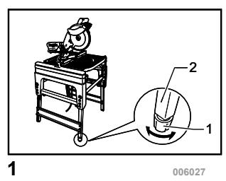
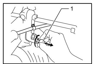
Bench mounting
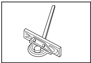
For the fully-extended feet set up as the high table When the tool cannot be set up stable, turn the adjusting nut at the foot of the tool for proper stability. Turn counterclockwise in top viewing to make the foot shorter and clockwise in top viewing to make it longer. After adjustment, make sure that the tool keep stable.
Fig.1
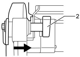
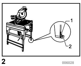
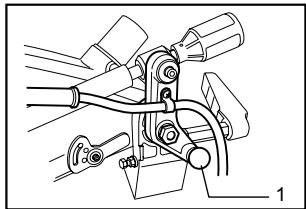
Install the fix plates with its angled end pointing outwards onto three feet of the tool with hex bolts. And secure the tool to the stable and level surface using bolt holes provided in the fix plates with three bolts.
Fig.2
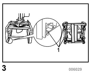
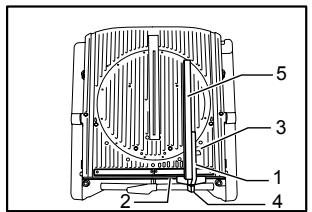
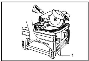
For the folded feet set up as the low table
Fig.3
When the tool is ready in the foot-folded position, secure the tool by using U-shaped grooves shown in the figure.
FUNCTIONAL DESCRIPTION
CAUTION:
- Always be sure that the tool is switched off and unplugged before adjusting or checking function on the tool.
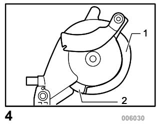
Blade guard
Fig.4
Fig.5
Fig.6
⚠️CAUTION:
• Make sure that the handle cannot be lowered without pushing the lever nearby the handle to the left.
• Make sure that the lower blade guards A dose not open unless the lever near the handle is pushed at the topmost position of the handle.
• Make sure that the lower blade guard C is installed before using in miter saw mode.
When lowering the handle while pushing the lever to the left, the lower blade guard A rises automatically. The lower blade guard B rises as it contacts a workpiece. The lower blade guards are spring loaded so it returns to its original position when the cut is completed and the handle is raised. The top blade guard falls flat on the table surface after workpiece has passed under it. NEVER DEFEAT OR REMOVE THE LOWER BLADE GUARDS, THE SPRING WHICH ATTACHES TO THE LOWER BLADE GUARD, OR THE TOP BLADE GUARD except for the note below.
In the interest of your personal safety, always maintain each blade guard in good condition. Any irregular operation of the guards should be corrected immediately. Check to assure spring loaded return action of the lower blade guards. NEVER USE THE TOOL IF THE LOWER BLADE GUARD, SPRING OR THE TOP BLADE GUARD ARE DAMAGED, FAULTY OR REMOVED except for the note below. DOING SO IS HIGHLY DANGEROUS AND CAN CAUSE SERIOUS PERSONAL INJURY.
NOTE:
• There are the following exceptions for removal of guards. Only when using in the table saw mode,
the lower blade guard C is removed. Only when using in the miter saw mode, the top blade guard is removed.
If any of these see-through blade guards becomes dirty, or sawdust adheres to it in such a way that the blade is no longer easily visible, unplug the saw and clean the guards carefully with a damp cloth. Do not use solvents or any petroleum-based cleaners on the plastic guard.
If the lower blade guard A is especially dirty and vision through the guard is impaired, proceed as follows. Raise the handle fully. Remove the saw blade (Refer to the section "Installing or removing saw blade"). Raise the lower blade guard A while pushing the lever to the left. With the lower blade guard A so positioned, cleaning can be more completely and efficiently accomplished. When cleaning is complete, reverse procedure above and secure bolt.
In the same case for the top blade guard as above stated, push in the button at its front to the surface top and remove the top blade guard. After cleaning, always reinstall it securely.
If any of these blade guards becomes discolored through age or UV light exposure, contact a Makita service center for a new guard. DO NOT DEFEAT OR REMOVE GUARDS.
Maintaining maximum cutting capacity
Fig.7
This tool is factory adjusted to provide the maximum cutting capacity for a 260 mm saw blade.
When installing a new blade, always check the lower limit position of the blade and if necessary, adjust it as follows:
⚠️CAUTION:
- When making this adjustment, unplug the tool. First, unplug the tool. Lower the handle completely. Use the wrench to turn the adjusting bolt until the periphery of the blade extends slightly below the top surface of the turn table at the point where the front face of the guide fence meets the top surface of the turn table.
With the tool unplugged, rotate the blade by hand while holding the handle all the way down to be sure that the blade does not contact any part of the lower base. Re-adjust slightly, if necessary.
CAUTION:
• After installing a new blade, always be sure that the blade does not contact any part of the lower base when the handle is lowered completely. Always do this with the tool unplugged.
This tool can be used with or without the lower limit by shifting the lower limit stopper as shown in the figure.
To use the tool without the lower limit, turn the stopper end counterclockwise. Use in this position is proper to cut a wide and thin workpiece.
To use the tool with the lower limit, move the stopper end clockwise. Use in this position is proper to cut a thick workpiece.
Fig.8
Adjusting the miter angle
Fig.9
Fig.10
Loosen the clamping screw on the guide fence by turning counterclockwise. Turn the turn table by handle. When you have moved the handle to the position where the pointer points to the desired angle on the miter scale, securely tighten the clamping screw clockwise.
CAUTION:
- When turning the turn table, be sure to raise the handle fully.
• After changing the miter angle, always secure the turn table by tightening the clamping screw firmly.
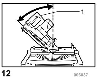
Adjusting the bevel angle
In the miter saw mode
Fig.11
Fig.12
To adjust the bevel angle, loosen the lever at the rear of the tool counterclockwise.
Push the handle to the left to tilt the saw blade until the pointer points to the desired angle on the bevel scale. Then tighten the lever clockwise firmly to secure the arm.
CAUTION:
- When tilting the saw blade, be sure to raise the handle fully.
• After changing the bevel angle, always secure the arm by tightening the lever clockwise.
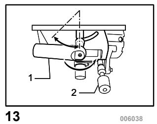
In the table saw mode
Fig.13
To adjust the bevel angle, loosen the lever under the table at the front of the tool counterclockwise.
Move the depth adjusting knob to the left to tilt the saw blade until the pointer points to the desired angle on the bevel scale. Then tighten the lever clockwise firmly to secure the arm.
Switch action
Fig.14
Switch for the miter saw mode
CAUTION:
- Before plugging in the tool, always check to see that the switch lever actuates properly and returns to the "OFF" position when released.
- When not using the tool, remove the lock-off button and store it in a secure place. This prevents unauthorized operation.
- Do not pull the switch lever hard without pressing in the lock-off button. This can cause switch breakage.
To prevent the switch lever from being accidentally pulled, a lock-off button is provided. To start the tool, push the lock lever to the left, press in the lock-off button and then pull the switch lever. Release the switch lever to stop.
Switch for the table saw mode
⚠️CAUTION:
- Before operation, make sure that the tool is turned on and off.
To start the tool, press the ON (I) button. To stop it, press the OFF (O) button.
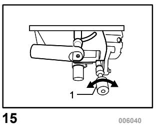
Adjusting the depth of cut
Fig.15
The depth of cut can be adjusted by turning the cutting depth adjusting knob. Turn the cutting depth adjusting knob clockwise to raise the blade or counterclockwise to lower it.
WARNING:
- Use a shallow depth setting when cutting thin materials in order to obtain a cleaner cut.
⚠️CAUTION:
- The stopper pin cannot be turned with the tool head at fully lowered position. At this time, turn the knob counterclockwise slightly and the stopper pin can be released.
Fig.16
ASSEMBLY
⚠️CAUTION:
• Always be sure that the tool is switched off and unplugged before carrying out any work on the tool.
Socket wrench storage
Fig.17
The socket wrench is stored as shown in the figure. When using the socket wrench, pull it out of the wrench holder. After using the socket wrench, return it to the wrench holder.
Table height two-way set up
The table height can be set up in two ways, high or low table.
⚠ WARNING:
- Before falling down the tool backwards, always set the tool in the miter saw mode and lock the tool head in the lowest position.
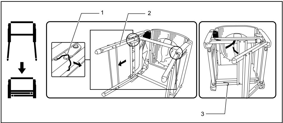
1. High table set up
- Hook
- Feet
- Stopper hook
006043
To set up the tool with high table, proceed as follows.
(1) Fall down the tool carefully BACKWARDS without fail while holding it with both hands.
(2) Turn the hook in the direction of arrow in the figure to unbundle the feet. Open the table feet on one side and push the bottom bar of the feet forward fully to be locked by itself. Take the same procedure for the feet on the
opposite side. Make sure that the feet at both sides are completely locked.
⚠ WARNING:
• Make sure that the stopper hooks are perfectly positioned in the groove of the bracket.
(3) Return the tool to the upright position.
2. Low table set up
- Stopper hook
- Feet
- Hook
006044
The feet can be folded as shown in the figure. To fold down the tool, do as follows.
(1) Fall down the tool carefully BACKWARDS without fail while holding it with both hands.
(2) Pull up first the stopper at the joint of left feet
toward yourself to unlock it
(3) Take the same steps for the opposite feet as above.
(4) Use a hook to bundle these feet.
(5) Return the tool to the upright position.
Installing or removing saw blade
CAUTION:
• Always be sure that the tool is switched off and unplugged before installing or removing the blade.
- Use only the Makita socket wrench provided to install or remove the blade. Failure to do so may result in overtightening or insufficient tightening of the hex bolt. This could cause an injury.
Move up the handle in the fully raised position.
Press the shaft lock to lock the spindle, use the socket wrench to loosen the hex bolt clockwise.
Fig.18
Raise the blade guard A with its lifting lever while pushing the lever nearby the handle to the left. With the blade guard A raised, remove the hex bolt, outer flange and blade.
Fig.19
To install the blade, mount it carefully onto the spindle, making sure that the direction of the arrow on the surface of the blade matches the direction of the arrow on the blade case. Install the outer flange and hex bolt, and then use the socket wrench to tighten the hex bolt (left-handed) securely counterclockwise while pressing the shaft lock.
Fig.20
Fig.21
NOTE:
- When installing a saw blade, be sure to insert it between the blade guard B at first and then raise it so that the blade is finally placed in the blade guard B.
For all countries other than European countries
Fig.22
⚠️CAUTION:
- The silver ring 25.4 mm in outer diameter is factory-installed onto the spindle. The black ring 25 mm in outer diameter is included as standard equipment. Before mounting the blade onto the spindle, always be sure that the correct ring for the arbor hole of the blade you intend to use is installed onto the spindle.
For European countries
CAUTION:
- The ring 30 mm in outer diameter is factory-installed between the inner and outer flanges.
Return the lower blade guard A to its original position. Lower the handle to make sure that the lower blade guards move properly. Make sure shaft lock has released spindle before making cut.
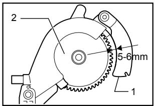
Adjusting riving knife
Fig.23
There must be a clearance of about 5 - 6 mm between the riving knife and the blade teeth when pushing the riving knife toward the blade fully. Adjust the riving knife accordingly by first loosening clamping nut by hand counterclockwise and then loosening hex bolt counterclockwise with the hex socket wrench, and measuring the distance. After adjustment, securely tighten the hex bolt and then the clamping nut clockwise. Always check to see that the riving knife is secured and that the top blade guard works smoothly before cutting.
Fig.24
The riving knife has been installed before shipment from the factory so that the blade and riving knife are in a straight line after your simple set-up. Refer to the section titled "Repositioning riving knife" for the set-up.
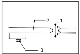
Fig.25
⚠️CAUTION:
- If the blade and riving knife are not aligned properly, a dangerous pinching condition may result during operation. Make sure the riving knife is positioned between both outer ends of the blade teeth when viewing from the top. You could suffer serious personal injury while using the tool without a properly aligned riving knife. If they are not aligned for any reasons, always have Makita authorized service center repair it.
- When adjusting the riving knife clearance from the blade teeth, always loosen the hex bolt only after loosening the clamping nut.
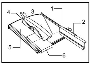
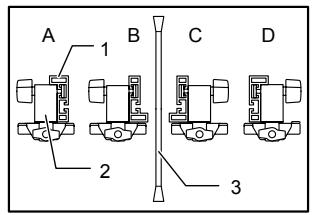
Installing and adjusting rip fence
Fig.26
- Install the rip fence on the table so that the rip fence holder engages with the guide rail. Tighten the clamping screw (B) of the rip fence firmly clockwise.
- Loosen the clamping screw (A).
- Slide the rip fence and secure it so that the far end from you of the rip fence is aligned with the point at which the front edge of saw blade just appears from top surface of the workpiece. The purpose of this adjustment is to reduce risk of kick-back toward operator that cut piece from the workpiece is pinched between the saw blade and rip fence and finally pushed out toward operator. The line (A) varies by thickness of workpiece or the table level. Adjust the position of the rip fence according to the thickness of the workpiece.
After adjusting the rip fence, tighten the clamping screw (A) firmly.
Fig.27
NOTE:
- There are four patterns to position the rip fence as shown in the figure. Rip fence has two slits on its sides, one slit with an elevated fringe nearby on the same side and the other without it. Use the surface of rip fence with this fringe facing the workpiece only when cutting off into a piece of a thin workpiece.
Fig.28
NOTE:
- To change the rip fence pattern, remove the rip fence from the rip fence holder by loosening the clamping screw (A) and change the facing of the rip fence to the rip fence holder so that the rip fence faces the rip fence holder according to your work as shown in the figure.
Insert the square nut on the rip fence holder into the back end of either slit of the rip fence so that they fit as shown in the figure..
To change from the pattern A or B to the pattern C or D, or in adverse case, remove the square nut and clamping screw (A) from the rip fence holder, then position the clamping screw (A) and square nut on the opposite position of the rip fence holder compared to the original position Tighten the clamping screw (A) securely after inserting the square nut of the rip fence holder into the rip fence slit.
Insert the square nut on the rip fence holder into the back end of either slit of the rip fence so that they fit as shown in the figure..
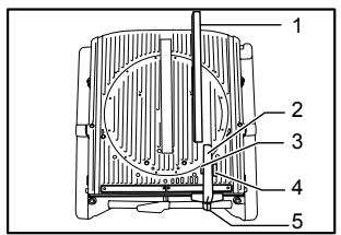
Fig.29
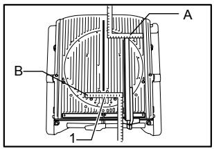
The rip fence is factory adjusted so that it is parallel to the blade surface. Make sure that it is parallel. To check to be sure that the rip fence is parallel with the blade, adjust the blade height with the cutting depth adjusting knob so that the blade appears at the topmost position from the table. Mark one of the blade teeth with a crayon. Measure the distance (A) and (B) between the rip fence and blade. Take both measurements using the tooth marked with the crayon. These two measurements should be identical If the rip fence is not parallel with the blade, proceed as follows:
Fig.30
(1) Turn the adjusting screw counterclockwise.
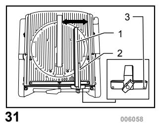
Fig.31
Fig.32
(2) Shift the front edge of the rip fence slightly to right or left until it becomes parallel with the blade.
(3) Tighten the adjusting screw on the rip fence firmly.
⚠️CAUTION:
- Be sure to adjust the rip fence so that it is parallel with the blade, or a dangerous kickback condition may occur.
- Be sure to adjust the rip fence so that it does not contact the top blade guard or saw blade.
• Do not relocate or carry the tool by rip fence. - Raising the installed rip fence or exerting a force on it to the right and left with your hand grabbing its top end may damage it and impair its function.
Installing and adjusting miter gauge
Fig.33
Install the miter gauge by inserting its shaft into one of two grooves in the table from the front. Miter gauge fence that is also used as rip fence can be installed on the miter gauge according to your work.
Dust bag
Fig.34
The use of the dust bag makes cutting operations clean and dust collection easy. To attach the dust bag, fit it onto the dust nozzle.
When the dust bag is about half full, remove the dust bag from the tool and pull the fastener out. Empty the dust bag of its contents, tapping it lightly so as to remove particles adhering to the insides which might hamper further collection.
Fig.35
If you connect a vacuum cleaner to your saw, more efficient and cleaner operations can be performed.
Fig.36
Elbow
Fig.37
CAUTION:
- Point the discharge opening of the elbow to the direction in which the exhaust dust and chips do not fly out toward the tool and persons in work area.
Attach the elbow when changing the direction of dust discharge.
Securing workpiece
⚠ WARNING:
- It is extremely important to always secure the workpiece properly and tightly with the vise. Failure to do so can cause the tool to be damaged and/or the workpiece to be destroyed. PERSONAL INJURY MAY ALSO RESULT. Also, after a cutting operation, DO NOT raise the blade until the blade has come to a complete stop.
Vertical vise
Fig.38
The vertical vise can be installed in two positions on either the left or right side of the guide fence. Insert the vise rod into the hole in the guide fence and tighten the
clamping screw to secure the vise rod.
Position the vise arm according to the thickness and shape of the workpiece and secure the vise arm by tightening the clamping screw. If the screw to secure the vise arm contacts the guide fence, install the clamping screw on the opposite side of vise arm. Make sure that no part of the tool contacts the vise when lowering the handle all the way. If some part contacts the vise, re-position the vise.
Press the workpiece flat against the guide fence and the turn table. Position the workpiece at the desired cutting position and secure it firmly by tightening the vise knob.
CAUTION:
- The workpiece must be secured firmly against the turn table and guide fence.
Setting up the tool in table saw mode
CAUTION:
- Before use in the table saw mode, make sure that the turn table has been secured at 0° miter angle with the clamping screw on the guide fence.
- Before use in the table saw mode, make sure that the tool head has been secured with the lever.
• Before use in the table saw mode, make sure that the riving knife has been secured in place properly.
- Before use in the table saw mode, remove the lower blade guard C.
- In table saw mode, release the lower limit stopper. The tool is shipped from the factory with the set-up in miter saw mode. Before use in table saw mode, change the set up and follow the procedure below.
1. Securing the turn table
Fig.39
To secure the turn table, tighten the clamping screw firmly on the guide fence at 0^ miter angle.
2. Securing the tool head
Fig.40
Secure the tool head by tightening the lever in the direction of arrow shown in the figure.
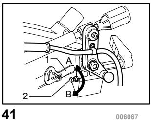
3. Releasing the lower limit stopper
Fig.41
Make sure that the end of the lower limit stopper is at the A position in the figure. Turn the end of the lower limit stopper counterclockwise to the A position when it is positioned at the B position.
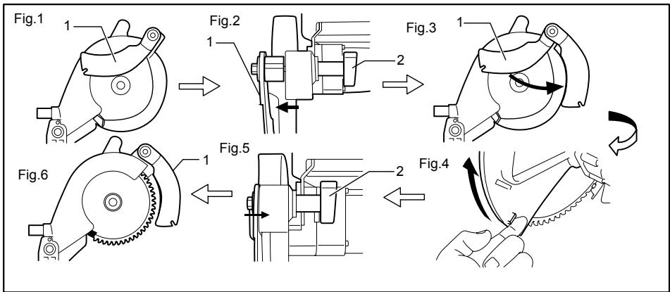
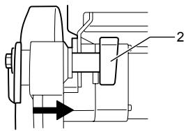
4. Repositioning the riving knife
flowchart
graph TD
    A["Step 1: Initial mechanical component"] --> B["Step 2: Component with two arms"]
    B --> C["Step 3: Component with two arms"]
    C --> D["Step 4: Tool being cut"]
    D --> E["Step 5: Component with two arms"]
    E --> F["Step 6: Tool being cut"]
- Riving knife
- Clamping nut
006068
The position (Fig. 1) should be changed as follows.
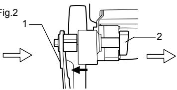
(1) Loosen the clamping nut (Fig. 2).
(2) Pull and pivot the riving knife to the position at the angle of 90^ in the direction of arrow (Fig. 3). And push in it slightly so that it become still in this position.
(3) Raise the lower blade guard A fully using its lug by hand while pushing the lever nearby the handle to the left, and release the lever nearby the handle (Fig. 4).
(4) Push the riving knife in the direction of arrow (see Fig. 5) so that it is aligned with the saw blade.
(5) After pushing the riving knife in the direction of arrow shown in the figure, release the lower blade guard A.
(6) After aligning the riving knife, tighten the clamping nut securely (see Fig. 6)
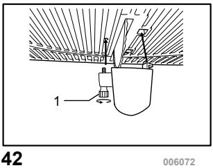
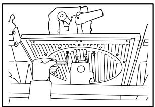
5. Removing the lower blade guard C
Fig.42
Remove the lower blade guard C from the table by loosening the clamping screw.
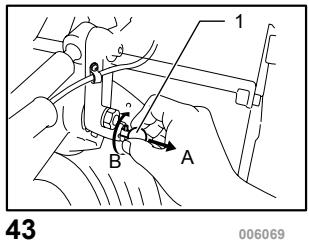
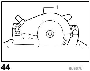
6. Locking the tool head at fully lowered position
Fig.43
Fig.44
After setting up the riving knife in position for
table saw mode, pull the stopper in the direction of arrow A and turn it to the angle of 90^ in the direction of arrow B with the stopper pulled. Then lower the handle to lock the tool head.
CAUTION:
- When the tool head cannot be locked in the fully lowered position, turn the depth adjusting knob by several turns clockwise.
- Before turning over the tool, always make sure that the stopper pin has securely locked the tool head in the lowest position.
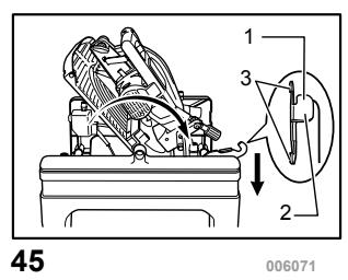
7. Turning over the tool
⚠ WARNING:
• Make sure that the tool is switched off and unplugged before turning over.
- When pushing down the lever, be sure to place your hand/finger away from the lever-table fitting area.
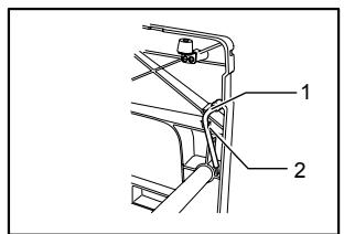
Fig.45
Hold the middle edge of table with one hand, push the lever down with the other hand while holding the table edge firmly and pivot the table carefully to turn it over. Keep holding it until it locks.
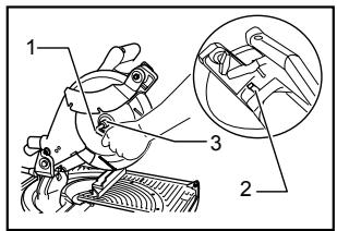
8. Installing the top blade guard
Fig.46
Push the push button of the top blade guard to its side surface, place it on the notch of the riving knife with the button depressed and release the button. After releasing the push button, make sure that the top blade guard is secured by trying to pull it out.
⚠️CAUTION:
• After installing the top blade guard, make sure that it works smoothly.
Setting up the tool in miter saw mode
⚠ WARNING:
- Be sure to install the lower blade guard C before using the tool in miter saw mode.
To change the set up from table saw mode to miter saw mode, reverse the procedure of the section titled "Setting up the tool in table saw mode"
1. Removing the top blade guard
Push the push button of the top blade guard to its side surface and then just take away the top blade guard upward with the button depressed.
2. Installing the lower blade guard C
Place the lower blade guard C on the table so that it fits in the slot of the table and tightening the clamping screw firmly.
3. Turning over the tool
Refer to the same titled section in the "Setting up the tool in table saw mode".
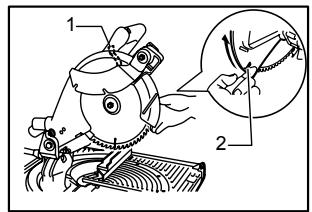
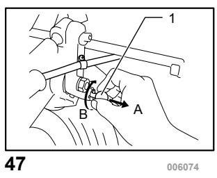
4. Releasing the tool head from fully lowered position
Fig.47
While holding the handle, pull the stopper pin in the direction of arrow A, turn it to the angle of 90^ in the direction of arrow B with the stopper pin pulled and then raise the handle slowly.
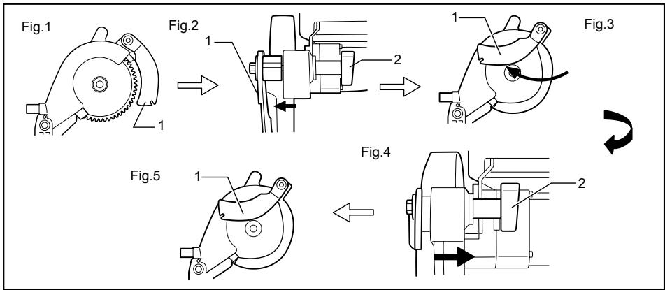
5. Repositioning riving knife
flowchart
graph TD
    A["Fig.1"] --> B["Step 1: Rotation of mechanical component"]
    B --> C["Step 2: Rotation of motor assembly"]
    C --> D["Step 3: Rotation of motor assembly"]
    D --> E["Step 4: Rotation of motor assembly"]
    E --> F["Step 5: Rotation of motor assembly"]
- Riving knife
- Clamping nut
006075
The position of riving knife (Fig. 1) should be changed as follows.
(1) Loosen the clamping nut and hold the lower blade guard A using its lug by hand (Fig. 2).
(2) While holding the lower blade guard A, pull the riving knife so that it turns and pivot it to the position in the direction of arrow (Fig. 3).
(3) With the riving knife held in that position, return the lower blade guard A to the original
position and tighten the clamping nut securely (Fig. 4, 5).
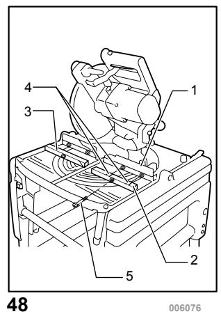
6. Installing or removing the sub fences R and L Fig.48
⚠️CAUTION:
- When cutting a workpiece over 20 mm thick, make sure that the sub fences R and L are securely installed with a screw.
Removal of the sub fences R and L are convenient for cutting wide and thin workpiece.
When cutting a workpiece up to 20 mm thick and more than 180 mm wide, remove the sub fences R and L by removing the screw shown in the figure.
When cutting a workpiece over 20 mm thick, install the sub fences R and L securely with a screw.
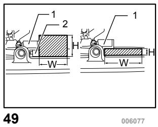
Refer to the table below for the relation between the size of workpiece and use/unuse of sub fences R and L.
Fig.49
| Workpiece size (H x W) | use/unuse of sub fences | |
| 1 | 68 mm x 155 mm | with sub fences |
| 2 | 20 mm x 210 mm | without sub fences |
006577
OPERATION
CAUTION:
- Before use, be sure to release the handle from the lowered position by pulling the stopper pin and turning it to the angle of 90^ .
• Make sure the blade is not contacting the workpiece, etc. before the switch is turned on.
CUTTING AS MITER SAW
⚠ WARNING:
• Make sure that the lower blade guard C is installed before using in miter saw mode.
CAUTION:
- Do not apply excessive pressure on the handle when cutting. Too much force may result in overload of the motor and/or decreased cutting efficiency. Push down handle with only as much force as is necessary for smooth cutting and without significant decrease in blade speed.
- Gently press down the handle to perform the cut. If the handle is pressed down with force or if lateral force is applied, the blade will vibrate and leave a mark (saw mark) in the workpiece and the precision of the cut will be impaired.
1. Press cutting
Fig.50
Secure the workpiece against guide fence and turn table. Switch on the tool without the blade making any contact and wait until the blade attains full speed before lowering. Then gently lower the handle to the fully lowered position to cut the
workpiece. When the cut is completed, switch off the tool and WAIT UNTIL THE BLADE HAS COME TO A COMPLETE STOP before returning the blade to its fully elevated position.
2. Miter cutting
Refer to the previously covered "Adjusting the miter angle".
3. Bevel cut
Fig.51
Loosen the lever and tilt the saw blade to set the bevel angle (Refer to the previously covered "Adjusting the bevel angle"). Be sure to retighten the lever firmly to secure the selected bevel angle safely. Secure the workpiece against guide fence and turn table. Switch on the tool without the blade making any contact and wait until the blade attains full speed. Then gently lower the handle to the fully lowered position while applying pressure in parallel with the blade. When the cut is completed, switch off the tool and WAIT UNTIL THE BLADE HAS COME TO A COMPLETE STOP before returning the blade to its fully elevated position.
⚠️CAUTION:
• Always be sure that the blade will move down to bevel direction during a bevel cut. Keep hands out of path of saw blade.
- During a bevel cut, it may create a condition whereby the piece cut off will come to rest against the side of the blade. If the blade is raised while the blade is still rotating, this piece may be caught by the blade, causing fragments to be scattered which is dangerous. The blade should be raised ONLY after the blade has come to a complete stop.
- When pressing the handle down, apply pressure parallel to the blade. If the pressure is not parallel to the blade during a cut, the angle of the blade might be shifted and the precision of the cut will be impaired.
4. Compound cutting
Compound cutting is the process in which a bevel angle is made at the same time in which a miter angle is being cut on a workpiece. Compound cutting can be performed at angle shown in the table.
| Bevel angle | Miter angle |
| 45° | Left and Right 0° - 45° |
006366
When performing compound cutting, refer to "Press cutting", "Miter cutting" and "Bevel cut" explanations.
5. Cutting aluminum extrusion
Fig.52
When securing aluminum extrusions, use spacer blocks or pieces of scrap as shown in the figure to prevent deformation of the aluminum. Use a cutting lubricant when cutting the aluminum
extrusion to prevent build-up of the aluminum material on the blade.
⚠️CAUTION:
- Never attempt to cut thick or round aluminum extrusions. Thick aluminum extrusions may come loose during operation and round aluminum extrusions cannot be secured firmly with this tool.
- Never cut aluminum in the table saw mode (bench mode).
CUTTING AS TABLE SAW (BENCH MODE)
CAUTION:
• Always use "work helpers" such as push sticks and push blocks when there is a danger that your hands or fingers will come close to the blade.
• Always hold the workpiece firmly with the table and the rip fence. Do not bend or twist it while feeding. If the workpiece is bent or twisted, dangerous kickbacks may occur.
- NEVER withdraw the workpiece while the blade is running. If you must withdraw the workpiece before completing a cut, first switch the tool off while holding the workpiece firmly. Wait until the blade has come to a complete stop before withdrawing the workpiece. Failure to do so may cause dangerous kickbacks.
- NEVER remove cut-off material while the blade is running.
• NEVER place your hands or fingers in the path of the saw blade.
• Always secure the rip fence firmly, or dangerous kickbacks may occur.
- Always use "work helpers" such as push sticks and push blocks when cutting small or narrow workpieces, or when the is hidden from view while cutting.
Work helpers
Push sticks, push blocks or auxiliary fence are types of "work helpers". Use them to make safe, sure cuts without the need for the operator to contact the blade with any part of the body.
Push block
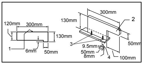
- Face/edge parallel
- handle
- Wood screw
- Guide together
006080
Use a 19 mm piece of plywood.
Handle should be in center of plywood piece. Fasten with glue and wood screws as shown. Small piece 9.5 mm x 8 mm x 50 mm of wood must always be glued to plywood to keep the blade from dulling if the operator cuts into push block by mistake. (Never use nails in push block.)
Auxiliary fence
Fig.53
Make auxiliary fence from 9.5 mm and 19 mm plywood pieces.
Ripping
⚠️CAUTION:
- When ripping, remove the miter gauge from the table.
-
When cutting long or large workpieces, always provide adequate support behind the table. DO NOT allow a long board to move or shift on the table. This will cause the blade to bind and increase the possibility of kickback and personal injury. The support should be at the same height as the table.
-
Adjust the depth of cut a bit higher than the thickness of the workpiece. To make this adjustment, refer to the section titled "Adjusting the depth of cut".
- Position the rip fence to the desired width of rip and secure in place by tightening the clamping screw (A). Before ripping, make sure the two screws of the rip fence holder are secured. If it is not secured enough, retighten it.
- Turn the tool on and gently feed the workpiece into the blade along with the rip fence.
(1) When the width of rip is 150 mm and wider, carefully use one hand to feed the workpiece. Use another hand to hold the workpiece in position against the rip fence.
Fig.54
(2) When the width of rip is 65 mm - 150 mm wide, use the push stick to feed the workpiece.
Fig.55
(3) When the width of rip is narrower than 65 mm, the push stick cannot be used because the push stick will strike the blade guard. Use the auxiliary fence and push block.
Attach the auxiliary fence to the rip fence with two "C" clamps.
Fig.56
Feed the workpiece by hand until the end is about 25 mm from the front edge of the top table. Continue to feed using the push block on the top of the auxiliary fence until the cut is complete.
Fig.57 Cross cutting
CAUTION:
- When making a crosscut, remove the rip fence from the table.
- When cutting long or large workpieces, always provide adequate support to the sides of the table. The support should be at the same height as the table.
• Always keep hands away from the path of blade.
Miter gauge
Use the miter gauge for the 4 types of cutting shown in the figure.
Fig.58
⚠️CAUTION:
- Secure the knob on the miter gauge carefully.
- Avoid creep of workpiece and gauge by firm work-holding arrangement, especially when cutting at an angle.
- NEVER hold or grasp the intended "cut-off" portion of the workpiece.
Use of miter gauge
Fig.59
Slide the miter gauge into the thick grooves in the table. Loosen the knob on the gauge and align to desired angle ( 0^ to 60^ ). Bring stock flush up against fence and feed gently forward into the blade.
Auxiliary wood facing (miter gauge)
Fig.60
To prevent a long board from wobbling, fit the miter gauge with an auxiliary fence board. Fasten with bolts/nuts after drilling holes, but fasteners must not protrude from the face board.
Carrying tool
Fig.61
Make sure that the tool is unplugged. For the tool just used in the miter saw mode, secure the blade at 0^ bevel angle and the turn table at 0^ miter angle. Lower the handle fully and lock it in the lowered position by fully pushing in the stopper pin.
Carry the tool by holding the tool part shown in the figure.
Fig.62
⚠️CAUTION:
• Always secure all moving portions before carrying the tool.
- Before carrying the tool, always set up the tool in the miter saw mode.
• Make sure that the lower blade guard C is installed on the tool.
MAINTENANCE
⚠️CAUTION:
• Always be sure that the tool is switched off and unplugged before attempting to perform inspection or maintenance.
⚠ WARNING:
• Always be sure that the blade is sharp and clean for the best and safest performance.
Adjusting the cutting angle
This tool is carefully adjusted and aligned at the factory, but rough handling may have affected the alignment. If your tool is not aligned properly, perform the following:
1. Miter angle
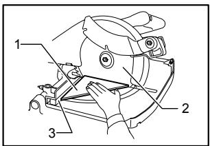
Fig.63
Miter angle 0^ adjusting bolts are located in four positions.
Loosen four miter angle 0^ adjusting bolts by turning counterclockwise from the underside of the table.
Lower the handle fully and lock it in the lowered position by pulling and rotating the stopper pin to the angle of 90^ clockwise. Square the side of the blade with the face of the guide fence using a triangular rule, try-square, etc. Then securely tighten the four adjusting bolts on the sub arm from the underside of the table. Make sure that the pointer points to 0^ on the miter scale. If not so, adjust the pointer position by loosening the screw securing the pointer. After adjusting it, securely tighten the screw.
Fig.64
2. Bevel angle
Fig.65
(1) 0° bevel angle Lower the handle fully and lock it in the lowered position by pulling and rotating the stopper pin to the angle of 90° clockwise. Loosen the lever at the rear of the tool. Turn, from the underside of the table, the 0° bevel angle adjusting bolt on the right side of the sub arm two or three revolutions counterclockwise to tilt the blade to the right. Carefully square the side of the blade with the top surface of the turn table using the triangular rule, try-square, etc. by turning the 0° bevel angle adjusting bolt clockwise.
Fig.66
Make sure that the pointer on the turn table point to 0^ on the bevel scale on the arm. If it does not point to 0^ , loosen the screw which secures the pointer and adjust the pointer so that it will point to 0^ .
Fig.67
(2) 45^ bevel angle
Adjust the 45^ bevel angle only after performing 0^ bevel angle adjustment. To adjust left 45^ bevel angle, loosen the lever and tilt the blade to the left fully. Make sure that the pointer on the arm points to 45^ on the bevel scale on the arm. If the pointer does not point to 45^ , turn, from the underside of the table, the 45^ bevel angle adjusting bolt on the left side of the sub arm until the pointer points to 45^ .
Replacing carbon brushes
Fig.68
Remove and check the carbon brushes regularly. Replace when they wear down to the limit mark. Keep the carbon brushes clean and free to slip in the holders. Both carbon brushes should be replaced at the same time. Use only identical carbon brushes.
Use a screwdriver to remove the brush holder caps. Take out the worn carbon brushes, insert the new ones and secure the brush holder caps.
Fig.69
After use
- After use, wipe off chips and dust adhering to the tool with a cloth or the like to assure maximum service life. Keep the blade guards clean according to the directions in the previously covered section titled "Blade guard". Lubricate the sliding portions with machine oil to prevent rust.
To maintain product SAFETY and RELIABILITY, repairs, any other maintenance or adjustment should be performed by Makita Authorized Service Centers, always using Makita replacement parts.
ACCESSORIES
⚠️CAUTION:
- These accessories or attachments are recommended for use with your Makita tool specified in this manual. The use of any other accessories or attachments might present a risk of injury to persons. Only use accessory or attachment for its stated purpose.
If you need any assistance for more details regarding these accessories, ask your local Makita Service Center.
• Steel & Carbide-tipped saw blades
- Vertical vise
- Socket wrench 13-3
- Dust bag
- Triangular rule
• Dust cover (Lower blade guard C)
- Push stick
• Ruler assembly (Rip fence)
- Miter gauge
• Fix plates (3 pieces)
• Hex bolts (3 pieces)
- Elbow
• Top cover assy (Top blade guard)
УКРАЇНСЬКА
flowchart
graph TD
    A["Step 1: Initial mechanical component"] --> B["Step 2: Component assembly with two parts"]
    B --> C["Step 3: Final assembly with two parts"]
    C --> D["Step 4: Tool being cut off"]
    D --> E["Step 5: Final assembly with two parts"]
    E --> F["Step 6: Final assembly with one part"]
natural_image
Technical line drawing of a mechanical gear assembly (no text or symbols)Fig.2
Michigan Drive, Tongwell, Milton Keynes, Bucks MK15 8JD, ENGLAND (ANGLIA)
DLA TRYBU PIŁY STOŁOWEJ I PIŁY
GRZBIETNICOWEJ
natural_image
Technical line drawing of a mechanical gear assembly (no text or symbols)Fig.2

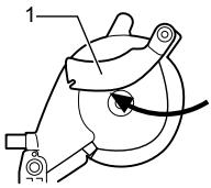
Fig.3

Fig.5

Fig.4

Michigan Drive, Tongwell, Milton Keynes, Bucks MK15 8JD, ANGLIA
Producător:
Makita Corporation Anjo Aichi Japan
ENB094-2
NORME SUPLIMENTARE DE SECURITATE PENTRU MAŞINĂ
PENTRU AMBELE MODURI DE UTILIZARE, CA FERĂSTRĂU PENTRU TĂIERI OBLICE ȘI CA FERĂSTRĂU CIRCULAR CU MASĂ (DE BANC):
LA UTILIZAREA ÎN MODUL FERĂSTRĂU CIRCULAR CU MASĂ (DE BANC):
flowchart
graph TD
    A["Step 1: Initial mechanical component"] --> B["Step 2: Component with two arms"]
    B --> C["Step 3: Component with two arms"]
    C --> D["Step 4: Tool being cut"]
    D --> E["Step 5: Component with two arms"]
    E --> F["Step 6: Tool being cut"]
flowchart
graph TD
    A["Fig.1"] --> B["Step 1: Rotation of mechanical component"]
    B --> C["Step 2: Rotation of mechanical component"]
    C --> D["Step 3: Rotation of mechanical component"]
    D --> E["Step 4: Rotation of mechanical component"]
    E --> F["Step 5: Rotation of mechanical component"]
Michigan Drive, Tongwell, Milton Keynes, Bucks MK15 8JD, ENGLAND
flowchart
graph TD
    A["Step 1: Initial mechanical component"] --> B["Step 2: Internal mechanism with two numbered components"]
    B --> C["Step 3: Internal mechanism with two numbered components"]
    C --> D["Step 4: Tool being cut off"]
    D --> E["Step 5: Internal mechanism with two numbered components"]
    E --> F["Step 6: Tool being cut off"]
natural_image
Technical line drawing of a mechanical gear assembly (no text or symbols)Fig.2

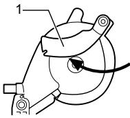
Fig.3

Fig.5

Fig.4


1. Spaltkeil
Michigan Drive, Tongwell, Milton Keynes, Bucks MK15 8JD, ENGLAND
Felelős gyártó:
Makita Corporation Anjo Aichi Japan
ENB094-2
KIEGÉSZÍTŐ BIZTONSÁGI ELŐÍRÁSOK A SZERSZÁMRA VONATKOZÓAN
flowchart
graph TD
    A["Step 1: Initial mechanical component"] --> B["Step 2: Component with two parts"]
    B --> C["Step 3: Component with two parts"]
    C --> D["Step 4: Tool being cut"]
    D --> E["Step 5: Component with two parts"]
    E --> F["Step 6: Tool being cut"]
flowchart
graph TD
    A["Fig.1"] --> B["Step 1: Rotation of mechanical component"]
    B --> C["Step 2: Rotation of motor assembly"]
    C --> D["Step 3: Rotation of motor assembly"]
    D --> E["Step 4: Rotation of motor assembly"]
    E --> F["Step 5: Rotation of motor assembly"]
Michigan Drive, Tongwell, Milton Keynes, Bucks MK15 8JD, ANGLICKO
Zodpovedný výrobca:
Makita Corporation Anjo Aichi Japan
ENB094-2
ĎALŠIE BEZPEČNOSNÉ ZÁSADY PRE NÁSTROJ
PRE REŽIM PÍLY NA ZREZÁVANIE AJ STOLOVEJ PÍLY (PLOŠINOVEJ PÍLY):
TIETO POKYNY USCHOVAJTE.
INŠTALÁCIA
⚠POZOR:
flowchart
graph TD
    A["Step 1: Initial mechanical component"] --> B["Step 2: Internal mechanism with two arms"]
    B --> C["Step 3: Internal mechanism with two arms"]
    C --> D["Step 4: Tool being cut off"]
    D --> E["Step 5: Internal mechanism with two arms"]
    E --> F["Step 6: Tool being cut off"]
- Štiepiaci nôž
- Upínacia matica
006068
natural_image
Mechanical gear assembly diagram labeled Fig.1, showing meshing gears and mounting points (no text or symbols beyond label)Fig.2
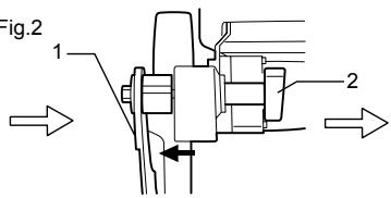
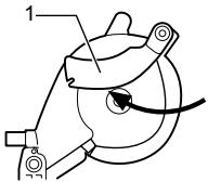
Fig.3

Fig.5
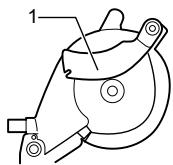
Fig.4


1. Štiepiaci nôž
2. Upínacia matica
006075
Michigan Drive, Tongwell, Milton Keynes, Bucks MK15 8JD, ANGLIE
Odpovědný výrobce:
Makita Corporation Anjo Aichi Japan
ENB094-2
DOPLŇKOVÁ BEZPEČNOSTNÍ PRAVIDLA PRO NÁSTROJ
PRO REŽIM POKOSOVÉ PILY I STOLNÍ PILY:
POUŽITÍ V REŽIMU STOLNÍ PILY:
TYTO POKYNY USCHOVEJTE.
INSTALACE
⚠POZOR:
flowchart
graph TD
    A["Step 1: Initial mechanical component"] --> B["Step 2: Component with two arms"]
    B --> C["Step 3: Component with two arms"]
    C --> D["Step 4: Tool being cut off"]
    D --> E["Step 5: Component with two arms"]
    E --> F["Step 6: Tool being cut off"]
natural_image
Technical line drawing of a mechanical gear assembly (no text or symbols)Fig.2
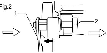
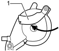
Fig.3

Fig.5

Fig.4