
2702X1 - Table saw MAKITA - Free user manual and instructions
Find the device manual for free 2702X1 MAKITA in PDF.

| Product Type | Table Saw |
| Brand | MAKITA |
| Model | 2702X1 |
| Power Supply | 120 V, 60 Hz |
| Blade Diameter | 250 mm (10 in) |
| Cutting Capacity | Adjustable depth; angle from 0° to 45° |
| No-Load Speed | Not specified (estimate: 3,000 – 4,000 RPM) |
| Weight | Approximately 25 kg (estimate) |
| Table Dimensions | Approximately 550 x 450 mm (estimate) |
| Safety | Blade guard, splitter, anti-kickback pawls, key switch |
| Included Accessories | Miter gauge, rip fence, wrenches, saw stand |
| Maintenance | Lubrication of moving parts; brush replacement |
| Spare Parts | Carbon brushes, flanges, nuts, Dado set (ref. 191543-4) |
| Repairability | Repairs by Makita authorized service center; use of genuine parts |
| Warranty | 1 year (parts and labor) |
Frequently Asked Questions - 2702X1 MAKITA
User questions about 2702X1 MAKITA
0 question about this device. Answer the ones you know or ask your own.
Ask a new question about this device
Download the instructions for your Table saw in PDF format for free! Find your manual 2702X1 - MAKITA and take your electronic device back in hand. On this page are published all the documents necessary for the use of your device. 2702X1 by MAKITA.
USER MANUAL 2702X1 MAKITA
MANUEL D'INSTRUCTION
For your personal safety, READ and UNDERSTAND before using.
SAVE THESE INSTRUCTIONS FOR FUTURE REFERENCE.
AVERTISSEMENT:
- Due to our continuing programme of research and development, the specifications herein are subject to change without notice.
Note: Specifications may differ from country to country.
For Your Own Safety Read Instruction Manual Before Operating Tool Save it for future reference GENERAL SAFETY PRECAUTIONS
USA007-2
(For All Tools)
- KNOW YOUR POWER TOOL. Read the owner's manual carefully. Learn the tool's applications and limitations, as well as the specific potential hazards peculiar to it.
- KEEP GUARDS IN PLACE and in working order.
- REMOVE ADJUSTING KEYS AND WRENCHES. Form habit of checking to see that keys and adjusting wrenches are removed from tool before turning it on.
- KEEP WORK AREA CLEAN. Cluttered areas and benches invite accidents.
- DON'T USE IN DANGEROUS ENVIRONMENT. Don't use power tools in damp or wet locations, or expose them to rain. Keep work area well lighted. Don't use tool in presence of flammable liquids or gases.
- KEEP CHILDREN AWAY. All visitors should be kept safe distance from work area.
- MAKE WORKSHOP KID PROOF with padlocks, master switches, or by removing starter keys.
- DON'T FORCE TOOL. It will do the job better and safer at the rate for which it was designed.
-
USE RIGHT TOOL. Don't force tool or attachment to do a job for which it was not designed.
-
WEAR PROPER APPAREL. Do not wear loose clothing, gloves, neckties, rings, bracelets, or other jewelry which may get caught in moving parts. Nonslip footwear is recommended. Wear protective hair covering to contain long hair.
- ALWAYS USE SAFETY GLASSES. Also use face or dust mask if cutting operation is dusty. Everyday eyeglasses only have impact resistant lenses, they are NOT safety glasses.
- SECURE WORK. Use clamps or a vise to hold work when practical. It's safer than using your hand and it frees both hands to operate tool.
- DON'T OVERREACH. Keep proper footing and balance at all times.
- MAINTAIN TOOLS WITH CARE. Keep tools sharp and clean for best and safest performance. Follow instructions for lubricating and changing accessories.
- DISCONNECT TOOLS before servicing; when changing accessories such as blades, bits, cutters, and the like.
- REDUCE THE RISK OF UNINTENTIONAL STARTING. Make sure switch is in off position before plugging in.
- USE RECOMMENDED ACCESSORIES. Consult the owner's manual for recommended accessories. The use of improper accessories may cause risk of injury to persons.
- NEVER STAND ON TOOL. Serious injury could occur if the tool is tipped or if the cutting tool is unintentionally contacted.
- CHECK DAMAGED PARTS. Before further use of the tool, a guard or other part that is damaged should be carefully checked to determine that it
will operate properly and perform its intended function - check for alignment of moving parts, binding of moving parts, breakage of parts, mounting, and any other conditions that may affect its operation. A guard or other part that is damaged should be properly repaired or replaced.
- DIRECTION OF FEED. Feed work into a blade or cutter against the direction of rotation of the blade or cutter only.
- NEVER LEAVE TOOL RUNNING UNATTENDED.
TURN POWER OFF. Don't leave tool until it comes to a complete stop. - REPLACEMENT PARTS. When servicing use only identical replacement parts.
- POLARIZED PLUGS. To reduce the risk of electric shock, this equipment has a polarized plug (one blade is wider than the other). This plug will fit in a polarized outlet only one way. If the plug does not fit fully in the outlet, reverse the plug. If
it still does not fit, contact a qualified electrician to install the proper outlet. Do not change the plug in any way.
VOLTAGE WARNING: Before connecting the tool to a power source (receptacle, outlet, etc.) be sure the voltage supplied is the same as that specified on the nameplate of the tool. A power source with voltage greater than that specified for the tool can result in SERIOUS INJURY to the user - as well as damage to the tool. If in doubt, DO NOT PLUG IN THE TOOL. Using a power source with voltage less than the nameplate rating is harmful to the motor.
USE PROPER EXTENSION CORD. Make sure your extension cord is in good condition. When using an extension cord, be sure to use one heavy enough to carry the current your product will draw. An undersized cord will cause a drop in line voltage resulting in loss of power and overheating. Table 1 shows the correct size to use depending on cord length and nameplate ampere rating. If in doubt, use the next heavier gage. The smaller the gage number, the heavier the cord.
Table 1. Minimum gage for cord
| Ampere Rating | Volts | Total length of cord in feet | ||||
| 120 V | 25 ft. | 50 ft. | 100 ft. | 150 ft. | ||
| More Than | Not More Than | AWG | ||||
| 0 | 6 | 18 | 16 | 16 | 14 | |
| 6 | 10 | 18 | 16 | 14 | 12 | |
| 10 | 12 | 16 | 16 | 14 | 12 | |
| 12 | 16 | 14 | 12 | Not Recommended | ||
ADDITIONAL SAFETY RULES
USB059-1
DO NOT let comfort or familiarity with product (gained from repeated use) replace strict adherence to table saw safety rules. If you use this tool unsafely or incorrectly, you can suffer serious personal injury.
- Wear eye protection.
- Don't use the tool in presence of flammable liquids or gases.
- NEVER use the tool with an abrasive cut-off wheel installed.
- Check the blade carefully for cracks or damage before operation. Replace cracked or damaged blade immediately.
-
Clean the spindle, flanges (especially the installing surface) and hex nut before installing the blade. Poor installation may cause vibration/ wobbling or slippage of the blade.
-
Use saw-blade guard and spreader for every operation for which it can be used, including all through sawing operations. Always assemble and install the blade guard following the step by step instructions out-lined in this manual. Through sawing operations are those in which the blade cuts completely through the workpiece as in ripping or cross cutting. NEVER use the tool with a faulty blade guard or secure the blade guard with a rope, string, etc. Any irregular operation of the blade guard should be corrected immediately.
- Immediately reattach the guard and spreader after completing an operation which requires removal of the guard.
- Do not cut metals such as nails and screws. Inspect for and remove all nails, screws and other foreign matter from the workpiece before operation.
- Remove wrenches, cut-off pieces, etc. from the table before the switch is turned on.
- NEVER wear gloves during operation.
-
Keep hands out of the line of the saw blade.
-
NEVER stand or permit anyone else to stand in line with the path of the saw blade.
- Make sure the blade is not contacting the spreader or workpiece before the switch is turned on.
- Before cutting an actual workpiece, let the tool run for a while. Watch for vibration or wobbling that could indicate poor installation or a poorly balanced blade.
- NEVER make any adjustments while tool is running. Disconnect tool before making any adjustments.
- Use a push stick when required. Push sticks MUST be used for ripping narrow workpieces to keep your hands and fingers well away from the blade.
- Pay particular attention to instructions for reducing risk of KICKBACK. KICKBACK is a sudden reaction to a pinched, bound or misaligned saw blade. KICKBACK causes the ejection of the workpiece from the tool back towards the operator. KICKBACKS CAN LEAD TO SERIOUS PERSONAL INJURY. Avoid KICKBACKS by keeping the blade sharp, by keeping the rip fence parallel to the blade, by keeping the spreader, antikickback pawls and blade guard in place and operating properly, by not releasing the workpiece until you have pushed it all the way past the blade, and by not ripping a workpiece that is twisted or warped or does not have a straight edge to guide along the fence.
- Do not perform any operation freehand. Freehand means using your hands to support or guide the workpiece, in lieu of a rip fence or miter gauge.
- NEVER reach around or over saw blade. NEVER reach for a workpiece until the saw blade has completely stopped.
- Avoid abrupt, fast feeding. Feed as slowly as possible when cutting hard workpieces. Do not bend or twist workpiece while feeding. If you stall or jam the blade in the workpiece, turn the tool off immediately. Unplug the tool. Then clear the jam.
- NEVER remove cut-off pieces near the blade or touch the blade guard while the blade is running.
- Knock out any loose knots from workpiece BEFORE beginning to cut.
- Don't abuse cord. Never yank cord to disconnect from receptacle. Keep cord away from heat, oil, water and sharp edges.
- Some material contains chemicals which may be toxic. Take caution to prevent dust inhalation and skin contact. Follow material supplier safety data.
- The guard can be lifted during workpiece setup and for ease of cleaning. Always make sure that
guard hood is down and flat against sawtable before plugging in the tool.
SAVE THESE INSTRUCTIONS
WARNING:
MISUSE or failure to follow the safety rules stated in this instruction manual may cause serious personal injury.
INSTALLATION
Positioning table saw
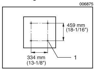
1. Hole diameter 8 mm (5/16")
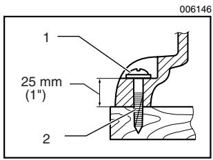
1. 6 mm (1/4") Std. washer
2. No.10 wood screw 40mm (1 - 1 / 2^n) min. length
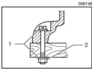
1. 6 mm (1/4") Std. washer
2. 6 mm (1/4") Mounting bolt & Nut tighten securely
Locate the table saw in a well lit and level area where you can maintain good footing and balance. It should be installed in an area that leaves enough room to easily handle the size of your workpieces. The table saw should be secured with four screws or bolts to the work bench or table saw stand using the holes provided in the bottom of the table saw. When securing the table saw on the work bench, make sure that there is an opening in the top of the work bench the same size as the opening in the bottom of the table saw so the sawdust can drop through.
If during operation there is any tendency for the table saw to tip over, slide or move, the work bench or table saw stand should be secured to the floor.
NOTE:
Table saw stand
Models 2702X1 and 2703X1 are standard-equipped with a table saw stand.
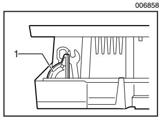
Storing accessories
- Miter gauge
- Rip fence
The miter gauge and wrenches can be stored on the left side of the base and the rip fence can be stored at the rear of the base.
FUNCTIONAL DESCRIPTION
CAUTION:
Always be sure that the tool is switched off and unplugged before adjusting or checking function on the tool.
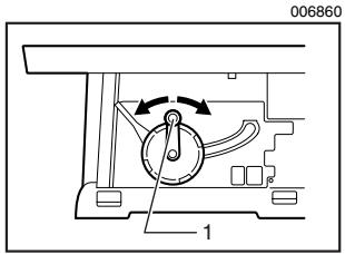
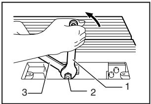
Adjusting the depth of cut
- Handle
The depth of cut may be adjusted by turning the handle. Turn the handle clockwise to raise the blade or counterclockwise to lower it.
NOTE:
- Use a shallow depth setting when cutting thin materials in order to obtain a cleaner cut.
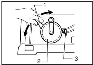
Adjusting the bevel angle
006861
- Lock lever
- Handwheel
- Arrow pointer
Loosen the lock lever counterclockwise and turn the handwheel until the desired angle (0^ - 45^) is obtained. The bevel angle is indicated by the arrow pointer.
After obtaining the desired angle, tighten the lock lever clockwise to secure the adjustment.
CAUTION:
After adjusting the bevel angle, be sure to tighten the lock lever securely.
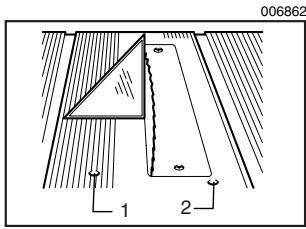
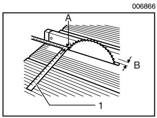
Adjusting positive stops
- 90^ adjusting screw
2.45° adjusting screw
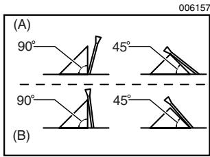
The tool is equipped with positive stops at 90^ and 45^ to the table surface. To check and adjust the positive stops, proceed as follows:
Move the handwheel as far as possible by turning it. Place a triangular rule on the table and check to see if the blade is at 90^ or 45^ to the table surface. If the blade is at an angle shown in Fig. A, turn the adjusting screws clockwise; if it is at an angle shown in Fig. B, turn the
adjusting screws counterclockwise to adjust the positive stops.
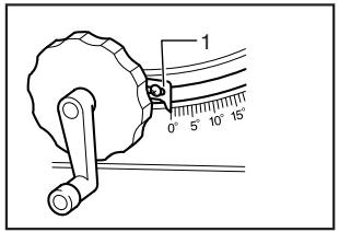
After adjusting the positive stops, set the blade at 90^ to the table surface. Then adjust the arrow pointer so that its right edge is aligned to the 0^ graduation.
006864
1. Arrow pointer
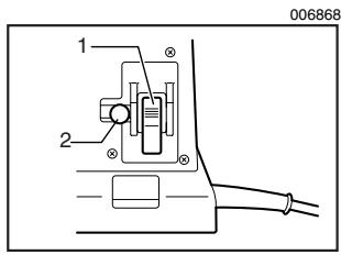
Switch action
- Switch lever
- Key
CAUTION:
- Before plugging in the tool, always check to see that the switch lever actuates properly and returns to the "OFF" position.
This tool is equipped with a special type of switch to prevent unintentional starting. To start the tool, first depress the switch lever. While keeping it depressed, pull its lower portion toward you. To stop the tool, press the lower portion of the switch lever.
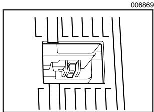
When operating the switch lever, it is convenient to view it through the window area in the table.
CAUTION:
- When not using the tool, remove the key and store it in a secure place. This prevents unauthorized operation.
- Do not pull the switch lever hard without the key. This can cause breakage of the switch.
ASSEMBLY
CAUTION:
Always be sure that the tool is switched off and unplugged before carrying out any work on the tool.
The tool is shipped from the factory with the saw blade and blade guard not in the installed condition. Assemble as follows:
Installing or removing saw blade
CAUTION:
Always be sure that the tool is switched off and unplugged before installing or removing the blade.
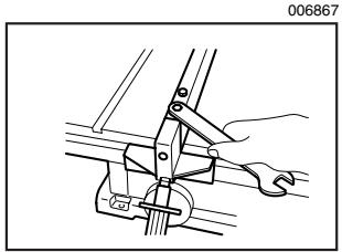
- Use only the Makita socket wrench provided to install or remove the blade. Failure to do so may result in overtightening or insufficient tightening of the hex bolt. This could cause an injury.
006852
- Wrench
- Hex nut
- Offset wrench
Remove the table insert on the table. Hold the outer flange with the offset wrench and loosen the hex nut counterclockwise with the wrench. Then remove the outer flange.
Assemble the inner flange, blade, outer flange and hex nut onto the arbor, making sure that the teeth of the blade are pointing down at the front of the table. Always install the hex nut with its recessed side facing the outer flange.
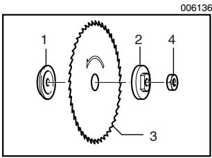
- Inner flange
- Outer flange
- Saw blade
- Hex nut
CAUTION:
- Keep the flange surface clean of dirt or other adhering matter; it could cause blade slippage. Be sure that the blade is installed so that the teeth are aligned in the cutting (turning) direction.
To secure the blade in place, hold the outer flange with the offset wrench, then tighten the hex nut clockwise with the wrench. BE SURE TO TIGHTEN THE HEX NUT SECURELY.

CAUTION:
- Be sure to hold the hex nut carefully with the wrench. If your grip should slip, the wrench may come off the hex nut, and your hand could strike the sharp blade edges.
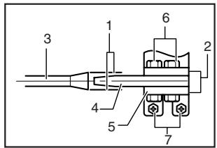
Installing blade guard
- Wrench
- Offset wrench
CAUTION:
Always grasp the striped portion of the offset wrench when tightening the hex bolts. If you tighten the hex bolts while grasping the offset wrench further than the striped portion, the hex bolts may be damaged and/or an injury to your hand may result.
- If the blade and spreader are not aligned properly, a dangerous pinching condition may result during operation. Make sure they are properly aligned. You could suffer serious personal injury while using the tool without a properly aligned spreader.
- NEVER make any adjustments while tool is running. Disconnect the tool before making any adjustments.
There must be a clearance of about 4 - 5mm (5/32" -13/64") between the spreader and the blade teeth.
Adjust the spreader accordingly and tighten the hex bolts (A) securely. Attach the table insert on the table, then check to see that the blade guard works smoothly before cutting.
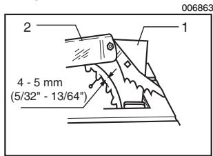
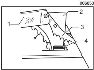
- Spreader
- Blade guard
CAUTION:
Before installing the blade guard, adjust the depth of cut to its maximum elevation. Insert the spreader between the blade guard mounting portion (stay) and the pressure plate.
Tighten the hex bolts (A) with the offset wrench. The spreader installing location is factory-adjusted so that the blade and spreader will be in a straight line. However, if they are not in a straight line, loosen the hex bolts (B) and adjust the blade guard mounting portion (stay) so that the spreader is aligned directly behind the blade. Then tighten the hex bolts (B) to secure the stay.
006856
- These two clearances should be equal
- Blade guard portion
- Blade
- Spreader
- Pressure plate
- Hex bolts (A)
- Hex bolts (B)
Installing and adjusting rip fence
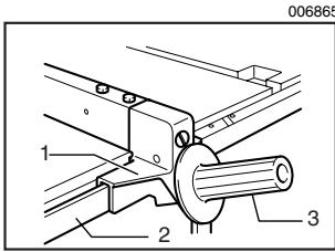
- Fence holder
- Guide rail
- Grip
Raise the grip of the rip fence. Install the rip fence on the table so that the fence holder engages with the guide rail. The rip fence can be secured by lowering the grip.
To check to be sure that the rip fence is parallel with the blade, secure the rip fence 2 - 3 mm (5/64" - 1/8") from the blade. Raise the blade up to maximum elevation. Mark one of the blade teeth with a crayon. Measure the distance (A) and (B) between the rip fence and blade. Take both measurements using the tooth marked with the crayon. These two measurements should be identical. If the rip fence is not parallel with the blade, proceed as follows:
1. Scale
- Hex bolts
- Adjusting nut
-
Grip
-
Turn the adjusting nut counterclockwise a couple of turns.
- Loosen the two hex bolts on the rip fence with the wrench provided.
- Adjust the rip fence until it becomes parallel with the blade.
- Lower the grip to secure the rip fence.
- Tighten the two hex bolts on the rip fence.
CAUTION:
Always grasp the striped portion of the wrench when tightening the hex bolts. If you tighten the hex bolts while grasping the wrench further than the striped portion, the hex bolts may be damaged and/or an injury to your hand may result.
6. With the grip of the rip fence lowered, turn the adjusting nut clockwise to secure the rear end of the rip fence. Do not turn the adjusting nut clockwise excessively. You may have some difficulty adjusting the rip fence parallel with the saw blade when repositioning the rip fence.
CAUTION:
- Be sure to adjust the rip fence so that it is parallel with the blade, or a dangerous kickback condition may occur.
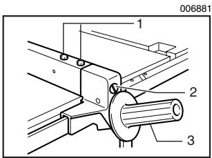
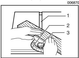
Bring the rip fence up flush against the side of the blade. Make sure that the arrow pointer on the fence holder points to the 0 graduation. If the arrow pointer does not point to the 0 graduation, loosen the screw on the scale plate and adjust the scale plate.
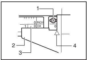
006882
- Screw
- Fence hoder
- Scale plate
- Arrow mark
OPERATION
CAUTION:
Always use "work helpers" such as push sticks and push blocks when there is a danger that your hands or fingers will come close to the blade.
Always hold the workpiece firmly with the table and the rip fence or miter gauge. Do not bend or twist it while feeding. If the workpiece is bent or twisted, dangerous kickbacks may occur.
- NEVER withdraw the workpiece while the blade is running. If you must withdraw the workpiece before completing a cut, first switch the tool off while holding the workpiece firmly. Wait until the blade has come to a complete stop before withdrawing the workpiece. Failure to do so may cause dangerous kickbacks.
- NEVER remove cut-off material while the blade is running.
- NEVER place your hands or fingers in the path of the saw blade. Be especially careful with bevel cuts.
Always secure the rip fence firmly, or dangerous kickbacks may occur.
Always use "work helpers" such as push sticks and push blocks when cutting small or narrow workpieces, or when the dado head is hidden from view while cutting.
Work helpers
Push sticks, push blocks or auxiliary fence are types of "work helpers". Use them to make safe, sure cuts without the need for the operator to contact the blade with any part of the body.
006876
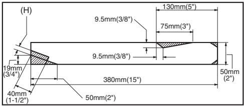
Push stick
A push stick can be easily made from a piece of plywood 19mm (3 / 4^ ) to 25mm(1)^ thick.
Cut out the hatched area on the stick and smooth edges with a file. (H) dimension should be less than 12.7mm (1/ 2^n ) so as to be thinner than the workpiece.
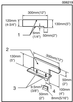
Push block
- Face/edge parallel
- Handle
- Wood screw
- Glue together
Use a 19mm (3 / 4^ ) piece of plywood.
Handle should be in center of plywood piece. Fasten with glue and wood screws as shown. Small piece 9.5mm× 8 mm × 50mm (3 / 8^ × 5 / 16^ × 2^ ) of wood must always be glued to plywood to keep the blade from dulling if the operator cuts into push block by mistake. (Never use nails in push block.)
Auxiliary fence
006883
- Face/edge parallel
Make auxiliary fence from 9.5mm (3/8") and 19mm (3/ 4") plywood pieces.
Fasten with glue and wood screws.
Wood facing (rip fence)
- No.10 wood screws (long enough to penetrate halfway into facing)
A wood facing should be used for operations when the blade comes close to the rip fence. Wood facing for the rip fence should be the same size as the rip fence. Make sure the bottom of facing is flush with the table surface.
Ripping
CAUTION:
- When ripping, remove the miter gauge from the table.
- When cutting long or large workpieces, always provide adequate support behind the table. DO NOT allow a long board to move or shift on the table. This will cause the blade to bind and increase the possibility of kickback and personal injury. The support should be at the same height as the table.
Before operating the table saw, check to be sure that the antikickback paws operate properly. Turn the tool off and unplug it. Feed the workpiece under the blade guard and along both sides of the blade to simulate cutting. Try to withdraw the workpiece on each side by pulling it toward you. The antikickback paws should grab the workpiece and prevent it from moving back toward the operator. Always keep the antikickback paws sharp so they will operate properly. Keep them sharp by using a round-shaped file to maintain the original shape of the paws.
- Adjust the depth of cut a bit higher than the thickness of the workpiece.
- Position the rip fence to the desired width of rip and lock in place by lowering the grip. Before ripping, make sure the rear end of the rip fence is secured firmly. If it is not secured enough, follow the proce
dures in the section titled "Installing and adjusting rip fence".
- Turn the tool on and gently feed the workpiece into the blade along with the rip fence.
(1) When the width of rip is 150mm (6") and wider, carefully use your right hand to feed the workpiece. Use your left hand to hold the workpiece in position against the rip fence.
(2) When the width of rip is 65mm - 150mm (2- 1 / 2'' - 6'' ) wide, use the push stick to feed the workpiece.

- Push stick
(3) When the width of rip is narrower than 65mm (2-1/2"), the push stick cannot be used because the push stick will strike the blade guard. Use the auxiliary fence and push block. Attach the auxiliary fence to the rip fence with two "C" clamps.
- Auxiliary fence
Feed the workpiece by hand until the end is about 25mm (1") from the front edge of the table. Continue to feed using the push block on the top of the auxiliary fence until the cut is complete.

1. Push block
2. Auxiliary fence
Cross cutting
CAUTION:
- When making a crosscut, remove the rip fence from the table.
- When cutting long or large workpieces, always provide adequate support to the sides of the table. The support should be at the same height as the table.
Always keep hands away from path of blade.
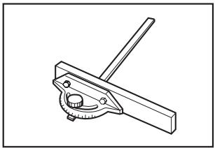
Miter gauge

1. Cross cutting
2. Mitering
3. Bevel cutting
4. Compound mitering (angles)
Use the miter gauge for the 4 types of cutting shown in the figure.
CAUTION:
- Secure the knob on the miter gauge carefully.
- Avoid creep of workpiece and gauge by firm workholding arrangement, especially when cutting at an angle.
- NEVER hold or grasp the intended "cut-off" portion of the workpiece.
Use of miter gauge
1. Groove
2. Miter gauge
3. Knob
Slide the miter gauge into the thick grooves in the table.
Loosen the knob on the gauge and align to desired angle
(0^ to 60^) . Bring stock flush up against fence and feed gently forward into the blade.
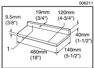
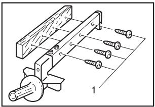
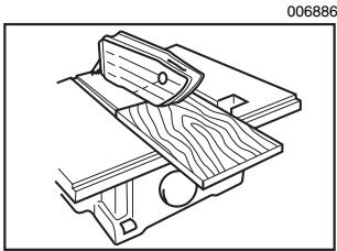
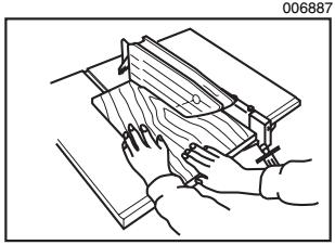
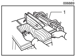
Auxiliary wood facing (miter gauge)
006885
To prevent a long board from wobbling, fit the miter gauge with an auxiliary fence board. Fasten with bolts/nuts after drilling holes, but fasteners must not protrude from the face board.
MAINTENANCE
CAUTION:
Always be sure that the tool is switched off and unplugged before attempting to perform inspection or maintenance.
Cleaning
Clean out sawdust and chips from time to time. Carefully clean the blade guard and moving parts inside the table saw.
Lubrication
To keep the table saw in tip-top running condition, and to assure maximum service life, oil or grease the moving parts and rotating parts from time to time.
Lubrication places:
- Threaded shaft to elevate the blade
Hinge to rotate the frame
Elevation guide shafts on motor
Gear to elevate the blade
Replacing carbon brushes
001145
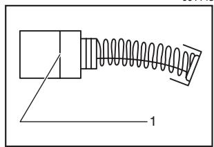
1. Limit mark
Remove and check the carbon brushes regularly. Replace when they wear down to the limit mark. Keep the carbon brushes clean and free to slip in the holders.
Both carbon brushes should be replaced at the same time. Use only identical carbon brushes.
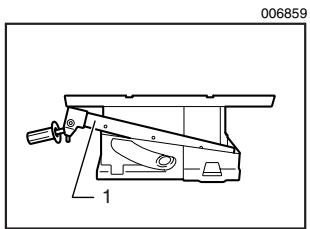
Use a holder cap opener to remove the brush holder caps. To replace the carbon brush in the side near the table, lower the blade as far as possible by turning the handle. Loosen the lock lever, tilt the blade and secure it at 45^ . Then loosen the brush holder cap while viewing it through the opening of the base. Remove the worn carbon brushes, insert the new ones and secure the brush holder caps.
After replacing brushes, plug in the tool and break in brushes by running tool with no load for about 10 minutes. Then check the tool while running and electric brake operation when releasing the switch trigger. If electric brake is not working well, ask your local Makita service center for repair.
- Holder cap opener
- Brush holder cap
To maintain product SAFETY and RELIABILITY, repairs, any other maintenance or adjustment should be performed by Makita Authorized or Factory Service Centers, always using Makita replacement parts.
ACCESSORIES
CAUTION:
These accessories or attachments are recommended for use with your Makita tool specified in this manual. The use of any other accessories or attachments might present a risk of injury to persons. Only use accessory or attachment for its stated purpose.
If you need any assistance for more details regarding these accessories, ask your local Makita Service Center.
Dado head set (Part No. 191543-4)
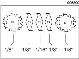
A dado is cutting a rabbit or a wide groove into the workpiece. The dado head set consists of two outside cutters, three inside cutters and paper washers.
- Outside cutters: 6" diameter, 1/8" thick, 5/8"arbor hole, 2 pcs.
- Inside cutters: 6" diameter, 1/8" thick, 5/8" arbor hole, 2 pcs.
- Inside cutter: 6" diameter, 1/16" thick, 5/8" arbor hole, 1 pc.
- Paper washers: 5/8"arbor hole, 6 pcs.
Various combinations of these cutters are used to cut grooves from 1/8 to 1/2 for use in making joints, tenoning, grooving, etc.
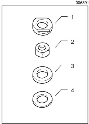
Dado flange set (Part No. 192693-8)
- Dado outer flange
When cutting groove 1 / 4" , 5 / 16" , 3 / 8" , 7 / 16" or 1 / 2" , use this dado outer flange.
- Dado hex nut
When cutting groove 1 / 4" 5 / 16" 3 / 8" 7 / 16" or 1 / 2" use this dado hex nut.
- Ring
When cutting groove 1 / 4" , 5 / 16" , 3 / 8" , 7 / 16" or 1 / 2" , use this ring.
- Washer
When cutting groove 1/4" , 5/16" or 3/8" , use this washer.
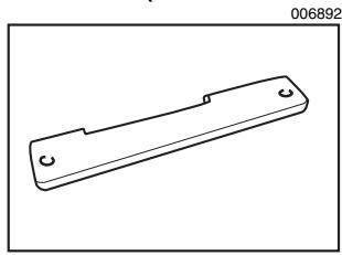
Table insert (Part No. 317061-6)
When cutting grooves 5 / 16" 3 / 8",7 / 16" or 1 / 2" use this table insert instead of the standard table insert.
To install the dato head set, proceed as follows:
- Turn the tool off and unplug it before installing.
- Remove the blade guard with the spreader.
- Install the dato head set with the teeth pointing down at the front of the table.
- Use the chart below to select the proper cutters to obtain the various cutting widths.
006893
| CUTWIDTH | Spindle | Innerflange | Ring | OutsideCutter | 1/8"Insidecutter | 1/16"Insidecutter | Outsidecutter | Outerflange | Washer | DadoOuterflange | Hexnut | DadoHexnut |
| 1/8" | ● | ● | ● | ● | ● | |||||||
| 1/4" | ● | ● | ● | ● | ● | ● | ● | |||||
| 5/16" | ● | ● | ● | ● | ● | ● | ● | ● | ||||
| 3/8" | ● | ● | ● | ● | ● | ● | ● | ● | ||||
| 7/16" | ● | ● | ● | ● | ● | ● | ● | ● | ||||
| 1/2" | ● | ● | ● | ● x2 | ● | ● | ● |
CAUTION:
- For a 1/8 cut width, the outside cutter is assembled to the spindle in the same manner as the saw blade.
- The outer flange or the dado outer flange must be used for each cut width.
The hex nut alone must not be used to secure the dado on to the spindle.
NOTE:
- When widths slightly greater than the above are required, fit the paper washers in between the inside and outside cutters to adjust the width.
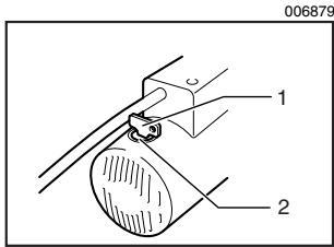
- Arrange the cutters so that the tips of the inside cutters are positioned at the gullets of the outside cutter. When more than one inside cutter is used, space the tips of the inside cutters equidistantly in relation to one another. Poorly spaced cutters may cause vibration and noise.
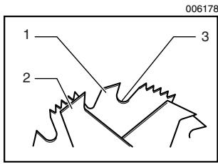
- Outside cutter
- Inside cutter
- Gullet
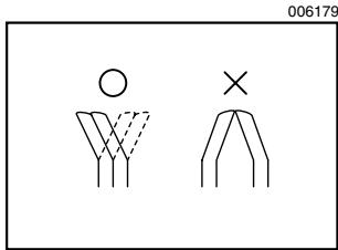
When installing two outside cutters without any inside cutter, be sure that the cutter tips do not face each other.
- While tightening the hex nut, be careful to maintain the even spacing between the tips of the inside cutters.
- Rotate the dado head one turn by hand to make sure that it does not contact anything before operation.
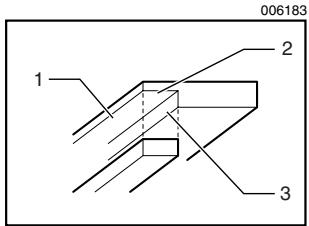
When dadoing, use featherboards. The diagram shown illustrates dimensions for making a typical featherboard. It should be made from a straight piece of wood that is free of knots or cracks.
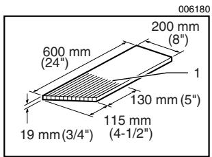
1. Kerf should be about 6 mm (1/4") apart
Featherboards are used to keep the workpiece in contact with the rip fence and table as shown, and to stop kickbacks.
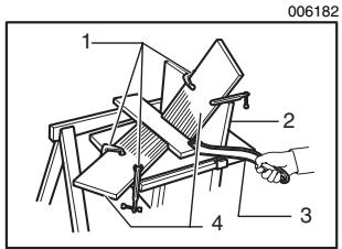
- C clamps
- Facing board
- Push stick
- Featherboard
To install featherboards, proceed as follows:
- Turn the tool off and unplug it.
- Add 8" high flat facing board to the rip fence, the full length of the rip fence.
- Mount featherboards to the rip fence and table as shown, so that the leading edges of the featherboards will support the workpiece until the cut is completed, and the workpiece has been pushed completely past the cutter with a push stick.
- Make sure featherboards are securely attached.
CAUTION:
Only the Makita dado head set (Part No. 191543-4) should be used with Makita table saw Model 2702/Model 2703.Do not use dado combinations wider than 13mm(1 / 2^ )
- After dadoing, ALWAYS replace the blade guard with the spreader back in its original position on the table saw.
NEVER attempt bevel cuts when dadoing.
- NEVER dato if there is vibration (flutter) or a strange noise.
NEVER attempt dados in other than wood.
- Do not use the dado set for cut-offs.
- Feed work slowly, especially when cutting deep or wide grooves or dados. If a deep cut is needed, make several passes through the workpiece rather than one deep, wide cut. Fast or abrupt feeds can be dangerous.
- Use a push stick. When the dado head is hidden from view while cutting, your hands should never be on top of the stock.
- A very dangerous throwback can result if the wood becomes stuck and you try to remove it by pulling toward you. Always stop the tool and wait for dad to head to come to a complete stop. Then simply withdraw the wood.
WARNING:
- Use extra caution when the guard assembly is removed for any non-through sawing operation such as dadoing, rabbeting or re-sawing. Replace guard immediately after non-through sawing is completed.
How to perform rabbeting
- Rabbit
- Second cut
-
First cut
-
Remove blade guard.
- Attach auxiliary fence to rip fence for cuts that run the length of the stock. Facing should be as high as the workpiece is wide. Adjust fence and blade to desired dimensions.
- First cut: Hold board flat on table as in ordinary rip- ping.
- Second cut: Set workpiece on its edge. (Use featherboards, push stick, push block and so on, using precautions, safety rules and guidelines for ripping or related work.)
- For end-type rabbeting, if the workpiece is less than 10 - 1 / 2'' wide, rest the wood flat on the table against the miter gauge (with wood facing). The rip fence should not be used.
- After rabbeting is completed, immediately re-install the blade guard as before.
Table saw stand
NOTE:
- The following is description only for the tools equipped with a table saw stand. For table saw stands as optional accessories, refer to the instruction manuals for table saw stands provided with them.
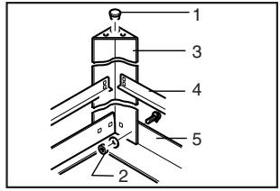
Place the stays on a level location and assemble the legs inside. Secure with the bolts and nuts, then attach the rubber caps to the ends of the legs.
006877
- Rubber cap
- Nut
- Leg
- Under stay
- stay
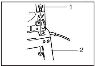
Now set the table saw on top of the assembled stand and secure with four bolts, washers and nuts.
006878
- Bolt
- Stand
NOTE:
- Models 2702X1 and 2703X1 are standard-equipped with a table saw stand.
- Steel & Carbide-tipped saw blades
006586
| Table/Miter saw blades | For general purpose cuts for table and miter saws. |
| Combination | General purpose blade for fast and smooth rip, crosscuts and miters. |
| Fine cross cuts | For sand-free cuts cleanly against the grain. |
- Sub table set (Left / Right)
Rip fence
Miter gauge
Offset wrench 13-22
Wrench 19
Key (Switch button)
Holder cap opener
Joint ( for connecting to dust collector ) - Stand set
EN0006-1
MAKITA LIMITED ONE YEAR WARRANTY
Warranty Policy
Every Makita tool is thoroughly inspected and tested before leaving the factory. It is warranted to be free of defects from workmanship and materials for the period of ONE YEAR from the date of original purchase. Should any trouble develop during this one year period, return the COMPLETE tool, freight prepaid, to one of Makita's Factory or Authorized Service Centers. If inspection shows the trouble is caused by defective workmanship or material, Makita will repair (or at our option, replace) without charge.
This Warranty does not apply where:
- repairs have been made or attempted by others:
- repairs are required because of normal wear and tear:
- the tool has been abused, misused or improperly maintained:
alterations have been made to the tool.
IN NO EVENT SHALL MAKITA BE LIABLE FOR ANY INDIRECT, INCIDENTAL OR CONSEQUENTIAL DAMAGES FROM THE SALE OR USE OF THE PRODUCT. THIS DISCLAIMER APPLIES BOTH DURING AND AFTER THE TERM OF THIS WARRANTY.
MAKITA DISCLAIMS LIABILITY FOR ANY IMPLIED WARRANTY, INCLUDING IMPLIED WARRANTY OF "MERCHANTABILITY" AND "FITNESS FOR A SPECIFIC PURPOSE," AFTER THE ONE YEAR TERM OF THIS WARRANTY.
This Warranty gives you specific legal rights, and you may also have other rights which vary from state to state. Some states do not allow the exclusion or limitation of incidental or consequential damages, so the above limitation or exclusion may not apply to you. Some states do not allow limitation on how long an implied warranty lasts, so the above limitation may not apply to you.
FRANÇAIS
SPÉCIFICATIONS
| Modèle | 2702 / 2702X1 | 2703 / 2703X1 | |
| Alésage central | 5/8" | ||
| Diamètre de la lame | 210 mm (8-1/4") | 255 mm (10") | |
| Capacités de coupe max. | 90° | 68 mm (2-11/16") | 91 mm (3-9/16") |
| 45° | 47 mm (1-3/4") | 63 mm (2-1/2") | |
| Capacités de lambrissage maximales | 13 mm (1/2") | ||
| Vitesse à vide (T/MIN) | 4,600/min. | ||
| Taille de la table (P × L) | 686 mm x 560 mm (27" x 22") | ||
| Dimensions (L x I x H) | 560 mm x 686 mm x 458 mm (22" x 27" x 18") | ||
| Poids net | 18 kg (40 lbs) | ||
| LARGEUR DE COUPE | Arbre | Flasque intérieur | Bague | Couteau extérieur | Couteau intérieur 1/8 po | Couteau intérieur 1/16 po | Couteau extérieur | Flasque extérieur | Rondelle | Flasque Dado extérieur | Écrou hexa- gonal | Écrou hexa- gonal Dado |
| 1/8" | ● | ● | ● | ● | ● | |||||||
| 1/4" | ● | ● | ● | ● | ● | ● | ● | |||||
| 5/16" | ● | ● | ● | ● | ● | ● | ● | ● | ||||
| 3/8" | ● | ● | ● | ● | ● | ● | ● | ● | ||||
| 7/16" | ● | ● | ● | ● | ● | ● | ● | ● | ||||
| 1/2" | ● | ● | ● | ● x2 | ● | ● | ● |
ATTENTION:
Some dust created by power sanding, sawing, grinding, drilling, and other construction activities contains chemicals known to the State of California to cause cancer, birth defects or other reproductive harm. Some examples of these chemicals are:
- lead from lead-based paints,
crystalline silica from bricks and cement and other masonry products, and - arsenic and chromium from chemically-treated lumber.
Your risk from these exposures varies, depending on how often you do this type of work. To reduce your exposure to these chemicals: work in a well ventilated area, and work with approved safety equipment, such as those dust masks that are specially designed to filter out microscopic particles.
< USA solamente >