
FA-EBA1 - USB Drive SONY - Free user manual and instructions
Find the device manual for free FA-EBA1 SONY in PDF.


| Product type | External battery adapter for flash |
| Brand | Sony |
| Model | FA-EBA1 |
| Compatibility | Sony flash with DC IN jack (e.g., HVL-F56AM, HVL-F60RM) |
| Power supply | 4 or 8 AA batteries (alkaline or rechargeable Ni-MH) |
| Rated voltage | 6 V - 2.6 W |
| Dimensions (W x H x D) | 77 x 174 x 23 mm |
| Weight (without batteries) | 249 g |
| Operating temperature | 0 °C to 40 °C |
| Storage temperature | -20 °C to +60 °C |
| Number of flashes (alkaline batteries) | Approx. 450 or more (with HVL-F60RM) |
| Number of flashes (Ni-MH batteries) | Approx. 660 or more (with HVL-F60RM) |
| Flash frequency (alkaline) | Approx. 0.1 to 0.8 seconds |
| Flash frequency (Ni-MH) | Approx. 0.1 to 0.6 seconds |
| Protection | Protection against water and dust ingress |
| Material | Not specified (estimated: robust plastic) |
| Color | Black |
| Package contents | Adapter, battery magazine, case, set of printed documents |
| Maintenance | Clean with a soft, dry cloth; remove sand with a blower |
| Safety | Do not expose to rain, do not disassemble, avoid metallic objects |
Frequently Asked Questions - FA-EBA1 SONY
User questions about FA-EBA1 SONY
0 question about this device. Answer the ones you know or ask your own.
Ask a new question about this device
Download the instructions for your USB Drive in PDF format for free! Find your manual FA-EBA1 - SONY and take your electronic device back in hand. On this page are published all the documents necessary for the use of your device. FA-EBA1 by SONY.
USER MANUAL FA-EBA1 SONY
External Battery Adaptor for Flash
AR تعليمات التشفيل
© 2017 Sony Corporation
Printed in China

4736454130
FA-EBA1
SONY®
External Battery Adaptor for Flash
Operating Instructions GB
Mode d'emploi FR
To reduce fire or shock hazard, do not expose the unit to rain or moisture.
Before use
Notes on this unit
This External Battery Adaptor is made especially for the flash with a DC IN terminal.
- Before use, make sure that your flash is compatible with this unit.
• See the operating instructions, and refer to the operating instructions of your flash.
Notes on handling this unit
This unit is designed with ingress protection in mind, but not with the intention to completely protect against dust and water ingress. Do not use the unit in the rainy weather.
Safety
To avoid hazards, such as a fire or an electrical shock, observe the following.
- Do not carry around or store this unit along with metal objects, such as coins and hairpins.
- Do not attempt to disassemble this unit, or make an alteration or a short circuit on this unit.
Unpacking
If you find anything missing, please contact your dealer.
The number in the parentheses indicates the quantity.
- External Battery Adaptor for Flash (1)
- Battery magazine (1)
- Case (1)
- Set of printed documentation
Locating parts and controls
GB
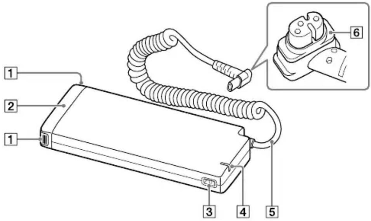
1 Battery magazine unlock buttons
② Battery magazine
③ Strap hole
4 Charge lamp
5 Connecting cord
6 Moisture-resistant packing
Before you connect this unit to the flash product, HVL-F56AM, remove the Moisture-resistant packing.
Preparations
Inserting batteries
This unit can accommodate either set of the following:
- Four AA-size alkaline batteries (4 or 8)
- Four AA-size rechargeable nickel-metal hydride (Ni-MH) batteries (4 or 8)
No batteries are supplied with the unit.
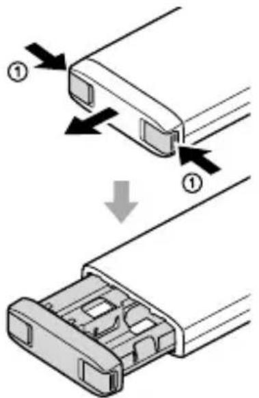
1 Press and hold the battery magazine unlock buttons in the direction of the arrows (①), and then pull out the battery magazine.
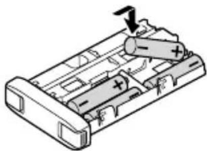
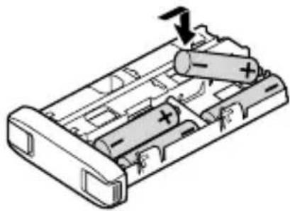
2 Insert the batteries into the battery chamber as illustrated (☐+) by putting the positive battery terminal
first. (indicates the direction of the batteries.)
natural_image
Diagram of a battery pack with two cylindrical components and an arrow indicating direction (no text or symbols)- When inserting each of the batteries, be sure to put its positive terminal first into the battery chamber.
- When removing each of the batteries, push it up from the back of the battery chamber.
- Insert 4 batteries into the battery chamber on the top side of the battery magazine and 4 batteries into the one on the bottom side.
This unit is capable of operating with 4 batteries inserted in the battery chamber either on the top side or on the bottom side of the battery magazine.
3 Put the battery magazine back into this unit and push in the magazine until it clicks into place.
Using this unit with the flash
GB
This External Battery Adaptor is made especially for the flash with a DC IN terminal.
Before use, make sure that your flash is compatible with this unit.
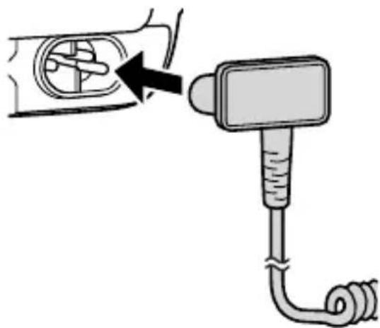
1 Turn off the power to the flash and remove the terminal cap.
2 Grasp the plug of the connecting cord and plug the cord to the DC IN terminal on the flash.
natural_image
Diagram showing a car interior with a valve and a handheld device connected to a coiled cable (no text or symbols)- For the flash product models compatible with this unit, visit the Sony website in your area.
3 Turn on the power to the flash.
- Keep the batteries in the battery chamber of the flash. (The flash needs its own batteries for operation.)
4 When the TEST button on the back of the flash lights in orange to indicate that the flash is ready to fire, take a photo.
- The charge lamp on this unit lights while the flash is charging up itself. - If the flash fires in quick succession for a short period of time, its built-in safety unit will be triggered to suspend flash firing and the flash stops charging up itself (overheat). On this unit, the charge lamp will blink.
In such a case, be sure to remove this unit from the flash and leave this unit unused for about 10 minutes to let it cool down.
- For details of the using of flash, refer to the operating instructions supplied with your flash.
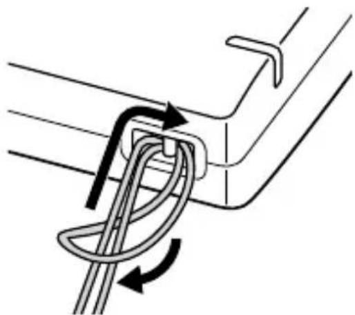
You can attach a strap to the strap hole on this unit.
natural_image
Diagram of a rope knot being twisted between two metal rods (no text or symbols)When to replace batteries
Specify 1/1 for the flash power level and fire a test-flash to measure the time period before the TEST button on the back of the flash lights in orange to indicate that the flash is ready to fire. When the flash charge-up time exceeds the following time period, replace the batteries both in the flash and in this unit.
With AA alkaline batteries: 30 seconds
With AA nickel metal hydride batteries: 10 seconds
Note
- When the flash is running out of power, the low-battery indicator may be displayed on the LCD panel of the flash despite the flash charge-up time being shorter than the above time period. In such a case, replace the batteries.
Notes on use
GB
While photographing
- Do not use the flash 20 times in a row or in quick succession in order to prevent heating and degradation of the unit and batteries. (when the flash power level is 1/32, 40 times in a row.) Stop using the unit and cool it for 10 minutes or more, if the flash is triggered up to the limit for the number of times in quick succession.
- Do not carry this unit with the flash attached. It may result in a malfunction.
- When replacing the battery magazine, be sure to keep your fingertip(s) from being caught between the magazine and this unit to avoid possible injuries.
Batteries
- The battery level displayed on the LCD panel of the flash may be lower than the actual battery capacity, due to temperature and storage conditions. The displayed battery level may be restored to the correct value after the flash has been used a few times.
-
Nickel-metal hydride batteries can lose power suddenly. If the low-battery indicator of the flash starts blinking or the flash can no longer be used while taking pictures, change or recharge the batteries.
-
Do not use lithium-ion batteries in this unit as they may prevent the unit from delivering full performance.
- The flash frequency and number of flashes provided by new batteries may vary from the values shown in the table, depending on the time elapsed since manufacture of the batteries.
- When you replace the batteries of this unit that has been in use, disconnect the unit from the flash and wait for a few minutes before you remove the batteries. The batteries may be hot, depending on the battery type. Remove them carefully.
- Remove and store the batteries when you do not intend to use this unit for a long time.
Temperature
- The unit may be used over a temperature range of 0^ to 40^ .
- To prevent condensation forming on the unit, place it in a sealed plastic bag when bringing it from a cold environment into a warm environment. Allow it to reach room temperature before removing it from the bag.
- Battery capacity decreases at colder temperatures. Keep this unit and spare batteries in a warm inside pocket when shooting in cold weather. The low-battery indicator may blink even when there is some power left in the batteries in cold weather. Batteries will regain some of their capacity when warmed to normal operating temperature.
Do not use/store the product in the following places
- In an extremely hot, cold or humid place
In places such as in a car parked in the sun, this unit may become deformed and this may cause a malfunction. - Storing under direct sunlight or near a heater
This unit may become discolored or deformed, and this may cause a malfunction.
• In a location subject to rocking vibration
• Near strong magnetic place
• In sandy or dusty places Be careful not to let sand or dust get into the product.
This may cause the product to malfunction, and in some cases this malfunction cannot be repaired.
Maintenance
Clean the unit with a dry soft cloth. If the unit has been in contact with sand, wiping will damage the surface, and it should therefore be cleaned gently using a blower. In the event of stubborn stains, use a cloth lightly moistened with water or tepid water, and then wipe the unit clean with a dry soft cloth. Never use strong solvents, such as thinner or benzine, as these damage the surface finish.
Specifications
GB
Flash frequency/count
When used in combination with HVL-F60RM
| With alkaline batteries | With nickel-metal hydride batteries | |
| Flash frequency (sec) | Approx. 0.1 - 0.8 Approx. | 0.1 - 0.6 |
| Flash count (times) | Approx. 450 or more Approx. | 0.660 or more |
- The flash count indicates the approximate number of flashes available before new batteries wear out.
Other specifications
Power rating: 6 V, 2.0 W
Operating temperature: 0 °C to 40 °C (32 °F to 104 °F)
Storage temperature: -20 °C to +60 °C (-4 °F to +140 °F)
Dimension (w/h/d) (Approx.): 77 x 174 x 23 mm (3 1/8 x 6 7/8 x 29/32 in.)
Mass (Approx.): 249 g (8.8 oz) (including the weight of the battery magazine with no batteries)
Functions in these operating instructions depend on testing conditions at our firm.
Design and specifications are subject to change without notice.
AVERTISSEMENT
natural_image
Diagram of a battery pack with two batteries and an arrow indicating direction (no text or symbols)natural_image
Diagram showing a car door handle being inserted into a plug, with no text or symbols present.natural_image
Diagram of a rope knot being twisted between two metal rods (no text or symbols)natural_image
Diagram of a battery pack with internal components and an arrow indicating direction (no text or symbols)natural_image
Diagram showing a mechanical device connected to a motor or connector, with no visible text or symbols.natural_image
Diagram of a rope knot being twisted between two vertical bars (no text or symbols)natural_image
Diagram of a battery pack with two cylindrical components and an arrow indicating direction (no text or symbols)natural_image
Diagram showing a mechanical device with a pipe and cable inserted, no text or symbols presentnatural_image
Diagram of a rope knot being twisted between two metal rods (no text or symbols)natural_image
Diagram of a battery pack with two cylindrical cells and an arrow indicating direction (no text or symbols)natural_image
Diagram showing a car interior with a valve and a handheld device connected to a coiled cable (no text or symbols)natural_image
Diagram of a rope knot being twisted between two metal rods (no text or symbols)natural_image
Diagram of a battery pack with two cylindrical components and an arrow indicating direction (no text or symbols)natural_image
Diagram showing a mechanical device with a pipe and cable inserted into a housing (no text or symbols)natural_image
Diagram of a rope knot being twisted between two metal rods (no text or symbols)natural_image
Diagram of a battery pack with internal components and an arrow indicating direction (no text or symbols)natural_image
Diagram showing a car interior being connected to a handheld device via tubing (no text or symbols)natural_image
Diagram of a rope knot being twisted between two metal links (no text or symbols)natural_image
Diagram of a battery pack with two batteries and an arrow indicating direction (no text or symbols)natural_image
Diagram showing a car interior with a valve and a handheld device connected to a coiled cable (no text or symbols)natural_image
Diagram of a rope knot being twisted between two metal rods (no text or symbols)natural_image
Diagram of a battery pack with two batteries and an arrow indicating direction (no text or symbols)natural_image
Diagram showing a mechanical device with a pipe fitting and a circular component inserted into it, no text or symbols present.natural_image
Diagram of a rope knot being twisted between two metal rods (no text or symbols)natural_image
Diagram of a battery pack with two cylindrical components and an arrow indicating direction (no text or symbols)natural_image
Diagram showing a device being inserted into a circular component, with a magnified view of the device's cable (no text or symbols present)natural_image
Diagram of a rope knot being twisted between two metal beams (no text or symbols)2 Podl'a obrázka (☐) vložte batérie do priehradky na batérie, pričom najprv vkladajte kladnú koncovku
batérie. ( ☐značuje smer batérií.)
natural_image
Diagram of a battery pack with two batteries and an arrow indicating direction (no text or symbols)- Pri vkladaní každej z batérií je potrebné do priehradky na batérie najprv vložit kladnú koncovku batérie.
- Pri vyberaní každú z batérií vytlačte smerom nahor zo zadnej strany priehradky na batérie.
• 4 batérie vložte do priehradky na batérie v hornej časti zásobníka na batérie a 4 batérie vložte do priehradky na batérie v spodnej časti. Táto jednotka dokáže fungovať s napájaním zo 4 batérií v priehradke na batérie v hornej alebo v spodnej časti zásobníka na batérie.
natural_image
Diagram showing a mechanical device connected to a motor or connector, with no visible text or symbols.natural_image
Diagram of a rope knot being twisted between two metal rods (no text or symbols)natural_image
Diagram of a battery pack with two batteries and one moving inside (no text or symbols)natural_image
Diagram showing a mechanical device connected to a motor or connector, with no visible text or symbols.natural_image
Diagram of a rope knot being twisted between two metal rods (no text or symbols)natural_image
Diagram of a battery pack with two batteries and an arrow indicating direction (no text or symbols)natural_image
Diagram showing a device being inserted into a car's vent, with no text or symbols present.natural_image
Diagram of a rope knot being twisted between two vertical bars, showing rotational motion (no text or symbols)natural_image
Diagram of a battery pack with two batteries and an arrow indicating direction (no text or symbols)natural_image
Diagram showing a device being inserted into a socket, with no visible text or symbolsnatural_image
Diagram of a rope knot being twisted between two metal rods (no text or symbols)natural_image
Diagram of a battery pack with two cylindrical components and an arrow indicating direction (no text or symbols)natural_image
Diagram showing a device being inserted into a car's vent, with no text or symbols present.natural_image
Diagram of a rope knot being twisted between two metal links (no text or symbols)natural_image
Diagram of a battery pack with two cylindrical components and an arrow indicating direction (no text or symbols)natural_image
Diagram showing a device being inserted into a car's vent, with no text or symbols present.natural_image
Diagram of a rope knot being twisted between two metal links (no text or symbols)natural_image
Diagram of a battery pack with internal components and a downward arrow indicating action (no text or symbols)natural_image
Diagram showing a mechanical device with a pipe and cable inserted into a circular component (no text or symbols)natural_image
Diagram of a rope knot being twisted between two vertical bars (no text or symbols)natural_image
Diagram of a battery pack with two cylindrical components and an arrow indicating direction (no text or symbols)natural_image
Diagram showing a mechanical device with a pipe and cable inserted, no text or symbols presentnatural_image
Diagram of a rope knot being twisted between two vertical bars (no text or symbols)natural_image
Diagram of a battery pack with two batteries and an arrow indicating direction (no text or symbols)natural_image
Diagram showing a car engine component being inserted into a plug, with no text or symbols present.natural_image
Diagram of a rope knot being twisted between two metal rods (no text or symbols)CT
電池更換時機
제품명칭: External Battery Adaptor for Flash
모델명: FA-EBA1
제조연월:사용 설명서에 표시
제조자: Sony Corporation, Made in Myanmar
사용하기 전에
본 기기에 대한 주의사항
natural_image
Diagram of a battery pack with internal components and an arrow indicating direction (no text or symbols)natural_image
Diagram showing a mechanical device with a pipe fitting and a circular component inserted into a housing (no text or symbols)natural_image
Diagram of a rope knot being twisted between two metal rods (no text or symbols)배터리 교체시기
natural_image
Diagram of a rope knot being twisted between two metal rods (no text or symbols)natural_image
Diagram of a battery pack with an arrow indicating direction, showing internal components and polarity signs (no text or symbols)

- External Battery Adaptor for Flash
- SONY®
- Before use
- Notes on this unit
- Notes on handling this unit
- Safety
- Unpacking
- Locating parts and controls
- Preparations
- Inserting batteries
- Using this unit with the flash
- When to replace batteries
- Note
- Notes on use
- While photographing
- Batteries
- Temperature
- Do not use/store the product in the following places
- Maintenance
- Specifications
- Flash frequency/count
- Other specifications
- AVERTISSEMENT
- 電池更換時機
- 사용하기 전에
- 본 기기에 대한 주의사항
- 배터리 교체시기
Brand : SONY
Model : FA-EBA1
Category : USB Drive