
Reactor 40 Kicker - Uncategorized GARMIN - Free user manual and instructions
Find the device manual for free Reactor 40 Kicker GARMIN in PDF.


| Product type | Marine autopilot adapter kit |
| Brand | Garmin |
| Model | Reactor 40 Kicker |
| Compatibility | Yamaha® EFI engines (auxiliary outboards) |
| Included components | Steering actuator, throttle actuator, motor bracket, tiller arm, mounting hardware |
| Main functions | Autopilot control of auxiliary engine (steering and throttle) |
| Power supply | Via the autopilot system (12 V DC) |
| Material | Steel, nylon, aluminum |
| Installation | Requires professional installation; follow provided instructions |
| Idle adjustment | Manual setup after throttle cable installation |
| Maintenance | Check fastener tightness; apply LOCTITE 435 threadlocker |
| Safety | Read safety instructions before installation |
| Dimensions (steering actuator) | Approximately 150 mm length (to be confirmed) |
| Weight | Approximately 1 kg (estimate) |
| Operating temperature | -15 to 70 °C (depending on components) |
| Provided documents | Installation manual (40 pages) |
| Warranty | Standard Garmin manufacturer warranty |
| User rating | 8.5/10 |
| Repairability | Spare parts available through Garmin and authorized dealers |
| Product code | Reactor 40 Kicker |
Frequently Asked Questions - Reactor 40 Kicker GARMIN
User questions about Reactor 40 Kicker GARMIN
0 question about this device. Answer the ones you know or ask your own.
Ask a new question about this device
Download the instructions for your Uncategorized in PDF format for free! Find your manual Reactor 40 Kicker - GARMIN and take your electronic device back in hand. On this page are published all the documents necessary for the use of your device. Reactor 40 Kicker by GARMIN.
USER MANUAL Reactor 40 Kicker GARMIN
Installation Instructions 2
Garmin ^® and the Garmin logo are trademarks of Garmin Ltd. or its subsidiaries, registered in the USA and other countries. Reactor ^™ is a trademark of Garmin Ltd. or its subsidiaries. This trademark may not be used without the express permission of Garmin.
Yamaha ^c is a trademark of the Yamaha Motor Corporation. LOCTITE ^e is a trademark of Henkel Corporation in the U.S. and elsewhere.
Reactor™ 40 Kicker Yamaha® EFI Adapter Installation Instructions
Getting Started
CAUTION
You must refer to the important safety information in the Garmin ^® Reactor ^™ 40 Kicker Installation Instructions before installing and using this product.
To use a Garmin Reactor 40 Kicker autopilot system with select Yamaha® motors, you must also install components provided in this kit. For proper installation, you must use these instructions along with the instructions provided in the autopilot corepack.
NOTE: For the best results, the autopilot system should be installed by a knowledgeable marine installer familiar with your motor.
Installing the Steering Actuator
NOTE: To help understand how the steering actuator installs on your particular motor, you can view installation photographs online. Go to www.garmin.com/manuals/reactorkicker.
1 Following the instructions provided in the Reactor 40 Kicker corepack, prepare the motor and install the steering actuator in the tilt tube.
2 Assemble the motor bracket and steering linkage arm (Assembling the Motor Bracket and Linkage Arm, page 2).
3 Install the motor bracket and steering linkage arm onto the motor (Installing the Motor Bracket on the Motor, page 2).
4 Connect the other end of the steering linkage arm to the steering actuator (Connecting the Linkage Arm to the Steering Actuator, page 2).
Assembling the Motor Bracket and Linkage Arm
Because Kicker motors create excessive vibration under use, you must apply a humidity-cured ethyl-based thread-locking compound, such as LOCTITE® 435 to the threads on the motor bracket, the bushing, and the nut in this assembly. You must follow the directions on the product and allow for proper curing time before assembling and installing the bracket.
1 Locate the motor bracket included with this adapter kit and the linkage parts included with the kicker corepack.
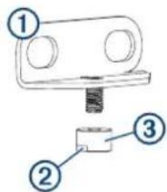
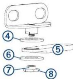
2 With the wrench flats ② on the bushing pointing away from the bracket, screw the bushing ③ onto the threaded rod on the bracket.
3 Using an 11 mm ( ^7/_16 in.) wrench, tighten the bushing onto the bracket.
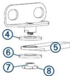
4 Place a nylon washer ④ over the bushing on the bracket.
5 With the notched end of the linkage arm facing away from the bracket, place the linkage arm cover the bushing on the bracket.
6 Place the other nylon washer cover the bushing on the bracket.
7 With the narrow end of the nut ⑦ facing towards the bracket, screw the nut ⑧ onto the end of the threaded rod.
8 Using a 15 mm ( ^19/_32 in.) wrench, tighten the nut to secure the linkage arm to the bracket.
Installing the Motor Bracket on the Motor
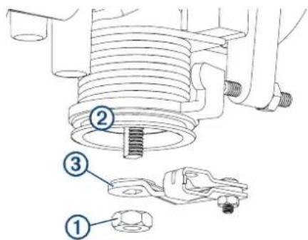
The assembled bracket and linkage arm must be installed between the tiller arm and steering mount on the motor.
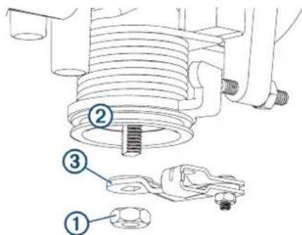
1 Remove the nuts that secure the tiller arm ① to the steering mount ② so you have access to the bolts . ③
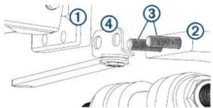
2 Place the assembled bracket and linkage arm ④ over the bolts on steering mount, and hold it in place.
3 Using the nuts you removed in the first step, secure the tiller arm and bracket to the steering mount.
Connecting the Linkage Arm to the Steering Actuator After you connect the linkage arm to your kicker motor tiller arm using the appropriate bracket, you must connect it to the steering actuator.
1 Screw the linkage pin into the end of the steering actuator rod, and secure it with the lock nut ②
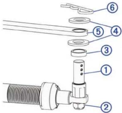
2 Referring to the diagram, install the spacer ③ washers , ④ and linkage arm ⑤ onto the linkage pin.
NOTE: You can install an additional black spacer (included) on the linkage pin if needed to help level the linkage arm.
3 Push the R-pin through the hole on the linkage pin to secure the linkage arm.
Installing the Throttle Actuator
NOTE: To help understand how the throttle actuator installs on your particular motor manifold and connects to the throttle, you can view installation photographs online. Go to www.garmin.com/manuals/reactorkicker.
1 Consult the Reactor 40 Kicker Throttle Actuator Installation Instructions provided in the corepack to understand the mounting and connection requirements of the throttle actuator.
2 Using the parts in this adapter kit, assemble the throttle linkage (Assembling the Throttle Linkage, page 3).
3 Connect the throttle actuator cable to the throttle linkage (Connecting the Throttle Actuator Cable to the Throttle Linkage, page 3).
4 Assemble the parts in this adapter kit and secure them to the motor (Throttle Actuator Component Connections, page 3).
5 Using the Reactor 40 Kicker Throttle Actuator Installation Instructions, complete and test the throttle actuator installation.
Assembling the Throttle Linkage
The throttle linkage allows the throttle cable from the actuator to pull open the throttle lever on the motor.
1 Using the parts provided in this adapter kit, place the throttle linkage bracket ① on the tapered end of the throttle linkage arm ②
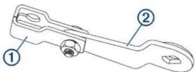
2 Using the bolt and nut provided in this adapter kit, fasten the bracket to the arm.
3 Tighten the nut so the bracket is securely connected to the arm, but loose enough so the bracket moves freely.
Connecting the Throttle Actuator Cable to the Throttle Linkage
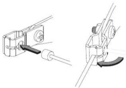
The throttle linkage is designed to hold the cable from the throttle actuator securely. Because of the design, you must connect the throttle actuator cable to the throttle linkage before you secure the parts to the motor.
1 If necessary, assemble the throttle linkage (Assembling the Throttle Linkage, page 3).
2 Place the round end of the throttle actuator cable into the hole on the end of the throttle linkage.
natural_image
Technical line drawing of two mechanical clamping tools (no text or symbols present)3 Rotate the cable so it feeds through the slot on the end of the linkage.
Throttle Actuator Component Connections
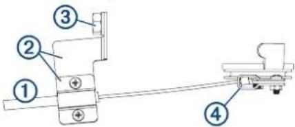
| Part Notes | |
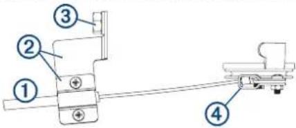
| 1Throttle actuator cable(from the throttle actuator box) | You should connect the throttle actuator cable to the throttle control linkage 4before securing it to the throttle cable bracket 2Connecting the Throttle Actuator Cable to the Throttle Linkage, page 3). |
| 2Throttle cable bracket | You must secure the throttle actuator cable 1to the throttle cable bracket using the included screws (Securing the Throttle Actuator Cable to the Bracket, page 3). |
| Part Notes | |
| 3Manifold mounting location | You must remove the existing bolt on the manifold and use it to secure the throttle cable bracket 2 |
| 4Throttle control linkage | You must assemble the throttle control linkage before installing it (Assembling the Throttle Linkage, page 3). You must use extreme care when removing the nut on the bottom of the throttle control wheel and spring. If the spring falls off, it can unwind and may be difficult to reinstall (Securing the Throttle Control Linkage to the Throttle Control Wheel, page 3). |
Securing the Throttle Actuator Cable to the Bracket
Before securing the cable to the bracket, you should connect the end of the throttle actuator cable to the throttle linkage (Connecting the Throttle Actuator Cable to the Throttle Linkage, page 3).
1 Place the top of the bracket ① over the raised portion of the throttle actuator cable ②
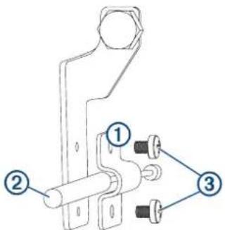
2 Secure the cable to the bracket using the included screws ③
Securing the Throttle Control Linkage to the Throttle Control Wheel
You must assemble the throttle control linkage before installing it (Assembling the Throttle Linkage, page 3).
1 Taking care that it does not fall into the motor housing, remove the 10 mm nut at the bottom of the throttle control wheel and spring and hold the spring so it does not slide down the throttle shaft.
NOTE: You must use extreme care when removing the nut on the bottom of the throttle control wheel and spring. If the spring drops down and falls off of the throttle shaft, it can unwind and may be difficult to reinstall.
2 Apply a humidity-cured, ethyl-based thread-locking compound, such as LOCTITE 435, to the threads on the throttle shaft and to the 10 mm nut you removed in the first step.
NOTICE
Vibration from normal use may result in this nut falling off if you do not apply a thread-locking compound.
3 Place the assembled throttle control linkage ③ on the throttle shaft.
The throttle control linkage arm is keyed to fit only one way on the throttle control wheel.
4 Secure the throttle control linkage to the throttle control wheel using the 10 mm nut you removed in the first step.
Setting the Linkage Components for Proper Idle
After you install the throttle actuator components on the motor, you must adjust them so the motor idles correctly.
1 Loosen the throttle actuator bracket on the engine manifold until the throttle actuator does not pull open the throttle lever. There should be obvious slack in the throttle actuator cable.
2 Adjust the tiller throttle to idle, start the motor, and complete an action:
- If the motor is not idling correctly, loosen the set screw on the throttle lever, adjust the tiller throttle linkage rod until the motor idles correctly, and tighten the set screw. - If the motor idles correctly, proceed to the next step.
3 Using the tiller throttle, increase the speed of the motor, and complete an action:
- If the motor does not increase its speed and return to idle correctly, repeat the previous step to adjust the tiller throttle linkage rod. - If the motor increases its speed and returns to idle correctly, proceed to the next step.
4 Adjust the position of the throttle actuator bracket until no slack remains in the throttle actuator cable and the motor idles correctly.
5 Tighten the throttle actuator bracket on the engine manifold to set the cable tension.
6 If necessary, turn off the motor.
natural_image
Technical illustration of two mechanical clamping or mounting mechanisms (no text or symbols)Référence Remarques
natural_image
Technical line drawing of two mechanical clamping tools (no text or symbols present)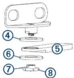
natural_image
Technical line drawing of two mechanical clamping tools (no text or symbols present)natural_image
Technical line drawing of two mechanical clamping tools (no text or symbols present)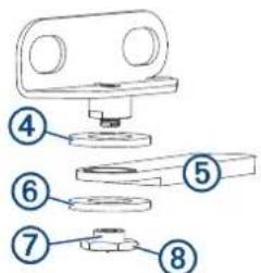
natural_image
Technical line drawing of two mechanical clamping tools (no text or symbols present)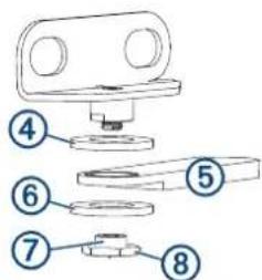
natural_image
Technical line drawing of two mechanical clamping tools (no text or symbols present)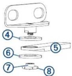
natural_image
Technical line drawing of two mechanical clamping tools (no text or symbols present)natural_image
Technical line drawing of two mechanical clamping devices (no text or symbols)Osa Huomautuksia
Securing the Throttle Actuator Cable to the Bracket
2 Med hakket ②vendt bort fra braketten skrur du hylsen gjengestangen på braketten.
3 Bruk en skrunøkkel på 11 mm ( ^7/_16 tommer) til å stramme til hylsen på braketten.
2 Monter avstandsstykket ③ skivene og leddkoblingsarmen ⑤ på leddkoblingsbolten i henhold til diagrammet.
natural_image
Technical line drawing of two mechanical clamping devices with no visible text or symbolsnatural_image
Technical line drawing of two mechanical clamping devices with no visible text or symbolsDel Meddelanden
natural_image
Technical line drawing of two mechanical clamping tools (no text or symbols)Część Uwagi
2 Sa zaravnanim dijelovima za ključ ②na ležaju okrenutima suprotno od nosača, pričvrstite ležaj ③na navojnu šipku na nosaču.
3 Zategnite ležaj na nosač s pomoću ključa od 11 mm (7/16 in).
4 Postavite crnu najlonsku podložnu pločicu ④na ležaj na nosaču.
5 S urezanim krajem ručice polužja okrenutim suprotno od nosača, postavite ručicu polužja na ležaj na nosaču.
6 Postavite drugu najlonsku podložnu pločicu ma ležaj na nosaču.
7 S uskim krajem matice Ⓞkrenutim prema nosaču, pričvrstite maticu ⓝna završetak navojne šipke.
8 Zategnite maticu s pomoću ključa od 15 mm ( ^19/_32 in) da biste pričvrstili ručicu polužja na nosač.
2 Sukladno dijagramu montirajte umetak ③podložne pločice ④ i ručicu polužja ⑤na pin polužja.
NAPOMENA: Možete montirati dodatni crni umetak (isporučuje se) na pin polužja ako je potreban za izravnavanje ručice polužja.
2 Zategnite nosač na ručicu s pomoću vijka i matice iz kompleta adaptera.
3 Zategnite maticu tako da nosač bude čvrsto povezan s ručicom, ali i dovoljno labav da se može slobodno kretati.
natural_image
Technical line drawing of two mechanical clamping tools (no text or symbols present)3 Zarotirajte kabel kako biste ga proveli kroz utor na kraju polužja.
Priključci komponenata aktuatora regulatora
| Dio Bilješke | |
| 1Kabel aktuatoraregulatora (izkutije aktuatoraregulatora) | Trebate povezati kabel aktuatora regulatora s upravljačkim polužjem regulatora 4rije nego što gapričvrstite za nosač kabela regulatora 7Povezivanje kabela aktuatora regulatora s polužjem regulatora, stranica 39). |
| 2Nosač kabelaregulatora | Trebate pričvrstiti kabel aktuatora regulatora 1nanosač kabela regulatora pomoću isporučenih vijaka(Učvršćenje kabela aktuatora regulatora za nosač,stranica 39). |
| 3Mjesto montažerazdjelnika | Trebate ukloniti postojeći vijak na razdjelniku iupotrijebiti ga za učvršćenje nosača kabela regulatora 2 |
| 4Upravljačkopolužje regulatora | Trebate sklopiti upravljačko polužje regulatora prijenego što ga montirate (Sklapanje polužja regulatora,stranica 39).Morate biti posebno oprezni prilikom uklanjanjamatice na dnu upravljačkog kotača i opruge regulatora. Ako opruga padne, može se odviti i može bititeško ponovno je postaviti (Pričvršćivanje upravljačkog polužja regulatora na upravljački kotačregulatora, stranica 39). |
2 Pričvrstite kabel za nosač pomoću isporučenih vijaka ③
Pričvršćivanje upravljačkog polužja regulatora na upravljački kotač regulatora
Trebate sklopiti upravljačko polužje regulatora prije nego što ga montirate (Sklapanje polužja regulatora, stranica 39).
1 Pazeći da ne padne u kućište motora, uklonite maticu od 10 mm ①na dnu upravljačkog kotača i opruge regulatora , ② držite oprugu kako ne bi kliznula niz vratilo regulatora.
NAPOMENA: Morate biti posebno oprezni prilikom uklanjanja matice na dnu upravljačkog kotača i opruge regulatora. Ako opruga padne s vratila regulatora, može se odviti i može biti teško ponovno je postaviti.
2 Nanesite spoj za zabravljivanje na bazi etila koji se stvrdnjava u vlažnim uvjetima, kao što je LOCTITE 435, na navoje vratila regulatora i maticu od 10 mm koju ste uklonili u prvom koraku.
OBAVIJEST
Ako ne nanesete spoj za zabravljivanje, ta matica može pasti zbog vibracija uzrokovanih uobičajenom upotrebom.
3 Postavite sklopljeno upravljačko polužje regulatora ③na vratilo regulatora.
Ručica upravljačkog polužja regulatora pričvršćena je tako da se može postaviti na upravljački kotač regulatora samo u jednom smjeru.
4 Pričvrstite upravljačko polužje regulatora na upravljački kotač regulatora s pomoću matice od 10 mm koju ste uklonili u prvom koraku.
- Reactor™ 40 Kicker Yamaha® EFI Adapter Installation Instructions
- Getting Started
- CAUTION
- Installing the Steering Actuator
- Assembling the Motor Bracket and Linkage Arm
- Installing the Motor Bracket on the Motor
- Connecting the Linkage Arm to the Steering Actuator After you connect the linkage arm to your kicker motor tiller arm using the appropriate bracket, you must connect it to the steering actuator.
- Installing the Throttle Actuator
- Assembling the Throttle Linkage
- Connecting the Throttle Actuator Cable to the Throttle Linkage
- Throttle Actuator Component Connections
- Securing the Throttle Actuator Cable to the Bracket
- Securing the Throttle Control Linkage to the Throttle Control Wheel
- NOTICE
- Setting the Linkage Components for Proper Idle
- Priključci komponenata aktuatora regulatora
- Pričvršćivanje upravljačkog polužja regulatora na upravljački kotač regulatora
- OBAVIJEST
Brand : GARMIN
Model : Reactor 40 Kicker
Category : Uncategorized