
GS7010 - Tool BLAUPUNKT - Free user manual and instructions
Find the device manual for free GS7010 BLAUPUNKT in PDF.

| Product Type | Wood Garden Shredder |
| Model | GS7010 |
| Brand | Blaupunkt |
| Rated Power | 2600 W |
| Supply Voltage | 230-240 V ~50 Hz |
| No-Load Speed | 42 rpm |
| Max Branch Diameter | 40 mm |
| Weight | 26.5 kg |
| Sound Pressure Level (LpA) | 75.70 dB(A) |
| Measured Sound Power Level (LwA) | 88.40 dB(A) |
| Guaranteed Sound Power Level | 92 dB(A) |
| Waste Container Capacity | Not specified |
| Blade Type | Rotating cutting roller with stationary blade |
| Blade Clearance Adjustment | Manual via knob (clockwise to decrease gap, counterclockwise to increase) |
| Overload Protection | Automatic circuit breaker with reset button |
| Safety Features | Safety switch to prevent accidental restart, tank lock/safety switch |
| Intended Use | Shredding wood garden waste for composting |
| Protection Class | Class I (requires grounded outlet) |
| Power Cord Length | Not specified |
| Motor Direction Switch | For shredding mode and branch pulling |
| Included Accessories | Pusher, waste container, wheel shaft, wheel guards |
| Cleaning | Clean after each use; do not use solvents; keep ventilation slots clean |
| Maintenance | Check blade condition and screw tightness regularly; after first 2 hours, retighten bolts |
| Repairability | Only authorized service professionals; use only original accessories |
Frequently Asked Questions - GS7010 BLAUPUNKT
User questions about GS7010 BLAUPUNKT
0 question about this device. Answer the ones you know or ask your own.
Ask a new question about this device
Download the instructions for your Tool in PDF format for free! Find your manual GS7010 - BLAUPUNKT and take your electronic device back in hand. On this page are published all the documents necessary for the use of your device. GS7010 by BLAUPUNKT.
USER MANUAL GS7010 BLAUPUNKT
natural_image
Blue and black industrial power plant with a red-handled wheels, no visible text or symbolsEnjoy it.
natural_image
Technical line drawing of a mechanical device with internal components and a wheel (no text or symbols)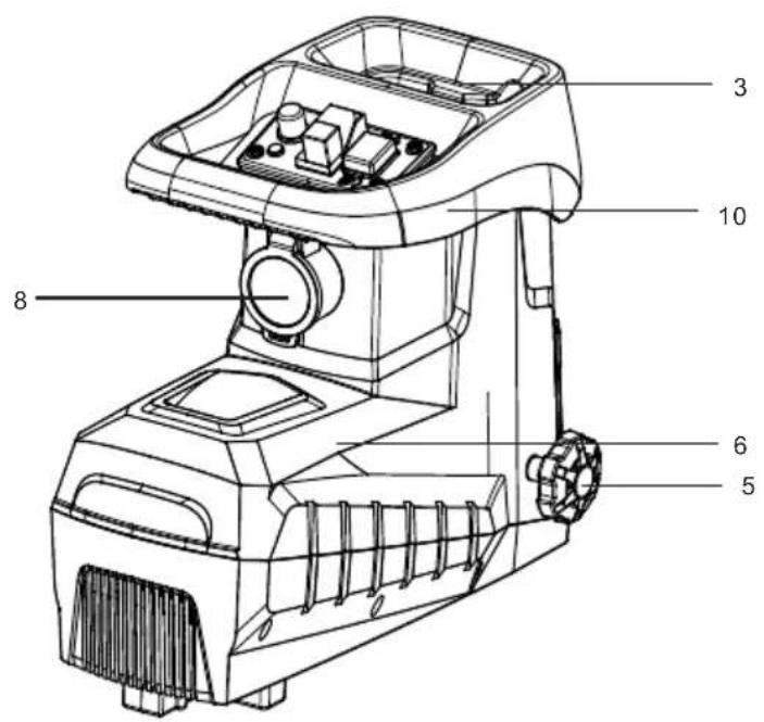
IMPORTANT INFORMATION
To achieve the highest satisfaction, enjoy the product's performance and learn about all its features and functions, please read this manual before using the product.
Before using the device, read the Operating Instructions and comply to its contents. The manufacturer shall not be liable for any damage caused by the use of the device other than for its intended purpose or by improper handling.
Keep these Operating Instructions for future reference.
- This device is for domestic use only. Do not use for any other purposes.
- The device should only be connected to an socket with values corresponding to the values on the rating label.
- It is necessary to check, if total current consumption of all devices plugged into the wall outlet does not exceed the fuse in the circuit.
- If you are using an extension cord, make sure that the total power consumption of the equipment plugged into the extension cord does not exceed the extension cord power rating. Extension cords should be arranged in such a way as to avoid tripping hazards.
- Do not let cord hang over edge of counter, or touch any hot surface.
- The device is not designed to be controlled via an external timer, separate remote control, or other equipment that can turn the device on automatically.
- Before maintenance work always disconnect the unit from the power supply.
-
When unplugging the power cord from electrical outlet, hold it by the plug only and remove the plug carefully. Never pull the cable as it may cause damage to the plug or power cord. Damage to the power cord or plug can lead to an electrocution hazard.
-
Never leave the product connected to the power source without supervision.
- Never put the power cable, the plug or the whole device into the water or any other liquids.
- The device should be cleaned regularly complying with the recommendations described in the section on cleaning and maintenance.
- Do not place the device near sources of heat, flame, an electric heating element or a hot oven. Do not place on any other device.
- The appliance must not be used by children. Keep the appliance and its cord out of the reach of children.
- The appliance may be used by individuals with limited physical, sensory or mental capability as well as those without knowledge of or previous experience in the use of similar appliances, provided such individuals are supervised or instructed with regard to the safe operation of the appliance and are informed about the potential hazards.
• Additional precautions should be taken when using this device in the presence of children or pets. Do not allow children to play with the device. - Never use the product close to combustibles.
- Never expose the product to atmospheric conditions such as direct sun light or rain, etc... Never use the product in humid conditions (like bathroom or camping house).
- The power cable should be periodically checked for damage. If the power cable is damaged the product should be taken to a professional service location to be fixed or replaced to prevent any hazards from arising.
- Never use the product with a damaged power cable or if it was dropped or damaged in any other way or if it does not work properly. Do not try to repair the defected product by yourself as it can lead to electric shock. Always return the damaged device to a professional service in order to repair it.
All the repairs should only be performed by authorized service professionals. Any attempted unauthorised repairs performed can be a hazard to the user.
- Only Original accessories should be used, as well as accessories recommended by the manufacturer. Using accessories which are not recommended by the manufacturer may result in damage of the device and may render the device unsafe for use.
- Keep your workplace tidy and well lit.
• Disorder and insufficient lighting lead to accidents.
- Do not use power tools in explosive atmospheres, i.e. in the presence of flammable liquids, gases or dust.
- A moment of carelessness may cause losing control of your tool.
- If it is possible to fit power tools for dust extraction or collection, check that they are fitted and working correctly. Using such power tools reduces the risk posed by the presence of dust.
- Do not lean out too far when working with your power tool. Maintain a stable posture and balance. This allows you to keep better control of your power tool in unforeseen situations.
- Avoid starting the power tool unintentionally. Make sure the power switch is in the OFF position before connecting the power tool to the mains. Carrying a power tool with your finger on its trigger or plugging in a power tool after switching it on can lead to accidents.
- Wear appropriate clothing. Do not work in loose clothing and do not wear jewellery while working. Keep your hair, clothing and gloves away from moving parts. The moving parts of a power tool can catch and pull in loose pieces of clothing, jewellery or long hair.
- Remove any spanners or tools from the power tool before starting it. A tool or spanner still connected to the rotating
part of the power tool may cause personal injury.
- Be careful when working with power tools, concentrate on your work and use common sense. Do not use a power tool when tired or under the influence of drugs, alcohol or medication. Even a moment of carelessness while working with a power tool can lead to a serious accident.
- Keep children away from the work area and DO NOT allow children to pull on the power cord - this can cause serious injury.
- Before making any adjustments, changing accessories or storing the power tool, move the switch to the off position to disconnect the power tool from the power supply. Such precautions reduce the risk of accidentally starting the power tool.
- Ensure that the vents are free from debris.
- The device may only be used in a dry, well-lit environment.
• This tool should not be used by anyone under the age of 16.
Electrical safety
- Connect the device only to an electrical supply of characteristics in accordance with the information on the data plate.
- The power tool plugs must match the power sockets. Never alter the power cord plug in any way. Unmodified plugs and suitable electrical sockets reduce the risk of an electric shock.
- Avoid touching grounded or shorted to ground surfaces such as piping, radiators, radiators and refrigerators. If parts that are grounded or shorted to ground are touched, the risk of electric shock increases.
- Do not expose electric devices to rain or humid conditions. If water enters the power tool, the risk of an electric shock increases.
- Do not tighten the connection cables. Never use the connection cable to carry, pull electrical equipment or pull the
plug out of the socket. Keep the connection cable away from heat sources, oils, sharp edges or moving parts. Damaged or entangled connection cables increase the risk of an electric shock.
- Before starting the work, check the power cord before starting the work. Do not operate if the power cord or extension cord is abraded, cut or otherwise damaged. If the power cord is damaged during use, switch off the device and unplug it from the socket.
- If the power tool is used outdoors, the connection cables should be extended with waterproof extension cords designed to operate outdoors. Using such an extension cord reduces the risk of an electric shock. The cross-section area of the extension cord conductors should be at least 1.5 mm ^2 when the length of the cable is less than 20 m, and if the length of the cable is between 20 and 50 m, the minimum cross-section is 2.5 mm. ^2
- A residual current protection device (RCD) must be used as protection against shock from the supply voltage. Using the RCD reduces the risk of electric shock. The equipment should be supplied through an RCD with a rated current not exceeding 30 mA.
General information
- The device is intended for house gardening use only as described and protected by these instructions for use
- Do not put your hands into the shredder while in operation. The blades still move for a few seconds after switching off.
- Make sure that no people are present around the machine. Foreign bodies and debris may be ejected while the machine is in operation.
 | Read the user manual. |  | Use ear protection |
 |  | Wear protective glovesGeneral warning | |
 | Fire hazard |  | Wear protective clothing |
 | Electric shock hazard |  | Wear a protective mask |
 | Wear safety glasses |  | Wear respiratory protection |
SYMBOLS
- The following symbols may appear in the operating instructions or on the tool's nameplate.
• These signs contain important information about the product and instructions on how to use it.
When this crossed-out wheeled bin symbol is attached to a product it means that the product is covered by the European Directive 2012/19/EU. Please inform yourself about the local separate collection system for electrical and electronic products. Used appliance should be delivered to the dedicated collecting points due to hazardous components, which may affect the environment. Do not dispose this appliance in the common waste bin.

Your products is designed a manufactured with high quality materials and components, which can be recycled and reused.
Intended use:
This device is designed for shredding wood garden waste for composting. The hopper is intended for the collection and storage of the shredded material. Do not use the waste hopper for other purposes.
WEAR PERSONAL PROTECTIVE EQUIPMENT
- Wear safety glasses according to En166
- Use protective masks in accordance with En149
- Use other types of proper personal protective equipment, depending on the type of work involved.
Description of the device
- Waste container
- Tank lock/safety switch
- Loading opening
- Circle
- Appliance body
- Blade pressure control knob
- Pusher
-
Power cord
-
Appliance frame
- Handle
- Frame
- Power on button
- Blade rotation direction switch button.
- Power off button
- Overload fuse
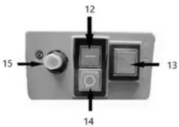
Control panel description:
1) Green button starts the shredder
2) Red button "14": stop the shredder
Note: the machine is equipped with a safety switch to prevent accidental switching on after a power failure
The motor direction switch "13" switch the button up in order for the motor to work in the shredding mode.
2) Button 13 in the direction of: down press the button 13 down to start the branch pulling.
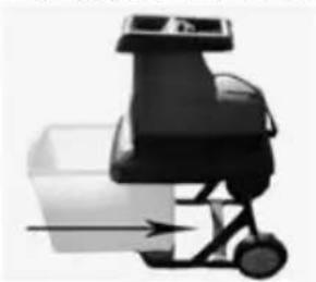
When the waste container is full:
1) press the red "14" button
2) Move the container locking switch
3) Remove the waste container
4) Empty and slide back
Open the packaging and remove the machine from it. Pull out the waste container and remove the main part of the machine and accessories.
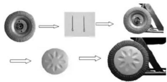
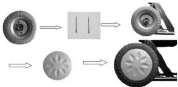
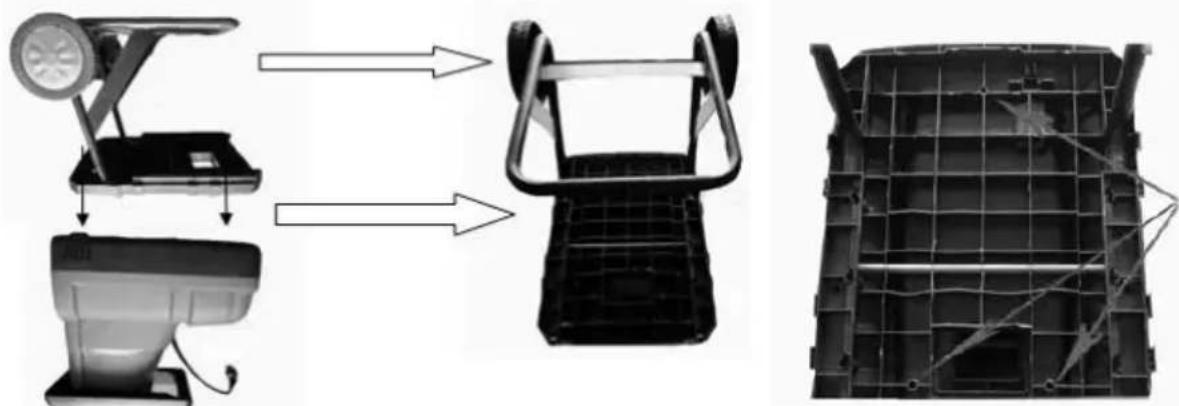
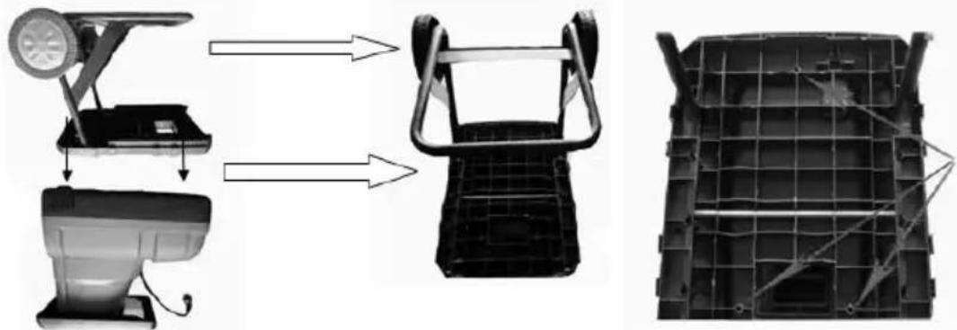
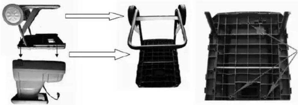
Wheel shaft assembly
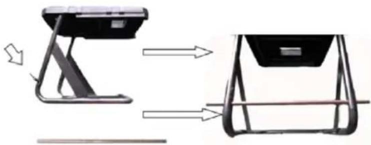
natural_image
Diagram showing a device being assembled from a stand to a back panel, with arrows indicating the process (no text or symbols present)Wheel and wheel guard installation:
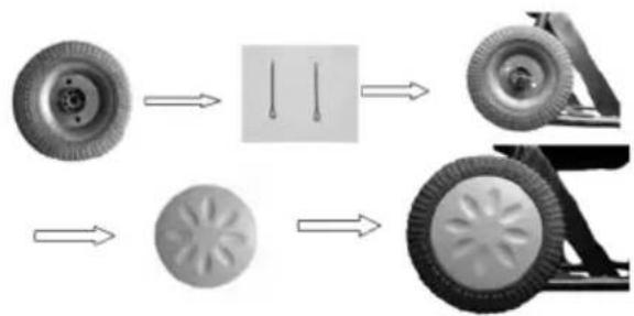
flowchart
graph LR
    A["Wheel"] --> B["Diagram of two pins"]
    B --> C["Wheel rim"]
    C --> D["Wheel rim with gear-shaped components"]
    D --> E["Wheel rim with gear-shaped components"]
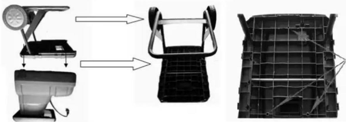
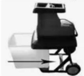
Installation

natural_image
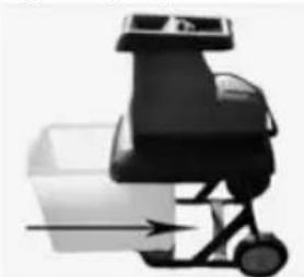
Three-panel diagram showing a motor, fan, and internal components with arrows indicating assembly or transformation (no text or symbols)Waste container installation
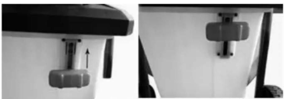
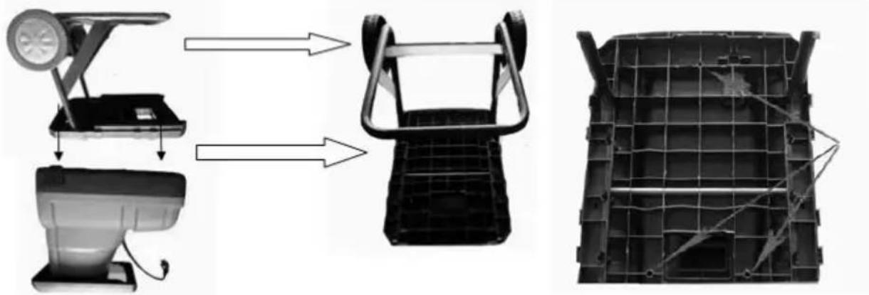
natural_image
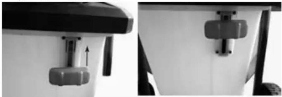
Mechanical device with a rotating base and directional arrow, no visible text or symbolsThe gear lock must be secured
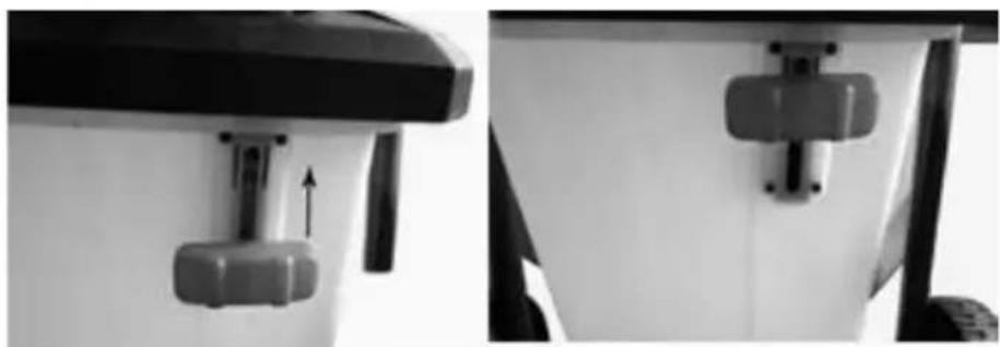
natural_image
Close-up of a mechanical component with a downward arrow indicating a force or movement (no text or symbols visible)Blade clearance adjustment
To ensure optimum operation of the shredder, set the clearance between the stationary blade and the cutting roller by means of the blade pressure adjustment knob. Setting the clearance:
- Turn on the machine.
- Turn the adjustment knob counter clockwise to increase the distance of the stationary blade to the cutting roller
- Turn the adjustment knob clockwise to bring the stationary blade closer to the cutting roller.
- It is recommended to control the blade pressure while the machine is in operation. The required pressure may be different for the different cross-sections of the shredded branches.
MACHINE OPERATION
To start the shredder press the on/off switch to the position marked "I", to turn off press "0". Wait until the blades start to rotate at full speed before loading the material for shredding. Do not place the material in the loading tunnel when the machine is switched off or does not operate at full speed.
NOTE: The machine has an overload switch. The circuit breaker will be activated when the accumulated shredded material blocks the cutting discs, the load is too hard or thick and exceeds the motor capabilities, or there is too much resistance of the cutting blade. After removing the cause of the machine overload, press the reset button.
NOTE: Switch off the machine in the event that the blade hits a hard object or unusual noises or vibrations. Pull the plug out of the mains socket and do the following:
- inspect the blade and other components for damage;
- check for loose parts and tighten if necessary;
If necessary, contact an authorised service centre.
Shredding instructions
The hardness of branches and logs for shredding depends on the genre, age and degree of humidity of the wood. The most efficient is shredding of fresh branches, soon after cutting. Soft garden waste should be shredded in smaller batches, especially when it is moist. To prevent such material from blocking, occasionally crush thicker branches or logs.
The branches protruding from the machine may hit the operator when being pulled in; therefore, keep a safe distance!
Insert only an amount of material that does not block the shredder.
Damp or residual garden waste should be shredded alternately with thicker branches. This prevents the blade from overloading
Do not place compost-type soft waste in the shredder. This type of material should be composted as
such.
Care must be taken to ensure that the shredded material can escape freely through the outlet opening. There is a danger of blockage when too much material is loaded for shredding.
Empty the shredding hopper regularly. The hopper may not fill evenly.
Cleaning and maintenance
- After each use clean the entire device of plant residues and the lower cover of the collected compacted mass.
- Ventilation slots and motor housing should be kept free of dust and dirt, as much as possible. Wipe the device with a clean cloth, brush or purge with compressed air.
- It is recommended to clean immediately after every use.
- Do not use any cleaning agents or solvents to clean the device; they may damage the plastic parts. Take care not to allow water to enter the device.
- Check the condition of the cutting string regularly, as well as the tightening of the screws. With new devices, the bolt tightening should be checked after about 2 first hours of operation. Tighten the loosened bolts if necessary.
- Ensure that all components of the power tool are in good working order and do not overload or carry out any work for which the device is not intended.
Technical data:
Supply voltage: 230-240 V \~50Hz
Rated power: 2600W
Revolutions per min: 42
Max. blade length (mm): ∅40
Weight: 26.5kg
Noise and vibrations.
Noise and vibrations.
The noise and vibrations have been measured in accordance with EN ISO 3744:2010
Noise emission: Sound pressure level (LpA): 75.70 dB (A)
KpA deviation: 3.00 dB (A)
Measured sound power level LwA: 88.40 dB (A)
KwA deviation: 3.00 dB (A)
Guaranteed sound power level: LwA: 92 dB (A)
WAŻNE INFORMACJE
natural_image
Diagram showing a device being assembled into a larger frame, with arrows indicating the process (no text or symbols present)natural_image
Three-panel diagram showing a motor assembly process: top-down view, side-up view of a motor housing, and final assembled view (no text or symbols)natural_image
Mechanical device with motion arrow indicating movement (no text or symbols visible)natural_image
Close-up of a mechanical component with a metallic bracket and directional arrow indicator (no text or symbols)natural_image
Diagram showing a device being assembled into a larger frame, with arrows indicating process flow (no text or symbols present)natural_image
Diagram showing three stages of a vehicle's front panel assembly: engine, battery pack, and wheel cover (no text or labels)natural_image
Mechanical device with motion arrow indicating movement (no text or symbols visible)natural_image
Close-up of a mechanical component with a central knob and directional arrow, shown from two angles (no text or symbols visible)POUŽÍVAJTE OSOBNÉ OCHRANNÉ PROSTRIEDKY
natural_image
Diagram showing a mechanical device with two views and directional arrows indicating motion (no text or symbols)Montáž kolesa a krytu kolesa:
flowchart
graph LR
    A["Wheel"] --> B["Box with two pins"]
    B --> C["Wheel rim"]
    D["Wheel"] --> E["Gear-like Component"]
    E --> F["Wheel rim"]
    style A fill:#f9f,stroke:#333
    style D fill:#f9f,stroke:#333
    style B fill:#ccf,stroke:#333
    style C fill:#cfc,stroke:#333
    style E fill:#fcc,stroke:#333
    style F fill:#cff,stroke:#333
Montáž

natural_image
Exploded view diagram of a motor assembly and internal components (no text or symbols)natural_image
Mechanical device with motion arrow indicating movement (no text or symbols visible)natural_image
Close-up of a mechanical component with a bolt and adjustment knob, shown from two angles (no text or symbols visible)natural_image
Diagram showing a device being lifted from a stand to a seat, with arrows indicating motion direction (no text or symbols present)flowchart
graph LR
    A["Wheel"] --> B["Part with two pins"]
    B --> C["Wheel rim"]
    C --> D["Wheel rim with gear-like components"]
    D --> E["Wheel rim with gear-like components"]
Beszerelés
natural_image
Exploded view diagram of a car interior showing motor, fan, and frame components (no text or labels)natural_image
Mechanical device with motion arrow indicating movement (no text or symbols)natural_image
Close-up of a mechanical device with a lever and adjustment knob, shown from two angles (no text or symbols visible)natural_image
Diagram showing a device being assembled into a larger frame, with arrows indicating motion direction (no text or symbols present)natural_image
Exploded view diagram of a vehicle chassis showing internal components and structural details (no text or symbols)natural_image
Mechanical device with motion arrow indicating motion (no text or symbols visible)Zaklenite menjalnik blokade
natural_image
Close-up of a mechanical component with a downward arrow indicating a force or movement (no text or symbols visible)natural_image
Diagram showing a device with a left-side shift and right-side side view, illustrating mechanical assembly (no text or symbols)Ugradnja kotača i poklopca kotača:
flowchart
graph LR
    A["Wheel"] --> B["Part with two vertical holes"]
    B --> C["Wheel rim"]
    D["Wheel"] --> E["Part with four star-shaped holes"]
    E --> F["Wheel rim"]
    style A fill:#f9f,stroke:#333
    style D fill:#f9f,stroke:#333
    style B fill:#ccf,stroke:#333
    style C fill:#ccf,stroke:#333
    style E fill:#ccf,stroke:#333
    style F fill:#ccf,stroke:#333
Montaža
natural_image
Exploded view diagram of a mechanical device showing internal components and assembly (no text or symbols)Ugradnja spremnika za otpad
natural_image
Mechanical device with motion arrow indicating movement (no text or symbols visible)Zaključajte zupčanike za blokiranje

natural_image
Close-up of a mechanical device with a central knob and two side views showing internal components (no text or symbols visible)Podešavanje razmaka oštrice
Za optimalan rad sjeckalice, postavite razmak između nepomične oštrice i rezne osovine pomoću gumba za podešavanje pritiska oštrice. Postavka razmaka:
natural_image
Diagram showing a device with a stand and its side panel, illustrating the process of assembly or cleaning (no text or symbols present)flowchart
graph LR
    A["Wheel"] --> B["Box with two holes"]
    B --> C["Wheel rim"]
    D["Wheel"] --> E["Gear-like component"]
    E --> F["Wheel rim with gear-like components"]
Εγκατάστηση:
natural_image
Three-panel diagram showing a motor, battery pack, and internal components with no visible text or symbols.natural_image
Mechanical device with motion arrow indicating movement (no text or symbols visible)natural_image
Close-up of a mechanical component with a bolt and adjustment knob, shown from two angles (no text or symbols visible)natural_image
Diagram showing a device being lifted from a stand to a seat, with no visible text or symbols.natural_image
Three-panel diagram showing a motor, battery pack, and internal components with arrows indicating assembly or transformation (no text or symbols)natural_image
Mechanical device with a lever and wheels, showing motion direction (no text or symbols)natural_image
Close-up of a mechanical component with a metallic fitting and a directional arrow indicator (no text or symbols)natural_image
Diagram showing a device being assembled into a larger base frame, with arrows indicating motion direction (no text or symbols present)natural_image
Exploded view diagram of a mechanical device showing internal components and assembly (no text or symbols)natural_image
Mechanical device with motion arrow indicating movement (no text or symbols visible)Blocati angrenajele de blocare
natural_image
Close-up of a mechanical component with a downward arrow indicating a force or movement (no text or symbols visible)Reglarea distantei lamei
Lungimea max. a lamei (mm): ∅40
Greutate: 26,5kg
Zgomot și vibrații.
natural_image
Diagram showing a device being assembled from a stand to a backrest, with arrows indicating process flow (no text or symbols present)flowchart
graph LR
    A["Tire with circular head"] --> B["Component diagram with two vertical lines"]
    B --> C["Part of wheel"]
    C --> D["Assembly of tire parts"]
    D --> E["Final assembly state"]
Montavimas
natural_image
Three-panel diagram showing a cleaning or assembly process: top-down view of a pump, side-up view of a motor housing, and final assembled frame (no text or symbols)Atlieku konteinerio jrengimas

natural_image
Illustration of a mechanical device with motion arrow indicating movement (no text or symbols)natural_image
Close-up of a mechanical component with a downward arrow indicating a force or movement (no text or symbols visible)natural_image
Diagram showing a device with a slide and its side panel, illustrating the process of folding or assembly (no text or symbols present)Ratta ja ratta katte paigaldamine:

flowchart
graph LR
    A["Wheel"] --> B["Bracket with two holes"]
    B --> C["Wheel rim"]
    D["Wheel"] --> E["Star-shaped component"]
    E --> F["Wheel rim with four star-shaped features"]
Paigaldamine
natural_image
Three-panel diagram showing a motor, battery pack, and car chassis with structural details (no text or symbols)Jäätmemahuti paigaldamine
natural_image
Mechanical device with a cylindrical component and wheels, showing motion direction (no text or symbols)natural_image
Close-up of a mechanical component with a metallic knob and a directional arrow indicator (no text or symbols)natural_image
Diagram showing a device being assembled into a larger frame, with arrows indicating process flow (no text or symbols present)natural_image
Three-panel diagram showing a motor, battery pack, and internal components with arrows indicating assembly or transformation (no text or symbols)natural_image
Mechanical device with motion arrow indicating motion (no text or symbols visible)natural_image
Close-up of a mechanical device with a central knob and a pull rod, shown from two angles (no text or symbols visible)Maks. asmens garums (mm): ∅ 40
Svars: 26,5kg
EU – DECLARATION OF CONFORMITY
01/2022/GS7010
MANUFACTURER:
BLAUPUNKT COMPETENCE CENTER
2N-Everpol Sp. z o.o.
ul. Puławska 403A
02-801 Warsaw, Poland
Authorized person to prepare the technical documentation:
Tomasz Jakóbczyk
ul. Puławska 403A
02-801 Warsaw, Poland
We declare under our sole responsibility that our product:
Type of device:
Shredder
Name:
GS7010
If used for its intended use complies with the essential protection requirements relating to the:
2014/30/EU (EMC Directive)
2014/35/EU (LVD Directive)
2006/42/EC (MD Machinery Directive)
2011/65/EU (RoHS Directive) and its Annex II amending directive 2015/863/EU
The assessment of this product has been based on the following standards:
EMC standards:
EN 55014-1:2017+A11:2020 | EN IEC 55014-1:2021
EN 55014-2:2015 | EN IEC 55014-2: 2021
EN IEC 61000-3-2: 2019+A1:2021
EN 61000-3-3: 2013+A1:2019+A2:2021
MD and LVD standards:
EN 60335-1:2012 + A11:2014 + A13:2017 + A1:2019 +
A14:2019 + A2:2019 + A15:2021
EN 50434: 2014
RoHS standards:
IEC EN 63000:2018
Warsaw, 15.12.2022

BLAUPUNKT
02-801 Warsaw, Poland
Corespondence address:
Puławska 12
05-532 Baniocha, Poland
Phone +48 22 688 08 00
DEKLARACJA ZGODNOŚCI UE
01/2022/GS7010
PRODUCENT:
BLAUPUNKT COMPETENCE CENTER
2N-Everpol Sp. z o.o.
ul. Puławska 403A
02-801 Warszawa, Polska
02-801 Warsaw, Poland
phone:+48226880800
e-mail: info@everpol.pl
www.blaupunkt.com
In case of questions or problems please contact our service.
Tel. 00 48 22 688 08 33
Email:tools@blaupunkt.pl
Enjoy it.
All rights reserved. All brand names are registered trademarks of their respective owners. Specifications are subject to change without prior notice.