KNA-G421 - GPS Navigation System KENWOOD - Free user manual and instructions
Find the device manual for free KNA-G421 KENWOOD in PDF.
User questions about KNA-G421 KENWOOD
0 question about this device. Answer the ones you know or ask your own.
Ask a new question about this device
Download the instructions for your GPS Navigation System in PDF format for free! Find your manual KNA-G421 - KENWOOD and take your electronic device back in hand. On this page are published all the documents necessary for the use of your device. KNA-G421 by KENWOOD.
USER MANUAL KNA-G421 KENWOOD
Failure to avoid the following potentially hazardous situations could result in serious injury or fire.
- Do not attempt to install or service the KNA-G421 by yourself. Installing or servicing the unit without training and experience in electronic equipment and automotive accessories may be dangerous and could expose you to the risk of electric shock or other hazards.
- When extending ignition, battery, or ground wires, use automotive-grade wires or other wires with AWG 18 (0.75 mm ^2 gauge) or greater to prevent wire deterioration and damage to the wire coating.
- If the unit starts to emit smoke or strange smells, turn off the power immediately and consult your Kenwood dealer.
- Keep small articles (like screws or batteries) out of the reach of children. If any such object is accidentally swallowed, consult a doctor immediately.

Caution
Failure to avoid the following potentially hazardous situations may result in injury or property damage.
- Make sure to ground the unit to the chassis of your vehicle.
- Secure all wiring with cable clamps or electrical tape. Insulate unconnected wires; do not allow any bare wiring to remain exposed.
- Do not let unconnected wires or terminals touch metal on the vehicle or anything else that can conduct electricity.
- Do not open the top or bottom covers of the unit.
• The KNA-G421 is not waterproof.
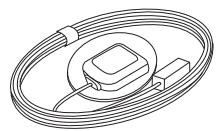
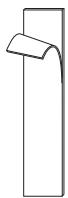
GPS antenna and metal plate
natural_image
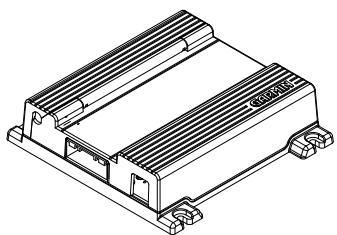
Isometric line drawing of a rectangular electronic component with heat sinks and mounting feet (no text or symbols)main unit

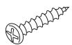
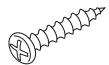
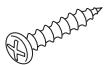
screws (4)
natural_image
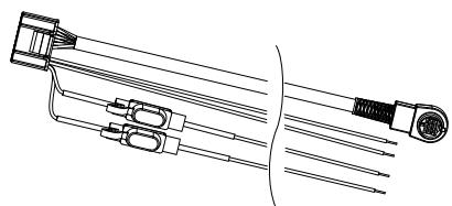
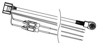
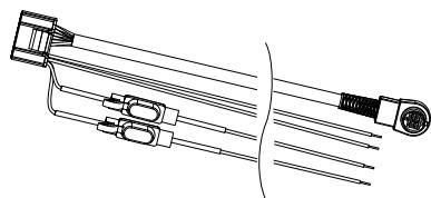
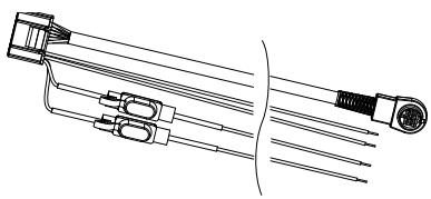
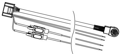
Technical line drawing of a mechanical component with multiple ports and connectors (no text or symbols)wiring harness

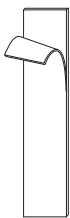
hook and loop fasteners (2)
Installing the Main Unit
Use the screws or the hook and loop fasteners provided to mount the main unit in the vehicle. Select a location that allows you to access the unit's SD card slot. Be sure to place the unit horizontally (flat) and secure it completely for best performance.
Caution
- Do not install the unit where it will be exposed to direct sunlight, excessive heat or humidity, dust, spills, or liquids. Use only the screws provided. If you use the wrong screws, you could damage the unit.
- Check for cables or other parts underneath the floor mat before cutting the floor mat.
Installing the GPS Antenna
Caution
- Do not paint the antenna. This will impair or disable signal reception.
- Remove any object or accumulated snow, etc., from the top of the antenna. It will reduce reception strength.
- Do not pull the cord when removing the antenna or adjusting its position. This can cause a short or snap the wires.
- The permanent adhesive on the back of the metal plate is extremely difficult to remove after it is installed.
The GPS antenna can be installed either inside or outside the vehicle. It should be placed horizontally for best GPS reception. The GPS antenna must have a clear view of the sky. If you install the antenna inside the vehicle, place it close to a window; GPS signals can pass through glass but not through metal. Refer to the image on the next page for recommended places to install the antenna. Place the GPS antenna on a metallic surface, such as the roof of your vehicle, for best reception. If a metallic surface is not available, mount the GPS antenna to the enclosed metal plate. See the next page for further instructions.
Installing Optional Accessories
For information on installing the optional FM traffic receiver (such as the GTM 10), refer to the installation guide included with the traffic receiver.
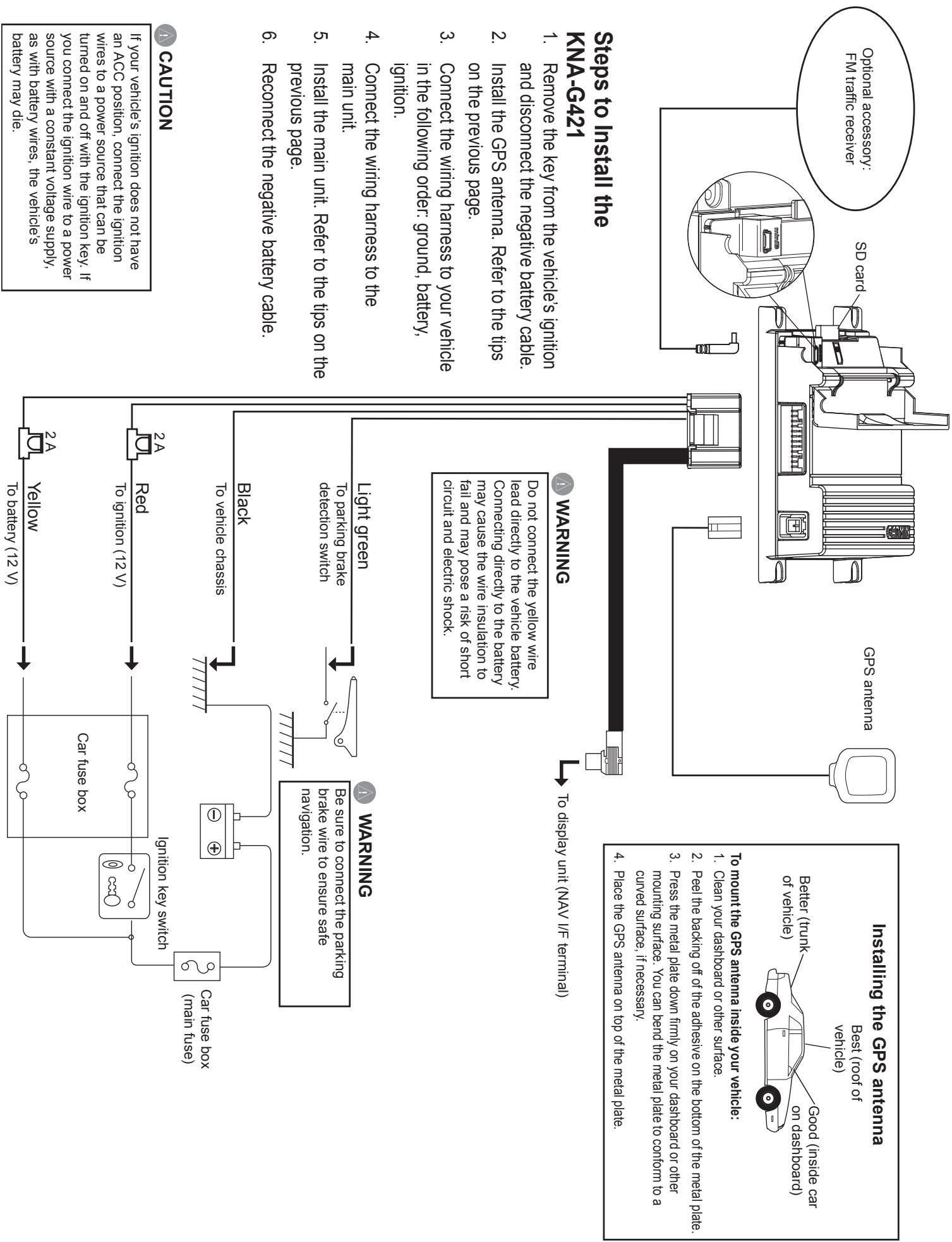
- Reconnect the negative battery cable.
previous page.
- Install the main unit. Refer to the tips on the
main unit.
- Connect the wiring harness to the
ignition.
- Connect the wiring harness to your vehicle in the following order: ground, battery,
on the previous page.
- Install the GPS antenna. Refer to the tips
and disconnect the negative battery cable.
- Remove the key from the vehicle's ignition
KNA-G421
Steps to Install the
Do not connect the yellow wire lead directly to the vehicle battery. Connecting directly to the battery may cause the wire insulation to fail and may pose a risk of short circuit and electric shock.
WARNING
To display unit (NAV I/F terminal)
- Peel the backing off of the adhesive on the bottom of the metal plate.
- Press the metal plate down firmly on your dashboard or other mounting surface. You can bend the metal plate to conform to a curved surface, if necessary.
- Place the GPS antenna on top of the metal plate.
Acquiring GPS Signals
The first time you turn on the KNA-G421, you must wait while the system acquires satellite signals for the first time. This process could take up to several minutes. Make sure your vehicle is outdoors in an open area away from tall buildings and trees for fastest acquisition. After the system acquires satellites for the first time, it will acquire satellites quickly each time thereafter.
Changing the Fuses
If you need to replace a fuse on the red or yellow wires, make sure the wires are not touching to prevent a short circuit. Then replace the old fuse with a new 2 Amp fuse.

Caution
When replacing a fuse, use only a new fuse with the prescribed rating. Using a fuse with the wrong rating may cause your unit to malfunction. Disconnect the wiring harness before replacing a fuse to prevent short circuits.
Specifications
General
Operating Temperature: -15°C to 70°C
Storage Temperature: -40°C to 85°C
Operating Voltage: 9.5 V to 25 V
Current Consumption: 0.13 A typical at 13 V (Max 1.0 A at 13 V)
ACC off Current: 60 uA typical at 13 V
Dimensions: 30 mm H x 120 mm W x 117 mm L
Weight: 184 g
Map Storage: Internal non-removable memory and optional removable SD card (City Navigator™ map data)
Connectors: System/power, GPS antenna, SD card slot, Mini-B for optional FM traffic receiver
Navigation
Receiver: SiRF STAR III high-sensitivity GPS receiver
Frequency: 1,575.42 MHz
Acquisition Times\*:
Warm: < 1 second
Cold: < 38 seconds
AutoLocate®: < 45 seconds
*On average for a stationary receiver with an open sky view
Update Rate: 1/second, continuous
GPS Accuracy:
Position: < 10 meters, typical
Velocity: 0.05 meter/sec RMS
DGPS (WAAS) Accuracy:
Position: < 5 meters, typical
Velocity: 0.05 meter/sec RMS
Antenna: External GPS antenna requires metal surface 60 mm x 60 mm or larger, such as a car roof or the included metal plate. A larger metal mounting surface improves GPS reception.
KENWOOD
MANUEL D'INSTALLATION
Kenwood Corporation

text_image
Tyuyu-sho Kyoubshs Tyuyu St Kandyou-Berl Kandyou-Berl Mishan Bagh -hai Portugama Lih B'kat (gushi) Bridel -shou Gyumida-Phe
Avertissement
natural_image
Isometric line drawing of a rectangular electronic component with heat sinks and mounting feet (no text or symbols)unité principale

vis (4)
natural_image
Technical line drawing of a mechanical component with multiple rods and connectors (no text or symbols)faisceau de câbles
fermetures
autoagrippantes (2)
natural_image
Isometric line drawing of a heat exchanger or cooling unit (no text or symbols)unità principale
viti (4)
natural_image
Technical line drawing of a mechanical component with no visible text or symbolsnatural_image
Isometric line drawing of a heat exchanger or cooling unit (no text or symbols)Haupteinheit

Schrauben (4)
natural_image
Technical line drawing of a mechanical component with multiple rods and a cylindrical end (no text or symbols)Kabelbaum
Klettverschlüsse
(2)
natural_image
Isometric line drawing of a rectangular electronic component with heat sinks and mounting feet (no text or symbols)unidad principal
tornillos (4)

natural_image
Technical line drawing of a mechanical component with multiple ports and connectors (no text or symbols)arnés de cableado
cierres de enganche
y giro (2)
natural_image
Isometric line drawing of a rectangular electronic component with heat sinks and mounting feet (no text or symbols)unidade principal
parafusos (4)

natural_image
Technical line drawing of a mechanical component with multiple rods and connectors (no text or symbols)cablagem
text_image
Tyayou-she Kyudubighi Tyayou Bt Kandyou-barl Metbel-Shou Miyakei Purugamis Lih 10 Bikai jujishi Gumbel-Phe
Waarschuwing
natural_image
Isometric line drawing of a rectangular electronic component with heat sinks and mounting feet (no text or symbols)hoofdeenheid

schroeven (4x)
natural_image
Technical line drawing of a mechanical component with multiple ports and a cylindrical end (no text or symbols)kabelboom
klittenband (2x)