
J-HANDLE - Garden tools HUSQVARNA - Free user manual and instructions
Find the device manual for free J-HANDLE HUSQVARNA in PDF.

| Product type | J-handle kit for brushcutter |
| Brand | HUSQVARNA |
| Model | J-HANDLE |
| Kit contents | 1 J-handle, 1 weed blade guard, 1 weed blade, 1 glide cup |
| Material | Steel and reinforced plastic |
| Blade center hole diameter | 20 mm |
| Blade shaft thread | M10 |
| Compatible blade type | Weed blade/knife (Grass 255-4, 255-8, Multi 255-3) |
| Compatible cutting head type | Tricut, Trimmy Fix, Trimmy HitPro, Superauto II, Trimmy HII |
| Recommended guard | Ref. 503 74 40-01 for blades, 503 74 50-04 for plastic heads |
| Main function | Brushing and weeding with improved ergonomics |
| Transport position | Foldable handle along the tube |
| Maintenance and cleaning | Clean after use, sharpen blades regularly, inspect for cracks |
| Safety | Use only with recommended guard; do not mount saw blade; stop engine before cleaning |
| Assembly instructions | Mount the handle on the tube, then the blade and guard according to the manual |
| Nut tightening torque | 35-50 Nm (3.5-5 kpm) |
| Repairability | Spare parts available: guards, blades, nuts; consult manual or Husqvarna after-sales service |
| General information | Kit complement to the machine manual; always read the user manual before use |
Frequently Asked Questions - J-HANDLE HUSQVARNA
User questions about J-HANDLE HUSQVARNA
0 question about this device. Answer the ones you know or ask your own.
Ask a new question about this device
Download the instructions for your Garden tools in PDF format for free! Find your manual J-HANDLE - HUSQVARNA and take your electronic device back in hand. On this page are published all the documents necessary for the use of your device. J-HANDLE by HUSQVARNA.
USER MANUAL J-HANDLE HUSQVARNA
SE Bruksanvisning J-handtagssats

VIKTIG INFORMATION

WARNING!

WARNING!
Kontroll före start
VIKTIG INFORMASJON
Transportstilling, J-håndtak

ADVARSEL!
Kontroll før start
TEKNISKE DATA
| Godkjente tilbehør J-håndtak | Type | Skjerm for skjæreutstyr, Art. nr |
| Sentrumshull i blader/kniver ∅ 20 mmGjenge bladaksel M10 | ||
| Gressblad/gresskniv | Grass 255-4 (∅ 255 4-tannet) | 503 74 40-01 |
| Grass 255-8 (∅ 255 8-tannet) ikke 240L | 503 74 40-01 | |
| Multi 255-3 (∅ 255 3-tannet) | 503 74 40-01 | |
| Plastkniver | Tricut ∅ 300 | 503 74 50-04 |
| Trimmerhode | Trimmy Fix | 503 74 50-04 |
| Trimmy Hit Pro | 503 74 50-04 | |
| Superauto II | 503 74 50-04 | |
| Trimmy HII | 503 74 50-04 | |
| Støttekopp | Fast | - |
VIGTIG INFORMATION

ADVARSEL!
Transportstilling, J-håndtag
Montering af klinge og trimmerhoved

ADVARSEL!
Kontrol før start


TEKNISKE DATA
TÄRKEÄ TIETÄÄ


VAROITUS!

Kuljetusasento, J-kahva

VAROITUS!

TEKNISET TIEDOT

WARNUNG!

WARNUNG!


ATENÇÃO!

ATENÇÃO
ESPECIFICAÇÕES TÉCNICAS


ATENCIÓN

ATENCIÓN

WAARSCHUWING!
Transportpositie, J-handvat

WAARSCHUWING!

TECHNISCHE GEGEVENS
| Goedgekeurde accessoires J-handvatCentrumopening in maabladen/messen ∅ 20 mmSchroefdraad maabladas M10 | Type | Beschermkap voor de snijuitrusting. Artikelnr. |
| Grasblad/grasmes | Grass 255-4 (∅ 255 4-punts) | 503 74 40-01 |
| Grass 255-8 (∅ 255 8-punts) 240L niet | 503 74 40-01 | |
| Multi 255-3 (∅ 255 3-punts) | 503 74 40-01 | |
| Kunststof messen | Tricut ∅ 300 | 503 74 50-04 |
| Maakop | Trimmy Fix | 503 74 50-04 |
| Trimmy Hit Pro | 503 74 50-04 | |
| Superauto II | 503 74 50-04 | |
| Trimmy HII | 503 74 50-04 | |
| Steunkop | Vast | - |

INFORMATIONS IMPORTANTES

AVERTISSEMENT!

AVERTISSEMENT!


ATTENZIONE!

ATTENZIONE!

DATI TECNICI
| Accessori omologati Impugnatura a J | Tipo | Corprilama Art. no. |
| Foro centrale lame/coltelli: ∅ 20 mm | ||
| Passo albero lama: M10 | ||
| Lama tagliaerba/Coltello tagliaerba | Grass 255-4 (∅ 255 4 denti) | 503 74 40-01 |
| Grass 255-8 (∅ 255 8 denti) non 240L | 503 74 40-01 | |
| Multi 255-3 (∅ 255 3 denti) | 503 74 40-01 | |
| Coltelli di plastica | Tricut ∅ 300 | 503 74 50-04 |
| Testina portafilo | Trimmy Fix | 503 74 50-04 |
| Trimmy Hit Pro | 503 74 50-04 | |
| Superauto II | 503 74 50-04 | |
| Trimmy HII | 503 74 50-04 | |
| Coppetta di sostegno | Fissa | - |
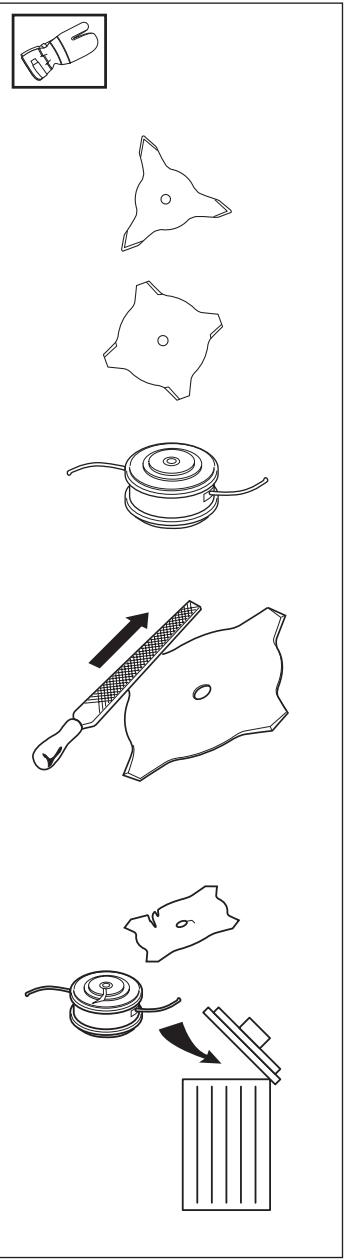
The J-handle set contains the following parts:
1 J-handle
1 Grass blade guard
1 Grass blade
1 Support cup
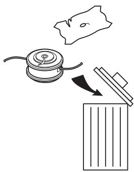
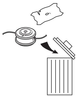
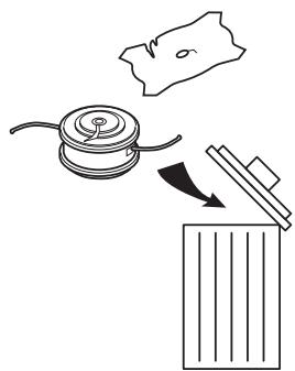
NOTE! The trimmer guard should be replaced with the supplied grass blade guard if the machine is fitted with a grass blade.

WARNING!
Saw blades must not be fitted on a machine equipped with a J-handle.

Read through the Operator's Manual carefully and understand the content before using the machine.
These instructions supplement the instructions that were included with the machine. For other procedures, please refer to the operating instructions for the machine.
List of contents
CONTENTS
Components in the J-handle set .... 1
List of contents ...... 1
SAFETY INSTRUCTIONS
Cutting equipment 2
Basic clearing techniques.... 3
ASSEMBLY
Assembling the J-handle 4
Transport position, J-handle 4
Assembly of the blade and trimmer head.... 4
Assembling the blade guard and grass blade 4
START AND STOP
Control before starting.... 5
TECHNICAL DATA
J-handle set 5
Cutting equipment
This section describes how through correct maintenance and through using the right type of cutting equipment you can:
- Reduce the machine's tendency to kickback
- Obtain maximum cutting capacity.
- Increase the service life of the cutting equipment.
The three basic rules:
1) Only use the cutting and guard equipment we recommend! See chapter "Technical data".
2) Keep the blade's teeth well and correctly sharpened! Follow our instructions and use the recommended filing gauge. An incorrectly sharpened or damaged blade increases the risk of an accident.
3) Check the cutting equipment with regard to damage and crack formation. Damaged cutting equipment should always be replaced.
IMPORTANT INFORMATION
The section describes how through correct maintenance and through using the right type of cutting equipment you can reduce the machine's tendency to kickback, obtain maximum clearing capacity and increase the service life of the cutting equipment.
- Only use the cutting and guard equipment we recommend! See chapter "Technical data".
- Refer to the instructions for the cutting equipment for the correct winding of cord and for the selection of the right cord diameter.
- Keep the blade's teeth well and correctly sharpened! Follow our recommendations. Also refer to the instructions on the blade packaging.

WARNING!
Incorrect cutting equipment or an incorrectly sharpened blade increases the risk of kickback.
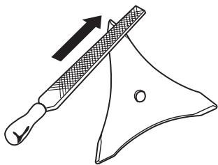
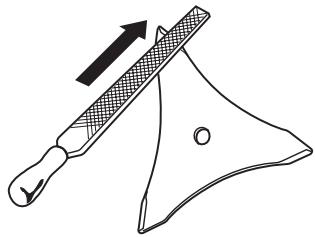
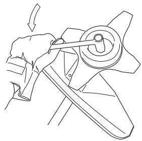
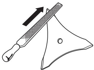
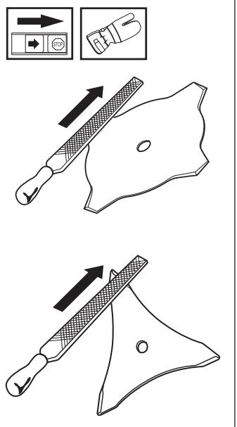
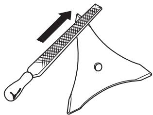
Filing the grass blade
- See the cutting equipment's packaging for correct filing instructions.
- The blades are sharpened using a single cut flat file.
- Sharpen all edges equally to maintain the balance of the blade.
Basic clearing techniques
• Always carry out clearing and trimming at full throttle.
- Always drop to idling speed after each working operation. Longer periods running at full throttle without loading the engine (that is without resistance, which the engine feels from the cutting equipment when trimming) can lead to serious engine damage.
Designations
- Brush cutting is a general term for clearing grass. Grass blades are used for this purpose.
- Grass trimming is a general term for light clearing, e.g. around edges or around trees. A trimmer head or plastic blade is used.


WARNING!
Sometimes grass can collect in the spray guard and cutting head. Always stop the engine when cleaning.
Brush cutting using a grass blade
- A blade is used for all types of high or thick grass.
- The grass is cut down with a sideways, swinging movement, where the movement from right-to-left is the clearing stroke and the movement from left-to-right is the return stroke. Let the blade work on the left-hand side (between 8 and 12 o'clock).
- If the blade is angled to the left when clearing the grass will collect in a line, which makes collection easier, e.g. when raking.
- Try to work rhythmically. Stand firmly with your feet apart. Move forward after the return stroke and stand firmly again.
- Let the support cup rest lightly against the ground. It is used to protect the blade from hitting the ground.
- Reduce the risk of material wrapping around the blade by following these instructions:
a) Always work at full throttle.
b) Avoid the previously cut material during the return stroke.
- Stop the engine, loosen the harness and place the machine on the ground before you start to collect the cut material.

WARNING!
Neither the user of the tool or anyone else may attempt to remove the cut material while the engine is running or with the blade rotating as this can result in serious injury.
Stop the engine and blade before you remove material that has wound around the blade as otherwise there is a risk of injury.

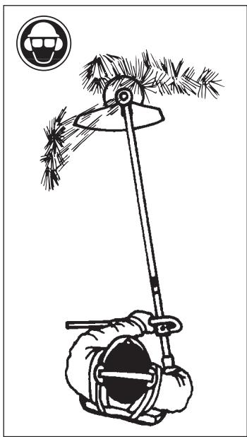
WARNING!
Warning for thrown objects. Always wear protective glasses. Never lean over the guard. Stones, rubbish, etc. can be thrown up into the eyes causing blindness or serious injury.
Keep unauthorised persons at a distance. Children, animals, onlookers and helpers should be kept outside the safety zone of 15 m. Stop the machine immediately if anyone approaches.
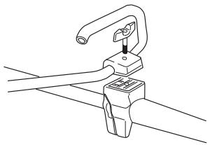
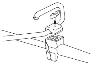
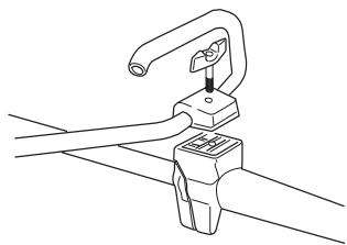
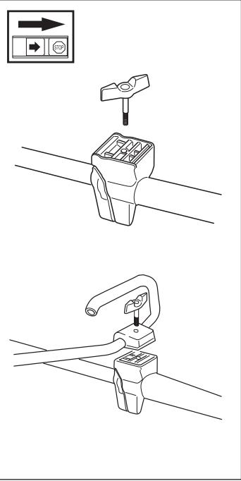
Assembling the J-handle

WARNING
Only grass blades or trimmer heads/plastic blades may be used when the J-handle is fitted. Clearing blades must never be used with the J-handle.
- Loosen the knob from the handle bracket.
- Position the handle as shown. Fit the bracket components and tighten the handle lightly.
- Finely adjust the J-handle to give a comfortable working stance. Tighten the knob.
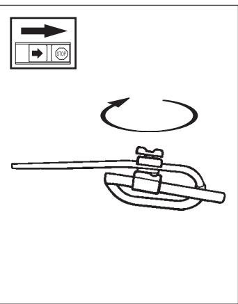
Transport position, J-handle
- The handlebars can easily be turned to fit along the shaft for easy transportation and storage.
- Loosen the knob. Turn the J-handle clockwise.
- Thereafter fold the handlebars around the shaft. Tighten the handle.
- Attach the transport guard.
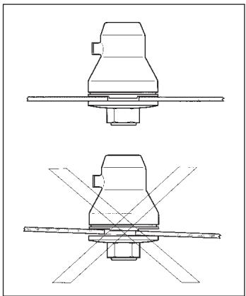
Assembly of the blade and trimmer head
It is extremely important that the disc drive's/support flange's guide engages correctly in the cutting equipment's centre hole when assembling the cutting equipment. Cutting equipment assembled incorrectly can result in serious and/or fatal personal injury.

WARNING!
Do not attach any blade to the unit without proper installation of all required parts. Failure to use the proper parts can cause the blade to fly off and seriously injure the operator and/or bystanders.
Under no circumstances may the cutting equipment be used without an approved guard fitted. See the chapter “Technical data”. If the wrong guard or a defective guard is fitted this can cause serious personal injury.
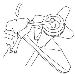
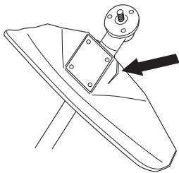
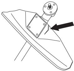
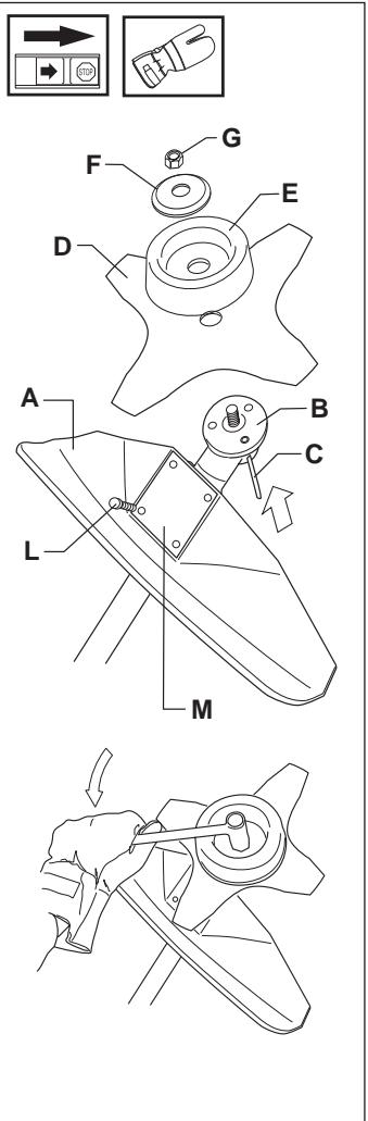
Assembling the blade guard and grass blade
- The guard (A) is fitted using 4 screws (L) and the support plate (M) as set out in the diagram. NOTE! Use the recommended blade guard.
- Fit the drive disc (B) on the output axle.
- Turn the blade axle until one of the holes in the drive disc aligns with the hole in the gear housing.
- Insert the locking pin (C) in the hole so that the axle is locked.
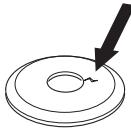
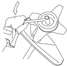
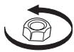
- Place the blade (D), support cup (E) and support flange (F) on the output axle.
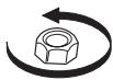
- Fit the nut (G). The tightening torque of the nut is 35-50 Nm (3,5 - 5 kpm). Use the socket spanner in the tool kit. Hold the handle of the spanner as close to the blade guard as possible. The nut is tightened when the spanner is turned against the direction of rotation (left-hand thread).
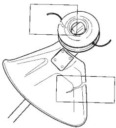
Control before starting
For reasons of safety follow these recommendations!
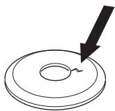
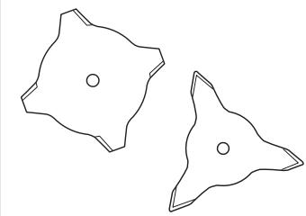
- Check the blade to ensure that no cracks have formed at the bottom of the teeth or by the centre hole. The most common reason why cracks are formed is that sharp corners have been formed at the bottom of the teeth while sharpening or that the blade has been used with dull teeth. Discard a blade if cracks are found.
- Check that the support flange is not cracked due to fatigue or due to being tightened too much. Discard the support flange if it is cracked.
- Ensure the locking nut has not lost its captive force. The nut lock should have a locking force of at least 1.5 Nm. The tightening torque of the locking nut should be 35-50 Nm.
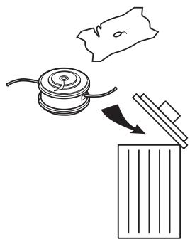
- Check that the guard is not damaged or cracked. Replace the guard if it is exposed to impact or is cracked.
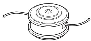
- Check that the trimmer head and spray guard are not damaged or cracked. Replace the trimmer head or spray guard if they are exposed to impact or are cracked.
- Never use the machine without a guard or spray guard nor with a defective guard.
![graph TD A["Eye Contact"] --> B["Close Top"] B --> C["Close Bottom"] C --> D["Rotate Ring with nut"] D --> E["Rotate Ring with nut"] E --> F["Final Assembly with Close Top and Close Bottom"]](/content/2020/05/80649/images/e9e60dbeff8a9dd8ee9bae8766f731c9d65a9b9168e6dca42b9bc3cea986e62b.jpg)
TECHNICAL DATA
| Approved accessories J-handle | Type | Cutting attachment guard Art No. |
| Centre hole in blades ∅ 20 mm | ||
| Threaded blade axle M10 | ||
| Grass blade | Grass 255-4 (∅ 255 4-teeth) | 503 74 40-01 |
| Grass 255-8 (∅ 255 8-teeth) Not 240L | 503 74 40-01 | |
| Multi 255-3 (∅ 255 3-teeth) | 503 74 40-01 | |
| Plastic knives | Tricut ∅ 300 | 503 74 50-04 |
| Trimmer head | Trimmy Fix | 503 74 50-04 |
| Trimmy Hit Pro | 503 74 50-04 | |
| Superauto II | 503 74 50-04 | |
| Trimmy HII | 503 74 50-04 | |
| Support cup | Fixed | - |

ΠΡΟΣΟΧΗ!

ΠΡΟΣΟΧΗ!
TEXNIKA ΣΤΟΙΧΕΙΑ
- VIKTIG INFORMATION
- WARNING
- KONTROLL FÖRE START
- VIKTIG INFORMASJON
- TRANSPORTSTILLING, J-HÅNDTAK
- KONTROLL FØR START
- VIGTIG INFORMATION
- ADVARSEL
- TRANSPORTSTILLING, J-HÅNDTAG
- MONTERING AF KLINGE OG TRIMMERHOVED
- KONTROL FØR START
- TÄRKEÄ TIETÄÄ
- VAROITUS
- KULJETUSASENTO, J-KAHVA
- WARNUNG
- ATENÇÃO
- ATENCIÓN
- WAARSCHUWING
- TRANSPORTPOSITIE, J-HANDVAT
- INFORMATIONS IMPORTANTES
- AVERTISSEMENT
- ATTENZIONE
- THE J-HANDLE SET CONTAINS THE FOLLOWING PARTS
- LIST OF CONTENTS
- CONTENTS
- SAFETY INSTRUCTIONS
- ASSEMBLY
- START AND STOP
- TECHNICAL DATA
- CUTTING EQUIPMENT
- IMPORTANT INFORMATION
- FILING THE GRASS BLADE
- BASIC CLEARING TECHNIQUES
- DESIGNATIONS
- BRUSH CUTTING USING A GRASS BLADE
- ASSEMBLING THE J-HANDLE
- TRANSPORT POSITION, J-HANDLE
- ASSEMBLY OF THE BLADE AND TRIMMER HEAD
- ASSEMBLING THE BLADE GUARD AND GRASS BLADE
- CONTROL BEFORE STARTING
- ΠΡΟΣΟΧΗ
Brand : HUSQVARNA
Model : J-HANDLE
Category : Garden tools