
Wonderwall Air Ait Infinity - Heating Klarstein - Free user manual and instructions
Find the device manual for free Wonderwall Air Ait Infinity Klarstein in PDF.

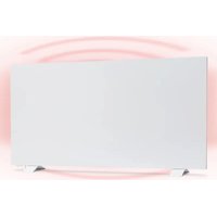
| Product Type | Wall-mounted infrared heater |
| Brand | Klarstein |
| Model | Wonderwall Air Ait Infinity |
| Nominal heating power | 300 W, 580 W or 720 W depending on model |
| Power supply | 220-240 V ~ 50 Hz |
| Dimensions (W x H x D) | Model 300 W: 505 x 595 x 16 mm Model 580 W: 595 x 900 x 16 mm Model 720 W: 595 x 1195 x 16 mm |
| Weight | Approximately 4.5 kg (estimate) |
| Heating type | Infrared, fanless |
| Temperature control | Electronic control with thermostat, weekly timer |
| Special functions | Open window detection, weekly programming, manual mode |
| Remote control | Yes, with range of 10 meters |
| Installation | Wall-mounted, minimum distance from floor 20 cm, clearances: 30 cm front/top/back, 10 cm sides |
| Maintenance and cleaning | Unplug and let cool, clean with a soft dry cloth, no abrasive products |
| Safety | Do not cover, do not use with an external timer, automatic shutdown in case of open window detection |
| Remote control batteries | 2 AA batteries (not included) |
| Recycling | Do not dispose of with household waste, take to a WEEE collection point |
Frequently Asked Questions - Wonderwall Air Ait Infinity Klarstein
User questions about Wonderwall Air Ait Infinity Klarstein
0 question about this device. Answer the ones you know or ask your own.
Ask a new question about this device
Download the instructions for your Heating in PDF format for free! Find your manual Wonderwall Air Ait Infinity - Klarstein and take your electronic device back in hand. On this page are published all the documents necessary for the use of your device. Wonderwall Air Ait Infinity by Klarstein.
USER MANUAL Wonderwall Air Ait Infinity Klarstein
Note: The device is not suitable for use as a primary heat source.
INHALT
Technische Daten 3
Produktdatenblatt 4
natural_image
Symbol of a trash bin with crossed x and y axes, no text or labels presentCongratulations on purchasing this equipment. Please read this manual carefully and take care of the following hints to avoid damages. Any failure caused by ignoring the mentioned items and cautions mentioned in the instruction manual are not covered by our warranty and any liability. Scan the QR code to get access to the latest user manual and other information about the product.

CONTENTS
Technical Data 21
Product Data Sheet 22
Safety Instructions 25
Wall Installation 26
Remote Control Display Indicators 27
Operation and Functions 27
Quick Start 29
Disposal Considerations 35
Manufacturer & Importer (UK) 35
TECHNICAL DATA
| Item numer Power Power supply Dimensions | |||
| 1003516810035171 | 300 W (±10%) | 220-240 Vx900x16 mm~ 50 Hz | 505x595x16 mm |
| 1003516910035172 | 580 W (±10%) 595 | ||
| 1003517010035173 | 720 W (±10%) 595 | x1195x16 mm | |
PRODUCT DATA SHEET
| Model identifier(s): 10035168, 10035171 | ||||||
| Item Sym- | bol | Value Unit Item Unit | ||||
| Heat output Type of heat input, for electric storage local space heaters only | ||||||
| Nominal heat output P | nom | 0.3 kW | manual | heat charge control, with integrated thermostat | no | |
| Minimum heat output (indicative) | P_min | 0.0 kW | manual | heat charge control with room and/or outdoor temperature feedback | no | |
| Maximum continuous heat output | P_max,c | 0.3 kW | electronic | heat charge control with room and/or outdoor temperature feedback | no | |
| Auxiliary electricity consumption fan assisted heat output no | ||||||
| At nominal heat output (fan motor) | el_max | 0.300 kW | Type of heat output/room temperature control | |||
| At minimum heat output (fan motor) | el_min | 0.000 kW | single stage heat output and no room temperature control | no | ||
| In standby mode el | SB | 0.000 W | Two or more manual stages, no room temperature control | no | ||
| with mechanic thermostat room temperature control | no | |||||
| with electronic room temperature control | no | |||||
| electronic room temperature control plus day timer | no | |||||
| electronic room temperature control plus week timer | yes | |||||
| Other control options (multiple selections possible) | ||||||
| room temperature control, with presence detection | no | |||||
| room temperature control, with open window detection | yes | |||||
| with distance control option no | ||||||
| with adaptive start control | no | |||||
| with working time limitation | no | |||||
| with black bulb sensor | no | |||||
| Contact details | Chal-Tec GmbH, Wallstraße 16, 10179, Berlin, Germany | |||||
| Model identifier(s): 10035169, 10035172 | ||||||
| Item Sym- | bol | Value Unit Item Unit | ||||
| Heat output Type of heat input, for electric storage local space heaters only | ||||||
| Nominal heat output P | nom | 0,58 kW | manual | heat charge control, with integrated thermostat | no | |
| Minimum heat output (indicative) | P_min | 0,0 kW | manual | heat charge control with room and/or outdoor temperature feedback | no | |
| Maximum continuous heat output | P_max,c | 0,58 kW | electronic | heat charge control with room and/or outdoor temperature feedback | no | |
| Auxiliary electricity consumption fan assisted heat output no | ||||||
| At nominal heat output (fan motor) | el_max | 0.580 kW | Type of heat output/room temperature control | |||
| At minimum heat output (fan motor) | el_min | 0.000 kW | single stage heat output and no room temperature control | no | ||
| In standby mode el | SB | 0.000 W | Two or more manual stages, no room temperature control | no | ||
| with mechanic thermostat room temperature control | no | |||||
| with electronic room temperature control | no | |||||
| electronic room temperature control plus day timer | no | |||||
| electronic room temperature control plus week timer | yes | |||||
| Other control options (multiple selections possible) | ||||||
| room temperature control, with presence detection | no | |||||
| room temperature control, with open window detection | yes | |||||
| with distance control option no | ||||||
| with adaptive start control | no | |||||
| with working time limitation | no | |||||
| with black bulb sensor | no | |||||
| Contact details | Chal-Tec GmbH, Wallstraße 16, 10179, Berlin, Germany | |||||
| Model identifier(s): 10035170, 10035173 | ||||||
| Item Sym- | bol | Value Unit Item Unit | ||||
| Heat output Type of heat input, for electric storage local space heaters only | ||||||
| Nominal heat output P | nom | 0.72 kW | manual | heat charge control, with integrated thermostat | no | |
| Minimum heat output (indicative) | Pmin | 0.0 kW | manual | heat charge control with room and/or outdoor temperature feedback | no | |
| Maximum continuous heat output | Pmax,c | 0.72 kW | electronic | heat charge control with room and/or outdoor temperature feedback | no | |
| Auxiliary electricity consumption fan assisted heat output no | ||||||
| At nominal heat output (fan motor) | elmax | 0.720 kW | Type of heat output/room temperature control | |||
| At minimum heat output (fan motor) | elmin | 0.000 kW | single stage heat output and no room temperature control | no | ||
| In standby mode el | SB | 0.000 W | Two or more manual stages, no room temperature control | no | ||
| with mechanic thermostat room temperature control | no | |||||
| with electronic room temperature control | no | |||||
| electronic room temperature control plus day timer | no | |||||
| electronic room temperature control plus week timer | yes | |||||
| Other control options (multiple selections possible) | ||||||
| room temperature control, with presence detection | no | |||||
| room temperature control, with open window detection | yes | |||||
| with distance control option no | ||||||
| with adaptive start control | no | |||||
| with working time limitation | no | |||||
| with black bulb sensor | no | |||||
| Contact details | Chal-Tec GmbH, Wallstraße 16, 10179, Berlin, Germany | |||||
SAFETY INSTRUCTIONS
- Do not use the appliance until it is securely fixed as described in this manual.
- Check that the voltage indicates on the data plate corresponds with that of the local network before connecting the appliance to the mains power supply.
- If the supply cord is damaged, it must be replaced by a qualified engineer in order to avoid a hazard.
- The fireplace heater must not be positioned directly under the power socket.
- Keep furniture, curtains and other flammable material at least 1 meter away from the appliance.
- Do not leave the appliance unattended during use.
- Do not leave the appliance unattended whilst connected to the mains supply.
- Keep out of reach of children and do not allow them to operate this appliance.
- This appliance is intended for household use only and should not be used for industrial purposes.
- Do not operate this appliance after a malfunction or after being damaged in any way.
- Repairs to electrical appliances should only be performed by a qualified electrician.
- Improper repairs may place user at serious risk.
- Do not run the mains cable under carpets, rugs, etc.
- Do not allow the mains cable to hang over sharp edges or come in contact with hot surfaces.
- In order to avoid overheating, do not cover the heater.
- Do not use this heater with a programmer, timer, separate remote control system or any other device that switches the heater on automatically, since a fire risk exists if the heater is covered or positioned incorrectly.
- Never immerse the product in water or any other liquid for any reasons.
- Do not use this heater in the immediate surroundings of a bath, a shower or a swimming pool.
- Do not use the appliance outdoors.
- Do not use if you have wet hands.
- Never use the appliance on or near hot surfaces.
- Do not operate with a damaged cord.
- Before cleaning the appliance, make sure it is unplugged from the power and that it is completely cooled.
- Do not clean the appliance with abrasive chemicals.
- Never use accessories that are not recommended or supplied by the manufacturer. It could cause danger to the user or damage to the appliance.
- This appliance is not intended for use by persons (including children) with reduced Physical, sensory or mental capabilities, or lack of experience and knowledge unless they have been given supervision or instruction concerning use of the appliance by a person responsible for their safety.
- Children should be supervised to ensure that they do not play with the appliance.
CAUTION
Risk of burns! Some parts of this product can become very hot and cause burns. Particular attention has to be given where children and vulnerable people are present.
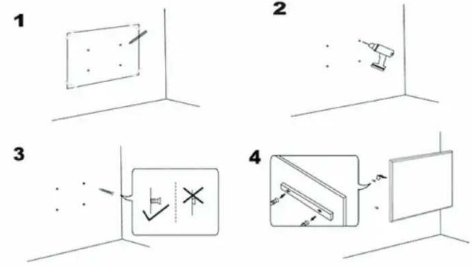
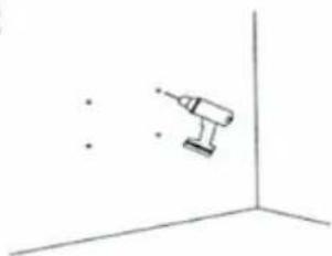
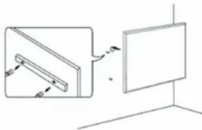
WALL INSTALLATION
Important installation instructions
- Continuous operation shortens the service life of the heaters. If possible, the appliance should be paused every 12 hours.
- Do not use the unit when the ambient temperature is above 20 °C, as high temperatures will affect performance.
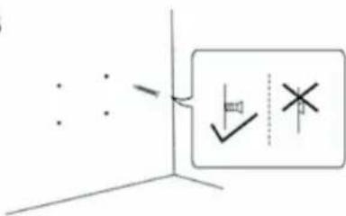
• The outlet should be at least 20 cm above the ground. - Keep the unit away from flammable and explosive materials.
- Leave a safety distance of 30 cm around the unit to the front, top and rear. Leave a safety distance of 10 cm to the right and left around the unit.
- During the first one or two days, new heaters may emit odours that are harmless to humans.
2
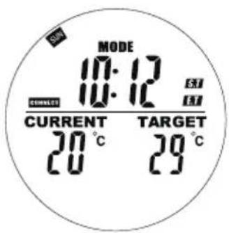
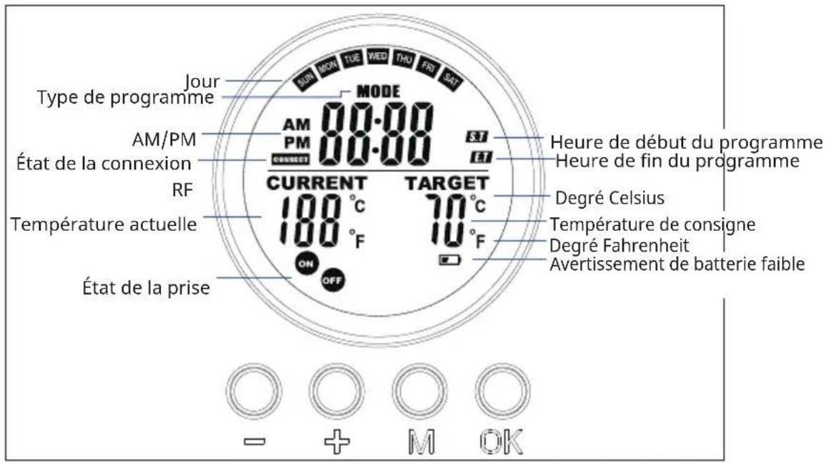
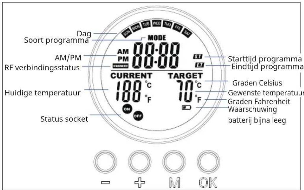
REMOTE CONTROL DISPLAY INDICATORS
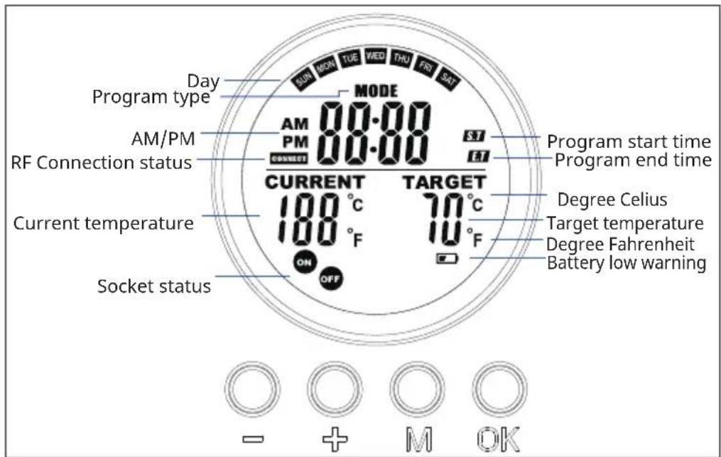
OPERATION AND FUNCTIONS
Button [M]
- Press the [M] button switch between System time/Thermostat
- Press and hold the [M] button under certain program slot to initiate a programming into the slot.
Button [OK]
- Press[OK].
- Choose the 1,2,3,4 slot. Press [OK] to turn on/off the slot.
- Under programming or setting status, press the OK button to confirm and proceed to next step.
Button [+] and [-]
- Choose the program slots.
- Press button increase or decrease, the digit in programming and setting mode, press and hold [-] or [+] to fast increase/decrease.
Pair to control box
- Press and hold [+] and [-] simultaneously to start pairing. The CONNECT icon will blink on the display to indicate that the remote is attempting to connect to the unit.
- Turn on the heater at the side switch. The unit will now be in pairing mode for 60 seconds.
- Wait until the CONNECT symbol stops flashing and lights up permanently in the display. The remote control is now connected to the heater.
Note: The remote control only works within a radius of 10 meters from the unit. Establishing the connection usually takes 5 seconds.
Pair to control box
| 1. Turn on the heating panel using the switch on the back. | 2. Point to the heating panel and press and hold "+" and "-" simultaneously. Two beeps indicate successful pairing. |
Note: The remote control only works within a radius of 10 meters from the unit. Establishing the connection usually takes 5 seconds.
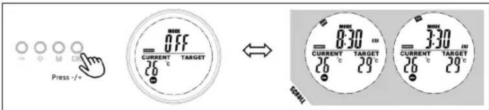
QUICK START
Manual Override
Press the [OK] button repeatedly to select one of the following functions:
- Manual temperatur setting
- OFF
• ON
Note: Manual operation override all slot programs, and set all running slots into OFF status. Vice verse, turning on slots program will erase all manual setting.
Manual operation will features in the switch ON/OFF icons stay on while slot program will feature in the ON/OFF icons flashing.
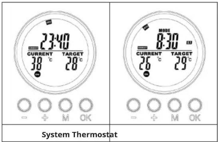
| MODE 3.53 3.53 CURRENT TARGET 26 °C 20°C 20 ON - + M OK | 23:40 CURRENT 30 °C ON - + M OK | 8:30 CURRENT TARGET 26 °C 29°C ON - + M OK |
| Manual switch-off of the system (the symbol lights up continuously) | Switching on the system manually (the symbol lights up continuously) | Manual setting of the temperature (the symbol lights up continuously) |
Program on-the-run
Activate either of the slots program will erase the manual setting, and execute the slot program instead.
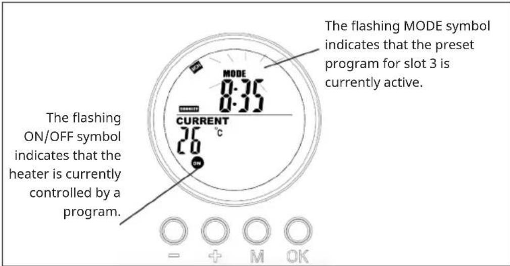
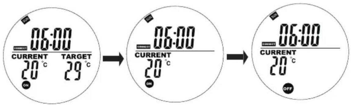
Display on System page when program is on-the-run
flowchart
graph TD
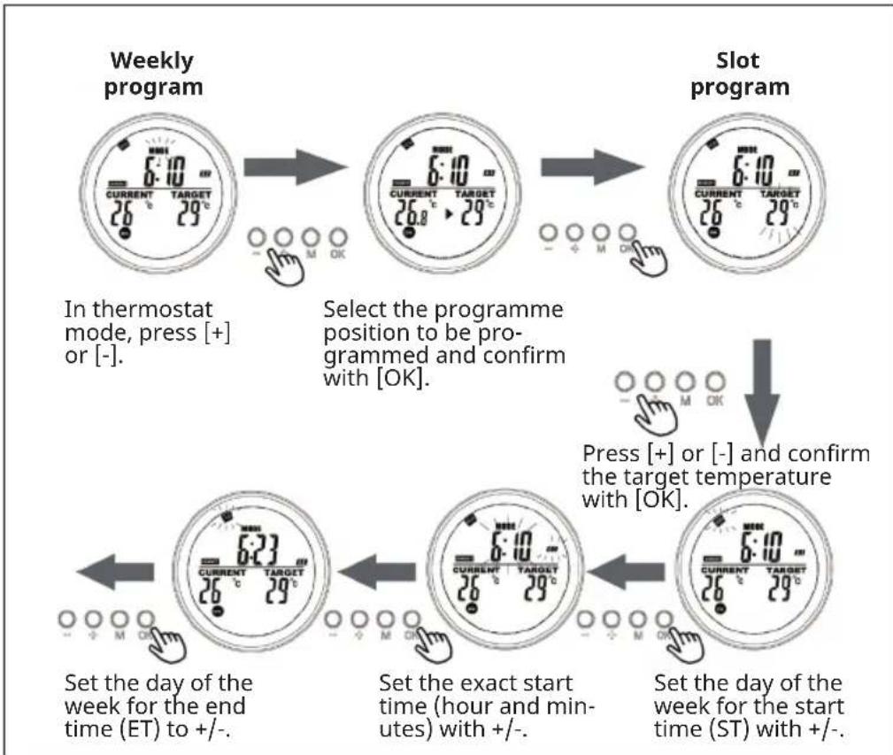
A["Weekly program"] --> B["Select the programme position to be programmed and confirm with [OK"]]
B --> C["Press [+"] or["-"] and_confirm_the_target_temperature_with["OK"]]
C --> D["Set the day of the week for the end time (ET) to +/-"]
D --> E["Set the exact start time (hour and minutes) with +/-"]
E --> F["Set the day of the week for the start time (ST) with +/-"]
![SET the exact end time (hour and minutes) with +/- and confirm with [OK]. Programming is now complete.](/content/2026/05/757563/images/c3768a57db31cb49142f85c6d376a3b03103154a2f39d1fb0e78584b58e6aa63.jpg)
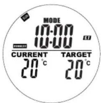
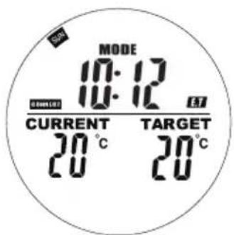
Current day of week and time settings
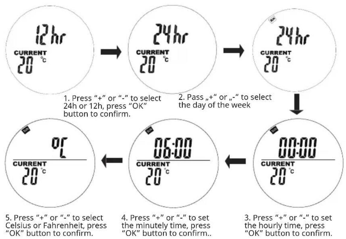
Press and hold „M“ to enter the interface of setting the current time and day of the week. Press „+“ and „-“ to select. Press „OK“ to confirm.
flowchart
graph TD
    A["12hr CURRENT 20°C"] --> B["24hr CURRENT 20°C"]
    B --> C["24hr CURRENT 20°C"]
    C --> D["06:00 CURRENT 20°C"]
    D --> E["00:00 CURRENT 20°C"]

    style A fill:#f9f,stroke:#333
    style B fill:#f9f,stroke:#333
    style C fill:#f9f,stroke:#333
    style D fill:#f9f,stroke:#333
    style E fill:#f9f,stroke:#333

    note1["1. Press "+" or "-" to select 24h or 12h, press "OK" button to confirm."] --> note1
    note2["2. Pass "+" or "-" to select the day of the week"] --> note2
    note3["3. Press "+" or "-" to set the hourly time, press "OK" button to confirm."] --> note3
    note4["4. Press "+" or "-" to set the minutely time, press "OK" button to confirm."] --> note4
    note5["5. Press "+" or "-" to select Celsius or Fahrenheit, press "OK" button to confirm."] --> note5
In Automatic Mode, press the „+” or „-” buttons to adjust the target temperature to your desired setting.
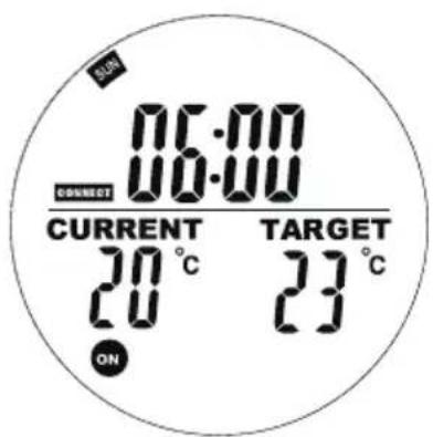
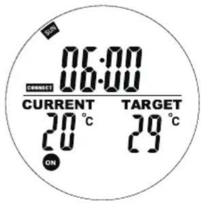
Weekly programming setting
Short press the „M“ button to enter the interface of setting weekly programming.
"00" on the left flashes and "ST" is displayed. Press + or - to set the start heating time. Press the OK button to confirm.
"00" on the right flashes and "ET" is displayed.
Press + or - to set the end heating time. Press the OK button to confirm.
Press the + or - buttons to set your target temperature. Press the M button to the next day setting.
Notes about programs
- Place the remote control and the heating panel in the same room.
- If a battery icon stays on the remote's screen, it means the battery is running low. A low battery may cause the remote to malfunction or stop working. Please replace the battery promptly to avoid interruptions.
- Make sure the straight-line distance between them is no more than 5 meters for proper communication.
- Red light ON: The system is powered and the main board is working normally. Green light ON: The heating panel is currently heating.
Weekly programming settings
- Before setting a schedule, please ensure to set the correct day and time first. Without this, weekly programming will not function correctly.
- Choose the hour to turn ON and the hour to turn OFF each day. Example: Turn ON at 10:00 AM, turn OFF at 5:00 PM.
- Weekly programming will not activate if the turn ON time is the same as or later than the turn OFF time. For example, if you set the heater to turn ON at 10:00 and OFF at 8:00, the system will ignore the schedule for that day. To skip heating on a specific day, simply set the turn ON time to be the same as or later than the turn OFF time.
- The system uses a 24-hour format by default. If you enter a 12-hour time format, the system will automatically convert it—no need to adjust manually.
- The heater runs only when both time and temperature settings are met.
Example
• ON time: 10:00 AM
• OFF time: 12:00 PM
- Set temperature: 25^ C
- Heating will start if the temperature drops to 22^ or lower (current ambient temperature 3 degree lower than the set temperature).
- Heating will stop if the temperature rises to above 25^ (current ambient temperature 1 degree higher than the set temperature).
- Outside the scheduled time, the heater will not turn on, even if the temperature is low.
If you choose a specific day in a week as ST, then you can choose any day as ET. the switch will be turned ON/OFF base on the specific ST day and time to ET. day and time in a range of one week, and the program will repeat every week.
Display slot info
Users can view their programmed time or temperature by selecting the slot in program mode, user are allow to close or open the slot easily.
- Go the programme mode.
- Select the target slot you want to view, the programmed start time and end time will scroll in 1 second and repeat, all other information is displayed as well.
- Press the OK button to turn off this slot, press again to recover the slot.
Open-window mode
Note: Open-window mode when running overrides all modes.
- If the temperature in the room drops by more than 6 °C within 20 minutes, the device interprets this as an open window and the heating switches off automatically.
- As long as the mode is active, OPEN flashes in the display.
- Press any button on the remote control to return to the manual setting mode.
Battery change
- Remove the cover of the battery compartment.
- Replace the old batteries with 2 new AA batteries and close the battery compartment again.
DISPOSAL CONSIDERATIONS
natural_image
Symbol of a trash bin with crossed lines indicating no waste, and a solid black rectangle below (no text or labels)If there is a legal regulation for the disposal of electrical and electronic devices in your country, this symbol on the product or on the packaging indicates that this product must not be disposed of with household waste. Instead, it must be taken to a collection point for the recycling of electrical and electronic equipment. By disposing of it in accordance with the rules, you are protecting the environment and the health of your fellow human beings from negative consequences. For information about the recycling and disposal of this product, please contact your local authority or your household waste disposal service.
This product contains batteries. If there is a legal regulation for the disposal of batteries in your country, the batteries must not be disposed of with household waste. Find out about local regulations for disposing of batteries. By disposing of them in accordance with the rules, you are protecting the environment and the health of your fellow human beings from negative consequences.
MANUFACTURER & IMPORTER (UK)
Chal-Tec GmbH, Mühlenstrasse 25, 10243 Berlin, Germany.
Contact: info@electronic-star.de
Chère cliente, cher client,
SOMMAIRE
Fiche technique 37
Installation murale 42
natural_image
Simple 3D diagram showing a rectangular box with four dots inside and an arrow pointing to it, placed on a vertical axis (no text or symbols)2
natural_image
Simple line drawing of a screwdriver positioned at a corner with three dots (no text or symbols)3
4
natural_image
Diagram showing a 3D object with an inset view of a rectangular panel and its projection onto a wall (no text or symbols present)VOYANTS DE LA TÉLÉCOMMANDE
natural_image
Symbol of a trash bin with crossed lines indicating no waste, and a solid black rectangle below (no text or labels)INDICE
Dati tecnici 53
natural_image
Symbol of a trash bin with crossed lines and a blank rectangular base (no text or labels)ÍNDICE
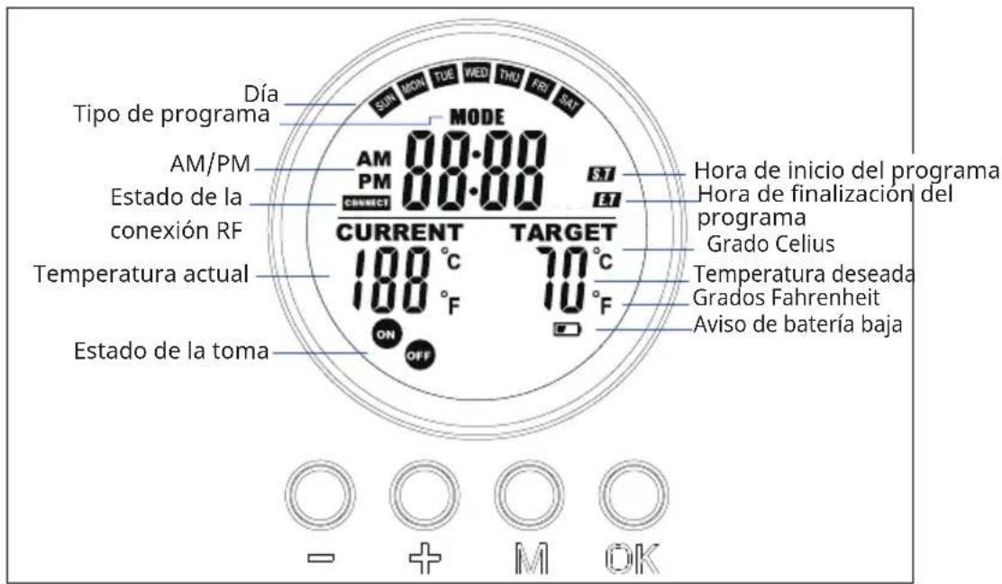
INDICADORES DE LA PANTALLA DEL MANDO A DISTANCIA
natural_image
Symbol of a trash bin with crossed lines indicating no waste, and a solid black rectangle below (no text or labels)INHOUD
WEERGAVE DISPLAY AFSTANDBEDIENING
natural_image
Symbol of a trash bin with crossed lines indicating no waste, and a solid black rectangle below (no text or labels)
- INHALT
- CONTENTS
- TECHNICAL DATA
- SAFETY INSTRUCTIONS
- CAUTION
- WALL INSTALLATION
- Important installation instructions
- REMOTE CONTROL DISPLAY INDICATORS
- OPERATION AND FUNCTIONS
- Button [M]
- Button [OK]
- Button [+] and [-]
- Pair to control box
- QUICK START
- Manual Override
- Program on-the-run
- Current day of week and time settings
- Weekly programming setting
- Notes about programs
- Weekly programming settings
- Example
- Display slot info
- Open-window mode
- Battery change
- DISPOSAL CONSIDERATIONS
- MANUFACTURER & IMPORTER (UK)
- SOMMAIRE
- VOYANTS DE LA TÉLÉCOMMANDE
- INDICE
- ÍNDICE
- INDICADORES DE LA PANTALLA DEL MANDO A DISTANCIA
- INHOUD
- WEERGAVE DISPLAY AFSTANDBEDIENING
Brand : Klarstein
Model : Wonderwall Air Ait Infinity
Category : Heating